Table of Contents
Advertisement
Quick Links
Advertisement
Table of Contents

Related Manuals for LMI Technologies 2320


Summary of Contents for LMI Technologies 2320
- Page 1 Gocator 2300 & 2880 Series USER MANUAL Document revision: C...
-
Page 2: Copyright
LMI Technologies, Inc. Trademarks and Restrictions Gocator™ is a registered trademark of LMI Technologies, Inc. Any other company or product names mentioned herein may be trademarks of their respective owners. Information contained within this manual is subject to change. -
Page 3: Table Of Contents
Table of Contents Resolution and Accuracy X Resolution Z Resolution Copyright Z Linearity Table of Contents Profile Output Introduction Coordinate Systems Safety and Maintenance Sensor Coordinates Laser Safety System Coordinates Laser Classes Resampled and Uniform Spacing Profile Precautions and Responsibilities Format Class 3B Responsibilities Gocator Web Interface... - Page 4 Scan Modes Measure Page Overview Triggers Data Viewer Trigger Examples Tools Panel Trigger Settings Measurement Tool Management Sensor Adding and Removing Tools Active Area Enabling and Disabling Measurements 113 Tracking Window Editing a Tool or Measurement Name Transformations Changing a Measurement ID Exposure Common Measurement Settings Single Exposure...
- Page 5 Stud EdgeFiltering Measurement Region Triggers Volume Tools Script Profile Types Script Measurement ProfileRegion2D Built-in Functions ProfileFeature Output ProfileLine Output Page Overview Surface Types Ethernet Output Region3D Digital Output SurfaceRegion2D Analog Output SurfaceFeature Serial Output ProfileArea Dashboard ProfileCircle Dashboard Page Overview ProfileDimension System Panel ProfileGroove Measurements...
- Page 6 Transform Schedule Digital Output Device Schedule Analog Output Protocols Ping Gocator Protocol Reset General Backup Modes Restore Buddy Communication Channels Restore Factory States Set Recording Enabled Data Types Get Recording Enabled Status Codes Clear Replay Data Discovery Commands Set Playback Source Get Address Get Playback Source Set Address...
-
Page 7: Gocator 2300 & 2880 Series
Moving Alignment CSV Converter Tool Clear Alignment Troubleshooting Data Commands Specifications Get Result Gocator 2300 Series Get Value Gocator 2320 Get Decision Gocator 2330 Health Commands Gocator 2340 Get Health Gocator 2350 Software Development Kit Gocator 2370 Setup and Locations... - Page 8 Gocator 2880 Sensor Gocator 2880 Gocator Power/LAN Connector Grounding Shield Power Laser Safety Input Gocator 2300 & 2880 I/O Connector Grounding Shield Digital Outputs Inverting Outputs Digital Inputs Encoder Input Serial Output Analog Output Master 100 Master 100 Dimensions Master 400/800 Master 400/800 Electrical Specifications Master 400/800 Dimensions Master 1200/2400...
-
Page 9: Introduction
Introduction The Gocator 2300 series of laser profiling sensors is designed for 3D measurement and control applications. Gocator sensors are configured using a web browser and can be connected to a variety of input and output devices. This documentation describes how to connect, configure, and use a Gocator. It also contains reference information on the device's protocols and job files. -
Page 10: Safety And Maintenance
Safety and Maintenance The following sections describe the safe use and maintenance of Gocator sensors. Laser Safety Gocator sensors contain semiconductor lasers that emit visible or invisible light and are designated as Class 2M, Class 3R, or Class 3B, depending on the chosen laser option. Gocator sensors are referred to as components, indicating that they are sold only to qualified customers for... -
Page 11: Laser Classes
Laser Classes Class 2M laser components Class 2M laser components would not cause permanent damage to the eye under reasonably foreseeable conditions of operation, provided that any exposure can be terminated by the blink reflex (assumed to take 0.25 seconds). Because classification assumes the blink reflex, the wavelength of light must be in the visible range (400 nm to 700 nm). -
Page 12: Precautions And Responsibilities
Class 3B Responsibilities LMI Technologies has filed reports with the FDA to assist customers in achieving certification of laser products. These reports can be referenced by an accession number, provided upon request. Detailed descriptions of the safety items that must be added to the system design are listed below. -
Page 13: Nominal Ocular Hazard Distance (Nohd)
Beam Attenuators A permanently attached method of preventing human access to laser radiation other than switches, power connectors or key control must be employed. On some LMI laser sensors, the beam attenuator is supplied with the sensor as an integrated mechanical shutter. Emission Indicator It is required that the controls that operate the sensors incorporate a visible or audible indicator when power is applied and the lasers are operating. -
Page 14: Systems Sold Or Used In The Usa
2x80 2645 Systems Sold or Used in the USA Systems that incorporate laser components or laser products manufactured by LMI Technologies require certification by the FDA. Customers are responsible for achieving and maintaining this certification. Customers are advised to obtain the information booklet Regulations for the Administration and Enforcement of the Radiation Control for Health and Safety Act of 1968: HHS Publication FDA 88-8035. -
Page 15: Environment And Lighting
Minimize voltage potential between system ground and sensor ground Care should be taken to minimize the voltage potential between system ground (ground reference for I/O signals) and sensor ground. This voltage potential can be determined by measuring the voltage between Analog_out- and system ground. The maximum permissible voltage potential is 12 V but should be kept below 10 V to avoid damage to the serial and encoder connections. -
Page 16: Sensor Maintenance
Turn off lasers when not in use LMI Technologies uses semiconductor lasers in 3D measurement sensors. To maximize the lifespan of the sensor, turn off the laser when not in use. Avoid excessive modifications to files stored on the sensor Settings for Gocator sensors are stored in flash memory inside the sensor. -
Page 17: Getting Started
Getting Started The following sections provide system and hardware overviews, in addition to installation and setup procedures. System Overview Gocator sensors can be installed and used in a variety of scenarios. Sensors can be connected as standalone devices, dual-sensor systems, or multi-sensor systems. Standalone System Standalone systems are typically used when only a single Gocator sensor is required. -
Page 18: Multi-Sensor System
A Master 400/800/1200/2400 must be used to connect two sensors in a dual-sensor system. Gocator Power and Ethernet to Master cordsets are used to connect sensors to the Master. Multi-Sensor System Master 400/800/1200/2400 networking hardware can be used to connect two or more sensors into a multi-sensor system. - Page 19 Getting Started • System Overview • 19 Gocator 2300 & 2880 Series...
-
Page 20: Hardware Overview
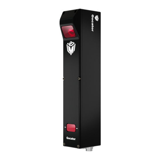
Hardware Overview The following sections describe Gocator and its associated hardware. Gocator 2300 & 2880 Sensor Gocator 2330 Item Description Camera Observes laser light reflected from target surfaces. Laser Emitter Emits structured light for laser profiling. I/O Connector Accepts input and output signals. Power / LAN Connector Accepts power and laser safety signals and connects to 1000 Mbit/s Ethernet network. -
Page 21: Master 100
The maximum cordset length is 60 m. See Gocator 2300 & 2880 I/O Connector (page 354) and for pinout details. See Parts and Accessories (page 367) for cordset lengths and part numbers. Contact LMI for information on creating cordsets with customized lengths and connector orientations. Master 100 The Master 100 is used by the Gocator 2300 series for standalone system setup. -
Page 22: Master 1200/2400
See Master 100 (page 359) for pinout details. Master 400/800 The Master 400 and the Master 800 allow you to connect more than two sensors. The Master 400 accepts four sensors, and the Master 800 accepts eight sensors. Item Description Sensor Ports Master connection for Gocator sensors (no specific order required). -
Page 23: Calibration Targets
Item Description Sensor Ports Master connection for Gocator sensors (no specific order required). Ground Connection Earth ground connection point. Laser Safety Laser safety connection. Encoder Accepts encoder signal. Input Accepts digital input. See Master 1200/2400 (page 364) for pinout details. Calibration Targets Targets are used for alignment and calibrating encoder systems. - Page 24 For wide, multi-sensor systems, bars are required to match the length of the system by following the guidelines illustrated below. (LMI Technologies does not manufacture or sell bars.) See Aligning Sensors (page 87) for more information on alignment. Getting Started • Hardware Overview • 24...
-
Page 25: Installation
Installation The following sections provide grounding, mounting, and orientation information. Grounding - Gocator Gocators should be grounded to the earth/chassis through their housings and through the grounding shield of the Power I/O cordset. Gocator sensors have been designed to provide adequate grounding through the use of M5 x 0.8 pitch mounting screws. -
Page 26: Grounding - Master 400/800/1200/2400
Install a 360-degree ground clamp. Grounding - Master 400/800/1200/2400 The mounting brackets of all Masters have been designed to provide adequate grounding through the use of star washers. Always check grounding with a multi-meter by ensuring electrical continuity between the mounting frame and RJ45 connectors on the front. The frame or electrical cabinet that the Master is mounted to must be connected to earth ground. -
Page 27: Orientations
The sensor must be heat sunk through the frame it is mounted to. When a sensor is properly heat sunk, the difference between ambient temperature and the temperature reported in the sensor's health channel is less than 15° C. Gocator sensors are high-accuracy devices. The temperature of all of its components must be in equilibrium. - Page 28 Single sensor on robot arm Dual-Sensor System Orientations: Side-by-side for wide-area measurement (Wide) Main must be on the left side (when looking into the connector) of the Buddy (Wide) Getting Started • Installation • 28 Gocator 2300 & 2880 Series...
- Page 29 Above/below for two-sided measurement (Opposite) Main must be on the top with Buddy on the bottom (Opposite) Getting Started • Installation • 29 Gocator 2300 & 2880 Series...
-
Page 30: Network Setup
Network Setup The following sections provide procedures for client PC and Gocator network setup. Client Setup Sensors are shipped with the following default network configuration: Setting Default DHCP Disabled IP Address 192.168.1.10 Subnet Mask 255.255.255.0 Gateway 0.0.0.0 All Gocator sensors are configured to 192.168.1.10 as the default IP address. For a dual-sensor system, the Main and Buddy sensors must be assigned unique addresses before they can be used on the same network. - Page 31 Change the client PC's network settings. Windows 7 a. Open the Control Panel, select Network and Sharing Center, and then click Change Adapter Settings. b. Right-click the network connection you want to modify, and then click Properties. c. On the Networking tab, click Internet Protocol Version 4 (TCP/IPv4), and then click Properties.
-
Page 32: Gocator Setup
Gocator Setup The Gocator is shipped with a default configuration that will produce laser profiles on most targets. The following sections walk you through the steps required to set up a standalone sensor system and a dual-sensor system for operations. After you have completed the setup, you can perform laser profiling to verify basic sensor operation. -
Page 33: Running A Dual-Sensor System
Ensure that the Laser Safety Switch is enabled or the Laser Safety input is high. Go to the Scan page. Press the Start button or the Snapshot on the Toolbar to start the sensor. Master 200 The Start button is used to run sensors continuously, whereas the Snapshot button is used to trigger a single capture. - Page 34 sensor's IP address is already set up with an unique address. Power up the Buddy sensor. The power LED (blue) of the Buddy sensor should turn on immediately. Enter the sensor's IP address 192.168.1.10 in a web browser. This will log into the Buddy sensor. Log in as Administrator with no password.
- Page 35 Log in as Administrator with no password. The interface display language can be changed using the language option. After selecting the language, the browser will refresh and the web interface will display in the selected language. 10. Select the Manage page. 11.
-
Page 36: Next Steps
page 63 to upgrade the sensors. 13. Ensure that the Laser Safety Switch is enabled or the Laser Safety input is high. Master 400/800/1200/2400 14. Ensure that Replay mode is off (the slider is set to the left). 15. Go to the the Scan page. 16. - Page 37 Output (page 187) Contains settings for configuring output protocols used to communicate measurements to external devices. Dashboard (page 198) Provides monitoring of measurement statistics and sensor health. Toolbar (page 44) Controls sensor operation, manages jobs, and replays recorded measurement data. Getting Started •...
-
Page 38: Theory Of Operation
Theory of Operation The following sections describe the theory of operation of Gocator sensors. 3D Acquisition Principle of 3D Acquisition The Gocator 2300 series sensors are line profiler sensors, meaning that they capture a single 3D profile for each camera exposure. The sensor projects a laser line onto the target. -
Page 39: Resolution And Accuracy
Resolution and Accuracy Delete this text and replace it with your own content. X Resolution X resolution is the horizontal distance between each measurement point along the laser line. This specification is essentially based on the number of camera columns used to cover the field of view (FOV) at a particular measurement range . -
Page 40: Z Resolution
Z Resolution Z resolution is the variability of the height measurement, in each individual 3D point, with the target at a fixed position. This variability is caused by camera imager and sensor electronics. Like X resolution, the Z resolution is better at the close range and worse at the far range. -
Page 41: Profile Output
Profile Output Gocator measures the height of the object calculated from laser triangulation. The Gocator reports a series of ranges along the laser line, with each range representing the distance from the sensor's origin plane. Each range contains a height and a position in the sensor's field of view. Coordinate Systems Range data is reported in sensor or system coordinates depending on the alignment state. -
Page 42: Resampled And Uniform Spacing Profile Format
For Wide and Opposite layouts, profiles and measurements from the Main and Buddy sensors are expressed in a unified coordinate system. Isolated layouts express results using a separate coordinate system for each sensor. Resampled and Uniform Spacing Profile Format Profile data produced in Profile mode is available in two formats: with and without uniform spacing. Uniform spacing is enabled in the Scan Mode panel, on the Scan page. -
Page 43: Gocator Web Interface
Gocator Web Interface The following sections describe the Gocator web interface. User Interface Overview Gocator sensors are configured by connecting to a Main sensor with a web browser. The Gocator web interface is illustrated below. Element Description Manage page Contains settings for sensor system layout, network, motion and alignment, handling jobs, and sensor maintenance. -
Page 44: Common Elements
Element Description Output page Contains settings for configuring output protocols used to communicate measurements to external devices. See Output (page 187) Provides monitoring of measurement statistics and sensor health. Dashboard page Dashboard (page 198) See Metrics Area (page 50) Provides important sensor performance metrics. CPU Load and Speed Help Provides links to the user manual and SDK. -
Page 45: Managing Multiple Settings
Setting Type Behavior Manage page. The sensor must be reset before changes take effect. Most of the settings that can be changed in the Gocator's web interface, such as the ones Manage Measure Output in the , and pages, are temporary until saved in a job file. Each sensor can have multiple job files. -
Page 46: Recording, Playback, And Measurement Simulation
Switching active jobs can be done manually through the web interface as described under To activate an existing job in Saving and Loading Settings on page 44. Switching active jobs can also be done programmatically using the supported industrial protocols (Modbus, EtherNet/IP, and ASCII), the Gocator’s native Ethernet protocol, and through the SDK. - Page 47 Recording and playback controls when replay is on To replay recorded data: Toggle Replay mode on by setting the slider to the right in the Toolbar. The slider's background will turn blue and a Replay Mode Enabled message will be displayed. Use the Replay slider or the Step Forward, Step Back, or Play buttons to review data.
-
Page 48: Downloading, Exporting, And Uploading Recorded Data
Downloading, Exporting, and Uploading Recorded Data Recorded data can be downloaded or exported to the client computer or uploaded to the Gocator. Export is often used for processing the recorded data using third-party tools. Recorded data can also be downloaded in a binary format, which is used to back up the data for reviewing in the future. Recorded data is not saved or loaded when you save or activate jobs in the toolbar. -
Page 49: Log
In Profile mode, all data in the record buffer is exported. In Surface mode, only data at the current replay location is exported. Use the playback control buttons to move to a different replay location; see To replay recorded data in Recording, Playback, and Measurement Simulation on page 46 for more information on playback. -
Page 50: Metrics Area
Metrics Area The Metrics area displays two important sensor performance metrics: CPU load and speed (current frame rate). The CPU bar in the Metrics panel (at the top of the interface) displays how much of the CPU is being utilized. A warning symbol ( ) will appear next to the CPU bar if the sensor drops profiles because the CPU is over-loaded. -
Page 51: System Management And Maintenance
System Management and Maintenance The following sections describe how to set up the sensor connections and networking, how to calibrate encoders and choose alignment reference, and how to perform maintenance tasks. Manage Page Overview Gocator's system and maintenance tasks are performed on the Manage page. Element Description Contains settings for configuring sensor system and layout, and boot-up. -
Page 52: Sensor System
Sensor System The following sections describe the Sensor System category on the Manage page. This category lets you choose the layout standalone or dual-sensor systems, and provides other system settings. Dual-sensor layouts are only displayed when a Buddy sensor has been assigned. Sensor Autostart With the Autostart setting enabled, laser ranging profiling and measurement functions will begin automatically when the sensor is powered on. - Page 53 measurements. See Coordinate Systems (page 41) for more information on sensor and system coordinates. Supported Layouts Orientation Example Standalone The sensor operates as an isolated device. Wide Sensors are mounted in Left (Main) and Right (Buddy) positions for a larger combined field of view.
-
Page 54: Buddy Assignment
To specify the layout: Go to the Manage page and click on the Sensor System category. Select an assigned Buddy sensor in the Visible Sensors list. See Buddy Assignment (below) for information on assigning a Buddy Sensor. Select a layout by clicking on one of the Layout buttons. See the table above for information on layouts. -
Page 55: Exposure Multiplexing
Select a sensor in the Visible Sensors list. Click the Assign button. A sensor can only be assigned as a Buddy if its firmware and model number match the firmware and model number of the Main sensor. The Assign button will be greyed out if a sensor cannot be assigned as a Buddy. -
Page 56: Motion And Alignment
To configure the network settings: Go to the Manage page. In the Networking category, specify the Type, IP, Subnet Mask, and Gateway settings. The Gocator sensor can be configured to use DHCP or assigned a static IP address. Click on the Save button. You will be prompted to confirm your selection. -
Page 57: Alignment Reference
Alignment Reference The Alignment Reference setting can have one of two values: Fixed or Dynamic. Setting Description Fixed A single global alignment is used for all jobs. This is typically used when the sensor mounting is constant over time and between scans, for example, when the sensor is mounted in a permanent position over a conveyor belt. -
Page 58: Encoder Value And Frequency
required for correct scaling of the scan of the target object in the direction of travel. Encoder resolution is expressed in millimeters per tick. To configure encoder resolution: Go to the Manage page and click on the Motion and Alignment category. In the Encoder section, enter a value in the Resolution field. - Page 59 Element Description Name field Used to provide a job name when saving files. Jobs list Displays the jobs that are currently saved in the sensor's flash storage. Job Name Save button Saves current settings to the job using the name in the field.
-
Page 60: Security
To download, load, or delete a job, or to set one as a default or clear a default: Go to the Manage page and click on the Jobs category. Select a job in the Jobs list. Click on the appropriate button for the operation. To save a job: Go to the Manage page and click on the Jobs category. -
Page 61: Maintenance
Account Description Administrator The Administrator account has privileges to use the toolbar (loading and saving jobs, recording and viewing replay data), to view all pages and edit all settings, and to perform setup procedures such as sensor alignment. Technician The Technician account has privileges to use the toolbar (loading and saving jobs, recording and Dashboard viewing replay data), to view the page, and to start or stop the sensor. -
Page 62: Sensor Backups And Factory Reset
Sensor Backups and Factory Reset You can create sensor backups, restore from a backup, and restore to factory defaults in the Maintenance category. Backup files contain all of the information stored on a sensor, including jobs and alignment. An Administrator should create a backup file in the unlikely event that a sensor fails and a replacement sensor is needed. -
Page 63: Firmware Upgrade
To restore from a backup: Go to the Manage page and click on the Maintenance category. Click the Restore... button under Backup and Restore. When you are prompted, select a backup file to restore. The backup file is uploaded and then used to restore the sensor. Any files that were on the sensor before the restore operation will be lost. - Page 64 Download the latest firmware. If a new version of the firmware is available, follow the instructions to download it to the client computer. If the client computer is not connected to the Internet, firmware can be downloaded and transferred to the client computer by using another computer to download the firmware from LMI's website: http://www.lmi3D.com/support/downloads.
-
Page 65: Scan Setup And Alignment
Scan Setup and Alignment The following sections describe the steps to configure Gocator sensors for laser profiling using the Scan page. Setup and alignment should be performed before adding and configuring measurements or outputs. Scan Page Overview The Scan page lets you configure sensors and perform alignment. Element Description Scan Mode panel... -
Page 66: Scan Modes
Element Description panel Data Viewer Displays sensor data and adjust regions of interest. Depending on the current operation mode, the data viewer can display video images , profile plots, or surface views . See Data Viewer (page 99) The following table provides quick references for specific goals that you can achieve from the panels in the Scan page. -
Page 67: Triggers
Mode and Option Description time and troubleshooting stray light or ambient light problems. Profile Outputs profiles and performs profile measurements. Video images are processed internally to produce laser profiles and cross-sectional measurements. Surface Outputs 3D point clouds made up of many laser profiles combined together and performs surface measurements. - Page 68 Trigger Source Description Track Backward A scan is triggered only when the target object moves forward. If the target object moves backward, it must move forward by at least the distance of one encoder spacing to trigger the next scan. Bi-directional A scan is triggered when the target object moves forward or backward.
- Page 69 Trigger Source Description When triggers are received at a frequency higher than the maximum frame rate, some triggers may not be accepted. The Trigger Drops Indicator in the Dashboard can be used to check for this condition. The external input can be used to enable or disable the encoder triggers. See Encoder Input (page 356) for more information on connecting the encoder to Gocator sensors.
-
Page 70: Trigger Examples
Trigger Examples Example: Encoder + Conveyor Encoder triggering is used to perform profile measurements at a uniform spacing. The speed of the conveyor can vary while the object is being measured; an encoder ensures that the measurement spacing is consistent, independent of conveyor speed. -
Page 71: Trigger Settings
Example: Software Trigger + Robot Arm Software triggering can be used to produce a snapshot for profile measurement. A software trigger can be used in systems that use external software to control the activities of system components. Trigger Settings The trigger source is selected using the Trigger panel in the Scan page. After specifying a trigger source, the Trigger panel shows the parameters that can be configured. ... -
Page 72: Sensor
Parameter Trigger Source Description time or encoder triggers only when the external input is asserted. Surface Generation This setting is not displayed when is set Fixed Length Variable Length Rotational see page , or See Digital Inputs (page 355) for more information on connecting external input to Gocator sensors. -
Page 73: Active Area
Active Area Active area refers to the region within the sensor's maximum field of view that is used for laser profiling. By default, the active area covers the sensor's entire field of view. By reducing the active area, the sensor can operate at higher speeds. -
Page 74: Tracking Window
The button is labeled Top, Bottom, Top-Left, or Top-Right, depending on the system. Active area is specified separately for each sensor. Click on the Active Area tab. Click the Select button. Click the Acquire button to see a scan while setting the active area. Set the active area. - Page 75 To enable the tracking window: Go to the Scan page. Choose Profile or Surface mode in the Scan Mode panel. If one of these modes is not selected, you will not be able to set the tracking window. Expand the Sensor panel by clicking on the panel header. Click on the Active Area tab.
-
Page 76: Transformations
Transformations The transformation settings are used to control how profiles are converted from sensor coordinates to system coordinates. Parameter Description Specifies the shift along the X axis. With Normal orientation, a positive value shifts the profiles to X Offset the right. With Reverse orientation, a positive value shifts the profiles to the left. Specifies the shift along the Z axis. -
Page 77: Single Exposure
Exposure Mode Description Single Uses a single exposure for all objects. Used when the surface is uniform and is the same for all targets. Dynamic Automatically adjusts the exposure after each frame. Used when the target surface varies between scans. Multiple Uses multiple exposures to create a single profile. -
Page 78: Dynamic Exposure
To enable single exposure: Place a representative target in view of the sensor. The target surface should be similar to the material that will normally be measured. Go to the Scan page. Expand the Sensor panel by clicking on the panel header. Click the button corresponding to the sensor you want to configure. -
Page 79: Multiple Exposure
To enable dynamic exposure: Go to the Scan page. Expand the Sensor panel by clicking on the panel header or the button. Click the button corresponding to the sensor you want to configure. The button is labeled Top, Bottom, Top-Left, or Top-Right, depending on the system. Exposure can be configured separately for each sensor. - Page 80 Up to five exposures can be defined with each set to a different exposure level. For each exposure, the sensor will perform a complete scan at the current frame rate making the effective frame rate slower. For example, if two exposures are selected, then the speed will be half of the single exposure frame rate. The sensor will perform a complete multi-exposure scan for each external input or encoder trigger.
-
Page 81: Spacing
If Acquire Intensity is enabled, select the exposure step that is used to capture the intensity output. If Acquire Intensity is enabled, select the exposure step that is used to capture the intensity output. Run the sensor and check that laser profiling is satisfactory. If laser profiling is not satisfactory, adjust the exposure values manually. -
Page 82: Sub-Sampling
Sub-Sampling Sub-sampling reduces the number of camera columns or rows that are used for laser profiling, reducing the resolution. Reducing the resolution increases speed or reduces CPU usage while maintaining the sensor's field of view. Sub-sampling can be set independently for the X axis and Z axis. The X sub-sampling setting is used to decrease the profile's X resolution to decrease sensor CPU usage. -
Page 83: Material
To configure the spacing interval: Go to the Scan page. Choose Profile or Surface mode in the Scan Mode panel. If one of these modes is not selected, you will not be able to configure the spacing interval. Expand the Sensor panel by clicking on the panel header or the button. - Page 84 make a great difference with others. Preset material types can be selected in the Materials setting. When Materials is set to Custom, the following settings can be configured: Setting Description Spot Threshold The minimum increase in intensity level between neighbouring pixels for a pixel to be considered the start of a potential spot.
-
Page 85: Alignment
Setting Description Analog Analog camera gain can be used when the application is severely exposure limited, yet dynamic range is not a critical factor. Digital Digital camera gain can be used when the application is severely exposure limited, yet dynamic range is not a critical factor. Sensitivity Controls the exposure that dynamic exposure converges to. -
Page 86: Alignment Types
Alignment State State Explanation Sensor is not aligned. Profiles are reported in default sensor coordinates. None see page 76 see page 71 ) or encoder resolution ( ) have been Manual Transformations ( manually edited. see next page Sensor is aligned using the alignment procedure ( Auto An indicator on the Alignment panel will display ALIGNED or UNALIGNED, depending on the Gocator's state. -
Page 87: Aligning Sensors
Aligning Sensors Alignment can be used to compensate for mounting inaccuracies by aligning sensor data to a common reference surface (often a conveyor belt). To prepare for alignment: Choose an alignment reference in the Manage page if you have not already done so. See Alignment Reference (page 57) for more information. - Page 88 Place the target under the sensor Click the Align button. The sensors will start, and the alignment process will take place. Alignment is performed simultaneously for all sensors. If the sensors do not align, check and adjust the exposure settings (page 76).
-
Page 89: Clearing Alignment
Place the target under the sensor If the system uses an encoder and you want to calibrate it, check the Encoder Calibration checkbox. Click the Align button. The sensors will start and then wait for the calibration target to pass through the laser plane. Alignment is performed simultaneously for all sensors. -
Page 90: Filters
To clear alignment: Go to the Scan page. Choose Profile or Surface mode in the Scan Mode panel. If one of these modes is not selected, the Alignment panel will not be displayed. Expand the Alignment panel by clicking on the panel header or the button. -
Page 91: Median
In Profile mode, Gap Filling is limited to the X axis. (The Y setting is not available.) To configure X or Y gap filling: Go to the Scan page. Choose Profile or Surface mode in the Scan Mode panel. If one of these modes is not selected, you will not be able to configure gap filling. Expand the Filters panel by clicking on the panel header or the button. -
Page 92: Smoothing
To configure X or Y median: Go to the Scan page. Choose Profile or Surface mode in the Scan Mode panel. If one of these modes is not selected, you will not be able to configure gap filling. Expand the Filters panel by clicking on the panel header or the button. -
Page 93: Decimation
Check that the laser profiling is satisfactory. Decimation Decimation reduces the number of data points along the X or Y axis by choosing data points at the end of a specified window around the data point. For example, by setting X to .2, points will be used every .2 millimeters. - Page 94 The following types correspond to the Type setting in the panel. Continuous: Part detection is always automatically enabled, and the sensor continuously generates surfaces of parts that are detected under the sensor. See Part Detection (next page) for descriptions of the settings that control detection logic.
-
Page 95: Part Detection
Gocator sensor, see page 355. You can optionally enable part detection to process the surface after it has been generated, but the generation itself does not depend on the detection logic. Rotational: The sensor reorders profiles within a surface to be aligned with the encoder’s index pulse. That is, regardless of the radial position the sensor is started at, the generated surface always starts at the position of the index pulse. - Page 96 Multiple parts can pass through the laser at the same time and will be individually tracked. Parts can be separated along the laser line (X axis), in the direction of travel (Y axis), or by gated external input. The following settings can be tuned to improve the accuracy and reliability of part detection. Setting Description Threshold...
- Page 97 Setting Description Gap Width Determines the minimum separation between objects on the X axis. If parts are closer than the gap interval, they will be merged into a single part. Gap Length Determines the minimum separation between objects on the Y axis. If parts are closer than the gap interval, they will be merged into a single part.
-
Page 98: Edge Filtering
Edge Filtering Part scans sometimes contain noise around the edges of the target. This noise is usually caused by the sensor’s light being reflected off almost vertical sides, rounded corners, etc. Edge filtering helps reduce edge noise in order to produce more accurate and repeatable volume and area measurements, as well as to improve positioning of relative measurement regions. -
Page 99: Data Viewer
Edge Filtering enabled, Preserve Interior Feature enabled. To configure edge filtering: Go to the Scan page and choose Surface in the Scan Mode panel. If this mode is not selected, you will not be able to configure part detection. Expand the Part Detection panel by clicking on the panel header or the button and enable part detection if necessary. -
Page 100: Data Viewer Controls
Data Viewer Controls The data viewer is controlled by mouse clicks and by the buttons on the display toolbar. The mouse wheel can also be used for zooming in and out. Press 'F' when the cursor is in the data viewer to switch to full screen. Video Mode In Video scan mode, the data viewer displays a camera image. - Page 101 To select the exposure view of the display: Go to the Scan page and choose Video mode in the Scan Mode panel. Select the camera view in the data viewer. Select Main or Buddy from the first drop-down list next to View at the top of the data viewer. Select the exposure.
-
Page 102: Spots And Dropouts
Exposure Indication uses the following colors: Blue: Indicates background pixels ignored by the sensor. Red: Indicates saturated pixels. Correct tuning of exposure depends on the reflective properties of the target material and on the requirements of the application. Settings should be carefully evaluated for each application, but often a good starting point is to set the exposure so that there are 2 to 3 red pixels in the center of the laser line. -
Page 103: Profile Mode
See Material (page 83) for more information on settings for different materials. Profile Mode When the Gocator is in Profile scan mode, the data viewer displays profile plots. Gocator Web Interface • Scan Setup and Alignment • 103 Gocator 2300 & 2880 Series... - Page 104 In a dual-sensor system, profiles from individual sensors or from a combined view. When in the Scan page, selecting a panel (e.g., Sensor or Alignment panel) automatically sets the display to the most appropriate display view. To manually select the display view in the Scan page: Go to the Scan page.
-
Page 105: Surface Mode
Top: View from a single sensor, from the top sensor in an opposite-layout dual-sensor system, or the combined view of sensors that have been aligned to use a common coordinate system. Bottom: View from the bottom sensor in an opposite-layout dual-sensor system. Left: View from the left sensor in a dual-sensor system. - Page 106 2D viewer with height map ovelay 2D viewer with grayscale overlay 2D viewer with intensity ovelay Gocator Web Interface • Scan Setup and Alignment • 106 Gocator 2300 & 2880 Series...
-
Page 107: Height Map Color Scale
3D viewer with height map overlay 3D viewer with grayscale overlay 3D viewer with uniform overlay 3D viewer with uniform overlay Clicking on the 3D button toggles between the 2D and 3D viewer. See Data Viewer Controls (page 100) for explanations on the available controls. In a dual-sensor system, data from individual sensors or from a combined view can be selected. -
Page 108: Region Definition
To change the scaling of the height map: Select Heightmap from the drop-down in the data viewer. Click the Scaling button. To automatically set the scale, choose Auto in the Range drop-down. To automatically set the scale based on a user-selected sub-region of the heightmap, choose Auto - Region in the Range drop-down and adjust the yellow region box in the data viewer to the desired location and size. -
Page 109: Intensity Output
To set up a region of interest: Move the mouse cursor to the rectangle. The rectangle is automatically displayed when a setup or measurement requires an area to be specified. Drag the rectangle to move it, and use the handles on the rectangle's border to resize it. Intensity Output Gocator sensors can produce intensity images that measure the amount of light reflected by an object. - Page 110 Gocator Web Interface • Scan Setup and Alignment • 110 Gocator 2300 & 2880 Series...
-
Page 111: Measurement
Measurement The following sections describe the Gocator's tools and measurements. Measure Page Overview Measurement tools are added and configured using the Measure page. The content of the Tools panel in the Measure page depends on the current scan mode. In Profile mode, the Measure page displays tools for profile measurement.In Surface mode, the Measure page displays tools for surface measurement. -
Page 112: Data Viewer
Element Description See Data Viewer (below) Feature Area Configurable region of interest from which feature points are detected. These feature points are used to calculate the measurements. The number of feature areas displayed depends on which measurement tool is currently selected. Data Viewer Regions, such as active area or measurement regions, can be graphically set up using the data viewer. -
Page 113: Enabling And Disabling Measurements
Choose Profile or Surface mode in the Scan Mode panel. If one of these modes is not selected, tools will not be available in the Measure panel. Go to the Measure page by clicking on the Measure icon. In the Tools panel, select the tool you want to add from the drop-down list of tools. Click on the Add button in the Tools panel. - Page 114 To enable a measurement: Go to the Scan page by clicking on the Scan icon. Choose Profile or Surface mode in the Scan Mode panel. If one of these modes is not selected, tools will not be available in the Measure panel. Go to the Measure page by clicking on the Measure icon.
-
Page 115: Editing A Tool Or Measurement Name
The measurement will be disabled and the Output tab (and the Parameters tab if it was available) will be hidden. Editing a Tool or Measurement Name You can assign a name to each tool and measurement. This allows multiple instances of tools and measurements of the same type to be more easily distinguished in the Gocator web interface. -
Page 116: Common Measurement Settings
In the measurement list, select a measurement. To select a measurement, it must be enabled. See Enabling and Disabling Measurements (page 113) for instructions on how to enable a measurement. Click in the ID field. Enter a new ID number. The value must be unique among all measurements. -
Page 117: Regions
Regions The Region parameter is used by tools to limit the region in which a measurement will occur. See the individual tools for details on the best way to use this parameter with each tool. The parameter can be configured graphically using the mouse in the data viewer when the Measure page is active. - Page 118 Value (14.786) within decision thresholds (Min: 14, Max: 15). Decision: Pass Value (1604.250) outside decision thresholds (Min: 1500, Max: 1600). Decision: Fail Along with measurement values, decisions can be sent to external programs and devices. In particular, decisions are often used with digital outputs to trigger an external event in response to a measurement. See Output (page 187) for more information on transmitting values and decisions.
-
Page 119: Filters
In the measurement list, select a measurement. To select a measurement, it must be enabled. See Enabling and Disabling Measurements (page 113) for instructions on how to enable a measurement. Click on the Output tab. For some measurements, only the Output tab is displayed. Enter values in the Min and Max fields. -
Page 120: Measurement Anchoring
In the measurement list, select a measurement. To select a measurement, it must be enabled. See Enabling and Disabling Measurements (page 113) for instructions on how to enable a measurement. Click on the Output tab. For some measurements, only the Output tab is displayed. Expand the Filters panel by clicking on the panel header or the button. - Page 121 To anchor a profile or surface tool to a measurement: Put a representative target object in the field of view. The target should be similar to the objects that will be measured later. In Profile mode a. Use the Start or Snapshot button to view live profile data to help position the target. In Surface mode a.
-
Page 122: Profile Measurement
Profile Measurement This section describes the profile measurement tools available in Gocator sensors that are equipped with these tools. Most measurement functions detect and compare feature points or lines found within laser profile data. Measurement values are compared against minimum and maximum thresholds to yield decisions. Feature Points Many profile measurements involve estimating the locations of feature points and then making comparisons between the feature points. - Page 123 Point Type Examples Corner Finds a dominant corner in the region of interest, where corner is defined as a change in profile slope. Top Corner Finds the top-most corner in the region of interest, where corner is defined as a change in profile shape. Bottom Corner Finds the bottom-most corner in the region of interest, where corner is defined as a change in profile shape.
-
Page 124: Fit Lines
Point Type Examples Falling Edge Finds a falling edge in the region of interest. Any Edge Finds a rising or falling edge in the region of interest. Median Determines the median location of points in the region of interest. Fit Lines Some measurements involve estimating lines in order to measure angles or intersection points. -
Page 125: Measurement Tools
Measurement Tools Area The Area tool determines the cross-sectional area within a region. The measurement value can be compared with minimum and maximum constraints to yield a decision. See Adding and Removing Tools (page 112) for instructions on how to add measurement tools. Areas are positive in regions where the profile is above the X axis. - Page 126 Measurement Illustration Centroid X Determines the X position of the centroid of the area. Centroid Z Determines the Z position of the centroid of the area. Parameters Parameter Description Type Object area type is for convex shapes above the baseline. Regions below the baseline are ignored. Clearance area type is for concave shapes below the baseline.
-
Page 127: Circle
Parameter Description more information on fit lines. When this parameter is set to X-Axis, the baseline is set to z = 0. When Baseline is set to Line, you must set this Line parameter. See Fit Lines (page 124) for more information on fit lines. -
Page 128: Dimension
Measurements Measurement Illustration Radius Measures the radius of the circle. Finds the circle center position in the X axis. Finds the circle center position in the Z axis. Parameters Parameter Description Decision See Decisions (page 117). Region See Regions (page 117). Output See Filters (page 119). - Page 129 The tool's measurements require two feature points. See Feature Points (page 122) for information on point types and how to configure them. Measurements Measurement Illustration Width Determines the difference along the X axis between two feature points. The difference can be calculated as an absolute or signed result.
-
Page 130: Groove
Parameters Parameter Description Absolute Determines if the result will be expressed as an absolute or a signed value. (Width and Height measurements only) Decision See Decisions (page 117). Region See Regions (page 117). Output See Filters (page 119). Groove The Groove tool provides measurements of V-shape, U-shape, or open-shape grooves. The measurement value can be compared with minimum and maximum constraints to yield a decision. - Page 131 For example, if a target has three grooves, by adding two measurements, choosing Index From The Left in the Select Type setting of those measurements, and providing values of 0 and 2 in the Index setting of the measurements, respectively, the Groove tool will return measurements and decisions for the first and third grooves.
- Page 132 Measurement Illustration Measures the X position of the bottom of a groove. Measures the Z position of the bottom of a groove. Parameters Parameter Description Shape Shape of the groove Location Specifies the location type to return Bottom - Groove bottom. For a U-shape and open-shape groove, the X position is at the (Groove X and centroid of the groove.
-
Page 133: Intersect
Parameter Description Left - Groove's left corner. Right - Groove's right corner. Select Type Specifies how a groove is selected when there are multiple grooves within the measurement area. Maximum Depth - Groove with maximum depth. Index from The Left - 0-based groove index, counting from left to right Index from the Right - 0-based groove index, counting from right to left. - Page 134 Measurements Measurement Illustration Finds the intersection between two fitted lines and measures the X axis position of the intersection point. Finds the intersection between two fitted lines and measures the Z axis position of the intersection point. Angle Finds the angle subtended by two fitted lines. Gocator Web Interface •...
-
Page 135: Line
Parameters Parameter Description Reference Type Determines the type of the reference line. X-Axis: The reference line is set to the X axis. Z-Axis: The reference line is set to the Z axis Line: The reference line is defined manually using the Ref Line parameter. One or two regions can be used to define the line. -
Page 136: Position
Measurements Measurement Illustration Std Dev Finds the best-fitted line and measures the standard deviation of the laser points from the best-fitted line. Min Error Finds the best-fitted line and measures the minimum error from the best-fitted line (the maximum excursion below the fitted line). Max Error Finds the best-fitted line and measures the maximum error from the best-fitted line (the maximum... - Page 137 Median (median X and Z of the data points). The measurement value can be compared with minimum and maximum constraints to yield a decision. See Adding and Removing Tools (page 112) for instructions on how to add measurement tools. Measurements Measurement Illustration Finds the position of a feature on the X axis.
-
Page 138: Panel
Parameter Description Region See Regions (page 117). Output See Filters (page 119). Panel This section describes the Panel tool's Gap and Flush measurements. The Gap measurement provides the distance between the edges of two surfaces. The measurement value can be compared with minimum and maximum constraints to yield a decision. See Adding and Removing Tools (page 112) for instructions on how to add measurement tools. -
Page 139: Flush
Measurements Measurement Illustration Measures the distance between two surfaces. The surface edges can be curved or sharp. The Data Viewer displays the gap measurement in real time. It also displays the results from the intermediate steps in the algorihtm. Flush The Flush measurement provides the flushness between the edges of two surfaces. - Page 140 The Flush tool uses a complex feature-locating algorithm to find the flushness of the object it is being used on and then return measurements. The behavior of the algorithm can be adjusted by changing the parameters in the measurement panel. See "Gap and Flush Algorithm" in the Gocator Measurement Tool Technical Manual for a detailed explanation of the algorithm.
-
Page 141: Strip
Measurement Illustration The Data Viewer displays the flush measurement in real time. It also displays the results from the intermediate steps in the algorithm. Strip The Strip tool measures the width of a strip. The measurement value can be compared with minimum and maximum constraints to yield a decision. - Page 142 The Strip tool uses a complex feature-locating algorithm to find a strip and then return measurements. See "Strip Algorithm" in the Gocator Measurement Tool Technical Manual for a detailed explanation of the algorithm. The behavior of the algorithm can be adjusted by changing the parameters in the measurement panel.
- Page 143 Measurement Illustration Height Measures the height of a strip. Measures the X position of a strip. Measures the Z position of a strip. Parameters Parameter Description Base Type Affects detection of rising and falling edges. Gocator Web Interface • Measurement • 143 Gocator 2300 &...
- Page 144 Parameter Description When Base Type is set to Flat, both strip (raised area) and base support regions are needed. When set to None, only a point that deviates from a smooth strip support region is needed to find a rising or falling edge. Location Specifies the strip position from which the measurements are performed.
- Page 145 Parameter Description Index from the Right - 0-based strip index, counting from right to left Index 0-based strip index. Minimum Edge Specifies the minimum deviation from the strip base. See "Strip Step Edge Definitions" Height in the Gocator Measurement Tool Technical Manual on how this parameter is used for different base types.
-
Page 146: Tilt
Parameter Description See Regions (page 117) for more information. Output See Filters (page 119). Tilt The strip may be tilted with respect to the sensor's coordinate X axis. This could be caused by conveyor vibration. If the Tilt option is enabled, the tool will report the width and height measurements following the tilt angle of the strip. -
Page 147: Surface Measurement
See Script Measurement (page 182) for more information on the script syntax. To create or edit a Script measurement: Add a new Script tool or select an existing Script measurement. Edit the script code. Add script outputs using the Add button. For each script output that is added, an index will be added to the Output drop-down and a unique ID will be generated. -
Page 148: Measurement Tools
Multiple measurements can be performed on the entire surface or each discrete object, limited only by the available CPU resources. The frame of reference for the coordinate system of the detected object can be set to Sensor or Part in the Part Detection panel (see page 95). - Page 149 2D View 3D View Measurement Panel Gocator Web Interface • Measurement • 149 Gocator 2300 & 2880 Series...
- Page 150 Measurements Measurement Illustration Determines the X position of the center of the smallest rectangle that encapsulates the part. The value returned is relative to the part. Determines the Y position of the center of the smallest rectangle that encapsulates the part. The value returned is relative to the part.
- Page 151 Measurement Illustration Height Determines the height (thickness) of the smallest rectangle box that encapsulates the part. Z Angle Determines the rotation about the Z axis and the angle of the bounding box relative to the X axis. Global X Determines the X position of the center of the smallest rectangle that encapsulates the part.
-
Page 152: Countersunk Hole
Countersunk Hole The Countersunk Hole tool locates a countersunk circular opening within a region of interest on the surface and provides measurements to evaluate characteristics of countersunk holes, including the position (X, Y, and Z) of the center of the hole, outside radius of the hole, hole bevel angle, and the depth of the hole. - Page 153 Gocator Web Interface • Measurement • 153 Gocator 2300 & 2880 Series...
- Page 154 Measurements Measurement Illustration Determines the X position of the center of the countersunk hole. Determines the Y position of the center of the countersunk hole. Determines the Z position of the center of the countersunk hole. Gocator Web Interface • Measurement • 154 Gocator 2300 &...
- Page 155 Measurement Illustration Outer Radius Determines the outer radius of the countersunk hole. To convert the radius to a diameter, set the Scale setting in the Output panel (displayed after expanding the Filters section) to 2. Depth Determines the depth of the countersunk hole relative to the surface that the countersunk hole is on.
- Page 156 Measurement Illustration Bevel Angle Determines the angle of the hole's bevel. X Angle Determines the angle the hole relative to the X axis. The measurement assumes that the hole is perpendicular to the surface, even though the surface itself is tilted. Y Angle Determines the angle of the hole relative to the Y axis.
- Page 157 Parameter Description When enabled, specify the radius of the curvature in the Curve Orientation setting. Reference Regions The algorithm uses the Reference Regions option to calculate the Z position of the hole. It is typically used in cases where the surface around the hole is not flat.
-
Page 158: Ellipse
Parameter Description Decision See Decisions (page 117). Region See Regions (page 117). Output See Filters (page 119). Ellipse The Ellipse tool provides measurements for the major and minor axis lengths of an ellipse fitted to the part's shape in the XY plane, and also for the ratio of the major and minor axis lengths and for the orientation angle of the ellipse. - Page 159 Measurement Panel Measurements Measurement Illustration Major Determines the major axis length of an ellipse fitted to the part's area in the XY plane. Minor Determines the minor axis length of an ellipse fitted to the part's area in the XY plane. Ratio Determines the minor/major axis ratio of an ellipse fitted to the part's area in the XY plane.
-
Page 160: Hole
Measurement Illustration Z Angle Determines the orientation angle of an ellipse fitted to the part's area in the XY plane. Parameters Parameter Description Decision See Decisions (page 117). Region See Regions (page 117). Output See Filters (page 119). Hole The Hole tool locates a circular opening within a region of interest on the surface and returns its position and radius. - Page 161 3D View 2D View Gocator Web Interface • Measurement • 161 Gocator 2300 & 2880 Series...
- Page 162 Measurement Panel Measurements Measurement Illustration Determines the X position of the hole center. Determines the Y position of the hole center. Determines the Z position of the hole center. Radius Determines the radius of the hole. Gocator Web Interface • Measurement • 162 Gocator 2300 &...
- Page 163 Parameters Parameter Description Nominal Radius Expected radius of the hole. Radius Tolerance The maximum variation from the nominal radius (+/- from the nominal radius). Reference Regions The algorithm uses the Reference Regions option to calculate the Z position of the hole. It is typically used in cases where the surface around the hole is not flat.
-
Page 164: Measurement Region
Parameter Description region. If disabled, the hole must be completely in the region of interest for results to be valid. Decision See Decisions (page 117). Region See Regions (page 117). Output See Filters (page 119). Measurement Region The center of the hole must be inside the measurement region, even if the Partial Detection option is enabled. -
Page 165: Opening
Opening The Opening tool locates rounded, rectangular, and rounded corner openings. The opening can be on a surface at an angle to the sensor. See Adding and Removing Tools (page 112) for instructions on how to add measurement tools. The tool uses a complex feature- locating algorithm to find a hold and then return measurements. - Page 166 3D View 2D View Gocator Web Interface • Measurement • 166 Gocator 2300 & 2880 Series...
- Page 167 Gocator Web Interface • Measurement • 167 Gocator 2300 & 2880 Series...
- Page 168 Measurement Panel Measurements Measurement Illustration Determines the X position of the opening's center. Determines the Y position of the opening's center. Determines the Z position of the opening's center. Width Determines the width of the opening. Gocator Web Interface • Measurement • 168 Gocator 2300 &...
- Page 169 Measurement Illustration Length Determines the length of the opening. Angle Determines the angle (rotation) around the normal of the alignment plane. Parameters Parameter Description Type Rounded Slot, Rectangle. Nominal Width Nominal width of the opening. Nominal length Nominal length of the opening. Nominal Angle Nominal angle of the opening.
- Page 170 Parameter Description the width. Width Tolerance The maximum variation from the nominal width (+/- from the nominal value). Length Tolerance The maximum variation from the nominal length (+/- from the nominal value). Orientation Tolerance The maximum variation from the nominal orientation (+/- from the nominal value). Reference Regions The algorithm uses reference regions to calculate the Z position of the hole.
-
Page 171: Measurement Region
Parameter Description With one or more reference region, the algorithm calculates the Z positions as the average values of the data within the regions. When the user places the reference region manually, all of the data is used, whether the data is inside or outside the opening. The user should place the reference region carefully. -
Page 172: Plane
Plane The Plane tool provides measurements that report angle X, angle Y, and offset Z of the surface with respect to the alignment target. The measurement value can be compared with minimum and maximum constraints to yield a decision. See Adding and Removing Tools (page 112) for instructions on how to add measurement tools. The Z offset reported is the Z position at zero position on the X axis and the Y axis. - Page 173 3D View 2D View Measurement Panel Gocator Web Interface • Measurement • 173 Gocator 2300 & 2880 Series...
-
Page 174: Position
Measurements Measurement Illustration Angle X Determines the X angle of the surface with respect to the alignment target. Angle Y Determines the Y angle of the surface with respect to the alignment target. Offset Z Determines the z offset of the surface with respect to the alignment target. - Page 175 2D View 3D View Measurement Panel Measurements Measurement Illustration Determines the X position of the selected feature type. Determines the Y position of the selected feature type. Determines the Z position of the selected feature type. Gocator Web Interface • Measurement • 175 Gocator 2300 &...
-
Page 176: Stud
Parameters Parameter Description Feature Type One of the following: Average, Centroid, Min X, Max X, Min Y, Max Y, Min Z, Max Z, Median. Decision See Decisions (page 117). Region See Regions (page 117). Output See Filters (page 119). Stud The Stud tool measures the location and radius of a stud. - Page 177 3D View 2D View Gocator Web Interface • Measurement • 177 Gocator 2300 & 2880 Series...
- Page 178 Measurement Panel Measurements Measurement Illustration Tip X Determines the X position of the stud tip. Tip Y Determines the Y position of the stud tip. Tip Z Determines the Z position of the stud tip. Base X Determines the X position of the stud base. Base Y Determines the Y position of the stud base.
-
Page 179: Measurement Region
Parameters Parameter Description Nominal Stud Radius Expected radius of the stud. Nominal Stud Length Expected length of the stud. Base Height The height above the base surface that will be ignored when the (truncated) cone is fit to the stud data. Tip Height The height from the top of the surface that will be ignored when the (truncated) cone is fit to the stud data. - Page 180 3D View 2D View Measurement Panel Gocator Web Interface • Measurement • 180 Gocator 2300 & 2880 Series...
-
Page 181: Script
Measurements Measurement Illustration Volume Measures volume in XYZ space. Area Measures area in the XY plane. Thickness Measures thickness (height) of a part. Parameters Parameter Description Location One of the following: maximum height, minimum height, average height, median height, the height at (Thickness measurement only) the 2D centroid in the XY plane, or the height at the 3D centroid in XYZ space. -
Page 182: Script Measurement
See Adding and Removing Tools (page 112) for instructions on how to add measurement tools. See Script Measurement (below) for more information on the script syntax. To create or edit a Script measurement: Add a new Script tool or select an existing Script measurement. Edit the script code. -
Page 183: Built-In Functions
Supported Elements Elements Supported Control Operators if, while, do, for, switch and return. Data Types char, int, unsigned int, float, double, long long (64-bit integer). Arithmetic and Logical Standard C arithmetic operators, except ternary operator (i.e., "condition? trueValue: Operator falseValue"). Explicit casting (e.g., int a = (int) a_float) is not supported. Function Declarations Standard C function declarations with argument passed by values. - Page 184 Function Description Returns: 0 – measurement does not exist 1 – measurement exists int Measurement_Id (char* toolName, char* Gets the measurement ID by the measurement name. measurementName) Parameters: toolName – Tool name measurementName – Measurement name Returns: -1 – measurement does not exist Other value –...
- Page 185 Function Description Returns: value - Value stored in persistent memory void Memory_Set64u (int id, unsigned long Stores a 64-bit unsigned integer in the persistent memory long value) Parameters: id - ID of the value value - Value to store unsigned long long Memory_Get64u (int id) Loads a 64-bit unsigned integer from persistent memory. Parameters: id - ID of the value Returns:...
- Page 186 Math Functions Function Description float sqrt(float x) Calculates square root of x float sin(float x) Calculates sin(x) (x in radians) float cos(float x) Calculates cos(x) (x in radians) float tan(float x) Calculates tan(x) (x in radians) float asin(float x) Calculates asin(x) (x in radians) float acos(float x) Calculates acos(x) (x in radians) float atan(float x)
-
Page 187: Output
Output The following sections describe the Output page. Output Page Overview Output configuration tasks are performed using the Output page. Gocator sensors can transmit laser profiles and measurement results to various external devices using several output interface options. Up to two outputs can have scheduling enabled with ASCII as the Serial output protocol. When Selcom is the current Serial output protocol, only one other output can have scheduling enabled. -
Page 188: Ethernet Output
Ethernet Output A sensor uses TCP messages (Gocator protocol) to receive commands from client computers, and to send video, laser profile, intensity, and measurement results to client computers. The sensor can also receive commands from and send measurement results to a PLC using ASCII, Modbus TCP, or EtherNet/IP protocol. - Page 189 To receive commands and send results using Modbus TCP messages: Go to the Output page. Click on Ethernet in the Output panel. Select Modbus as the protocol in the Protocol drop-down. Unlike the Gocator Protocol, you do not select which measurement items to output. The Ethernet panel will list the register addresses that are used for Modbus TCP communication.
- Page 190 To receive commands and send results using EtherNet/IP messages: Go to the Output page. Click on Ethernet in the Output panel. Select EtherNet/IP in the Protocol option. Unlike using the Gocator Protocol, you don't select which measurement items to output. The Ethernet panel will list the register addresses that are used for EtherNet/IP messages communication.
- Page 191 To receive commands and send results using ASCII messages: Go to the Output page. Click on Ethernet in the Output panel. Select ASCII as the protocol in the Protocol drop-down. Set the operation mode in the Operation drop-down. In asynchronous mode, the data results are transmitted when they are available. In polling mode, users send commands on the data channel to request the latest result.
-
Page 192: Digital Output
Digital Output Gocator sensors can convert measurement decisions or software commands to digital output pulses, which can then be used to output to a PLC or to control external devices, such as indicator lights or air ejectors. A digital output can act as a measurement valid signal to allow external devices to synchronize to the timing at which measurement results are output. - Page 193 Set the Signal option. The signal type specifies whether the digital output is a continuous signal or a pulsed signal. If Signal is set to Continuous, the signal state is maintained until the next transition occurs. If Signal is set to is Pulsed, you must specify the pulse width and how it is scheduled.
-
Page 194: Analog Output
Specify a Signal type. The signal type specifies whether the digital output is a continuous signal or a pulsed signal. If the signal is continuous, its state is maintained until the next transition occurs. If the signal is pulsed, user specifies the pulse width and the delay. - Page 195 To output measurement value or decision: Go to the Output page. Click on Analog in the Output panel. Set Trigger Event to Measurement. Select the measurement that should be used for output. Only one measurement can be used for analog output. Measurements shown here correspond to measurements that have been programmed using the Measurements page.
-
Page 196: Serial Output
the sensor to the eject gates. The delay specifies the distance from the sensor to the eject gates. An Immediate output becomes active as soon as the measurement results are available. The output activates after the Gocator finishes processing the data. As a result, the time between the start of Gocator exposure and output activates depends on the processing latency. - Page 197 To exchange results using ASCII messages: Go to the Output page. Click on Serial in the Output panel. Select ASCII in the Protocol option. Select the Data Format. Select Standard to use the default result format of the ASCII protocol. Select value and decision to send by placing a check in the corresponding check box.
-
Page 198: Dashboard
Dashboard The following sections describe the Dashboard page. Dashboard Page Overview The Dashboard page summarizes sensor health information, and measurement statistics. Element Description See System Panel (below) Displays sensor state and health information. 1 System See Measurements (next page) Displays measurement statistics. 2 Measurements System Panel The following state and health information is available in the System panel on the Dashboard page:... -
Page 199: Measurements
Name Description Encoder Value Current encoder value (ticks). Encoder Frequency Current encoder frequency (Hz). Memory Usage Sensor memory utilization (MB used / MB total available). Storage Usage Sensor flash storage utilization (MB used / MB total available). Temperature Sensor internal temperature (C). Ethernet Traffic Network output utilization (MB/sec). - Page 200 Measurements The measurement ID and name. Value The most recent measurement value. Min/Max The minimum and maximum measurement values that have been observed. The average of all measurement results collected since the sensor was started. The standard deviation of all measurement results collected since the sensor was started.
-
Page 201: Gocator Device Files
Gocator Device Files This section describes the device files found on a Gocator. Job Files Job files contain settings that control system behavior when a sensor is running. If Alignment Reference is set to Dynamic, a job file will also contain transformation settings. Elements in job files contain three types of values: settings, constraints, and properties. -
Page 202: Filters
Setup Child Elements Element Type Description AutoStartEnabled Bool Enables automatically data capture after boot-up. TemperatureSafetyEnabled Bool Enables laser temperature safety control. TemperatureSafetyEnabled. Bool Whether or not this property is used. used ScanMode The default scan mode. ScanMode options String (CSV) List of available scan modes. -
Page 203: Ysmoothing
YSmoothing YSmoothing Child Elements Element Type Description Enabled Bool Enables filtering. Window Window size (mm). Window.min Minimum window size (mm). Window.max Maximum window size (mm). XGapFilling XGapFilling Child Elements Element Type Description Enabled Bool Enables filtering. Window Window size (mm). Window.min Minimum window size (mm). -
Page 204: Xdecimation
XDecimation XDecimation Child Elements Element Type Description Enabled Bool Enables filtering. Window Window size (mm). Window.min Minimum window size (mm). Window.max Maximum window size (mm). YDecimation YDecimation Child Elements Element Type Description Enabled Bool Enables filtering. Window Window size (mm). Window.min Minimum window size (mm). -
Page 205: Alignment
Alignment The Alignment element contains settings related to alignment and encoercalibration. Alignment Child Elements Element Type Description InputTriggerEnabled Bool Enables digital input-triggered alignment operation. Type Type of alignment operation: 0 – Stationary 1 – Moving Type.options 32s (CSV) List of available alignment types. StationaryTarget Stationary alignment target: 0 –... -
Page 206: Plate
Element Type Description HoleDistance Distance between holes (mm). HoleDiameter Diameter of holes (mm). Plate Plate Child Elements Element Type Description Height Plate height (mm). HoleCount Number of holes. RefHoleDiameter Diameter of reference hole (mm). SecHoleDiameter Diameter of secondary hole(s) (mm). Devices / Device Devices / Device Child Elements Element... -
Page 207: Tracking
Element Type Description ExposureSteps.countMin Minimum number of exposure steps. ExposureSteps.countMax Maximum number of exposure steps. IntensityStepIndex Index of exposure step to use for intensity when using multiple exposures. XSubsampling Subsampling factor in X. XSubsampling.options 32u (CSV) List of available subsampling factors in X. ZSubsampling Subsampling factor in Z. - Page 208 Element Type Description 1 – Diffuse Type.used Bool Determines if the setting’s value is currently used. Type.value Value in use by the sensor, useful for determining value when used is false. SpotThreshold Spot detection threshold. SpotThreshold.used Bool Determines if the setting’s value is currently used. SpotThreshold.value Value in use by the sensor, useful for determining value when used is false.
-
Page 209: Surfacegeneration
Element Type Description DynamicSensitivity.min Minimum value. DynamicSensitivity.max Maximum value. DynamicThreshold Dynamic exposure control threshold. If the detected number of spots is fewer than this number, the exposure will be increased. DynamicThreshold.used Bool Determines if the setting’s value is currently used. DynamicThreshold.value Value in use by the sensor, useful for determining value when used is false. -
Page 210: Variablelength
VariableLength VariableLength Child Elements Element Type Description MaxLength Maximum surface length (mm). MaxLength.min Minimum value for maximum surface length (mm). MaxLength.max Maximum value for maximum surface length (mm). Rotational Rotational Child Elements Element Type Description Circumference Circumference (mm). Circumference.min Minimum circumference (mm). Circumference.max Maximum circumference (mm). -
Page 211: Edgefiltering
Element Type Description MaxLength Max length (mm). MaxLength.min Minimum value of max length (mm). MaxLength.max Maximum value of max length (mm). FrameOfReference Part frame of reference: 0 – Sensor 1 – Scan 2 – Part See EdgeFiltering (below) EdgeFiltering Section MinArea Minimum area (mm2). -
Page 212: Tools
Element Type Description FrameRate Frame rate for time trigger (Hz). FrameRate.min Minimum frame rate (Hz). FrameRate.max Maximum frame rate (Hz). FrameRate.maxSource Source of maximum frame rate limit: 0 – Imager 1 – Surface generation MaxFrameRateEnabled Bool Enables maximum frame rate (ignores FrameRate). EncoderSpacing Encoder spacing for encoder trigger (mm). -
Page 213: Profilefeature
ProfileRegion2D Child Elements Element Type Description Setting for profile region X position (mm). Setting for profile region Z position (mm). Setting for profile region width position (mm). Width Setting for profile region height position (mm). Height ProfileFeature A ProfileFeature element defines the settings for detecting a feature within an area of interest. ProfileFeature Child Elements Element Type... -
Page 214: Surfaceregion2D
Region3D Child Elements Element Type Description Setting for volume x position (mm). Setting for volume y position (mm). Setting for volume z position (mm). Width Setting for volume width (mm). Length Setting for volume length (mm). Height Setting for volume height (mm). SurfaceRegion2D A SurfaceRegion2D element defines a rectangular area of interest on the X-Y plane. - Page 215 ProfileArea Child Elements Element Type Description Name String Setting for measurement name. Source Setting for profile source. Anchor\X String (CSV) The X measurements (IDs) used for anchoring. Anchor\X.options String (CSV) The X measurements (IDs) available for anchoring. Anchor\Z String (CSV) The Z measurements (IDs) used for anchoring.
-
Page 216: Profilecircle
ProfileCircle A ProfileCircle element defines settings for a profile circle tool and one or more of its measurements. ProfileCircle Child Elements Element Type Description Name String Setting for measurement name. Source Setting for profile source. Anchor\X String (CSV) The X measurements (IDs) used for anchoring. Anchor\X.options String (CSV) The X measurements (IDs) available for anchoring. - Page 217 ProfileCircle Child Elements Element Type Description id (attribute) Measurement ID. Optional (measurement disabled if not set) Name String Setting for measurement name. Source Setting for profile source. Anchor\X String (CSV) The X measurements (IDs) used for anchoring. Anchor\X.options String (CSV) The X measurements (IDs) available for anchoring.
-
Page 218: Profilegroove
Element Type Description (Width and Height 0 – Signed measurements only) 1 – Absolute ProfileGroove A ProfileGroove element defines settings for a profile groove tool and one or more of its measurements. ProfileGroove Child Elements Element Type Description id (attribute) Measurement ID. Optional (measurement disabled if not set) Name String... -
Page 219: Profileintersect
Element Type Description 1 – Enable SmoothingWindow Smoothing window Scale Output scaling factor Offset Output offset factor DecisionMin Minimum decision threshold DecisionMax Maximum decision threshold SelectType Method of selecting a groove when multiple grooves are found. 0 – Max depth 1 –... -
Page 220: Profileline
IntersectAngleMeasurement Element Type Description id (attribute) Measurement ID. Optional (measurement disabled if not set) Name String Measurement name Enabled Boolean Measurement enable state 0 – Disable 1 – Enable HoldEnabled Boolean Output hold enable state 0 – Disable 1 – Enable SmoothingEnabled Boolean Smoothing enable state... -
Page 221: Profilepanel
PercentileMeasurement Element Type Description id (attribute) Measurement ID. Optional (measurement disabled if not set) Name String Measurement name Enabled Boolean Measurement enable state 0 – Disable 1 – Enable HoldEnabled Boolean Output hold enable state 0 – Disable 1 – Enable SmoothingEnabled Boolean Smoothing enable state... - Page 222 ProfilePanelEdge Element Type Description EdgeType Edge type 0 – Tangent 1 – Corner MinDepth Minimum depth MaxVoidWidth Maximum void width SurfaceWidth Surface width SurfaceOffset Surface offset NominalRadius Nominal radius EdgeAngle Edge angle Region ProfileRegion2d Edge region GapMeasurement Element Type Description id (attribute) Measurement ID.
-
Page 223: Profileposition
Element Type Description Name String Measurement name Enabled Boolean Measurement enable state 0 – Disable 1 – Enable HoldEnabled Boolean Output hold enable state 0 – Disable 1 – Enable SmoothingEnabled Boolean Smoothing enable state 0 – Disable 1 – Enable SmoothingWindow Smoothing window Scale... -
Page 224: Profilestrip
Element Type Description Enabled Boolean Measurement enable state 0 – Disable 1 – Enable HoldEnabled Boolean Output hold enable state 0 – Disable 1 – Enable SmoothingEnabled Boolean Smoothing enable state 0 – Disable 1 – Enable SmoothingWindow Smoothing window Scale Output scaling factor Offset... - Page 225 Element Type Description 0 – Disabled 1 – Enabled SupportWidth Support width of edge (mm) TransitionWidth Transition width of edge (mm) MinWidth Minimum strip width (mm) MinHeight Minimum strip height (mm) MaxVoidWidth Void max (mm) Region ProfileRegion2d Region containing the strip Measurements\X StripMeasurement X measurement...
-
Page 226: Script
Element Type Description (X, Z, and Height measurements 0 – Left only) 1 – Right 2 – Center Script A Script element defines settings for a script measurement. Script Child Elements Element Type Description Name String Setting for measurement name. Code String Script code. -
Page 227: Surfaceellipse
Element Type Description Measurements\Y BoundingBoxMeasure Y measurement ment Measurements\Z BoundingBoxMeasure Z measurement ment Measurements\Width BoundingBoxMeasure Width measurement ment Measurements\Height BoundingBoxMeasure Height measurement ment Measurements\ZAngle BoundingBoxMeasure ZAngle measurement ment BoundingBoxMeasurement Element Type Description id (attribute) Measurement ID. Optional (measurement disabled if not set) Name String... -
Page 228: Surfacehole
Element Type Description Anchor\Y String (CSV) The Y measurements (IDs) used for anchoring. Anchor\Y.options String (CSV) The Y measurements (IDs) available for anchoring. Anchor\Z String (CSV) The Z measurements (IDs) used for anchoring. Anchor\Z.options String (CSV) The Z measurements (IDs) available for anchoring. RegionEnabled Boolean Setting to enable/disable region... - Page 229 Element Type Description Source Setting for source. Anchor\X String (CSV) The X measurements (IDs) used for anchoring. Anchor\X.options String (CSV) The X measurements (IDs) available for anchoring. Anchor\Y String (CSV) The Y measurements (IDs) used for anchoring. Anchor\Y.options String (CSV) The Y measurements (IDs) available for anchoring.
-
Page 230: Surfacecshole
Element Type Description HoldEnabled Boolean Output hold enable state 0 – Disable 1 – Enable SmoothingEnabled Boolean Smoothing enable state 0 – Disable 1 – Enable SmoothingWindow Smoothing window Scale Output scaling factor Offset Output offset factor DecisionMin Minimum decision threshold DecisionMax Maximum decision threshold SurfaceCsHole... - Page 231 Element Type Description Region Region3D Measurement region RefRegionsEnabled Boolean Setting to enable/disable reference regions 0 – Disable 1 – Enable RefRegionCount Count of the reference regions which are to be used RefRegions (Collection) Reference regions. Contains 2 SurfaceRegion2D elements AutoTiltEnabled Boolean Setting to enable/disable tilt correction 0 –...
-
Page 232: Surfaceopening
Element Type Description 1 – Enable SmoothingWindow Smoothing window Scale Output scaling factor Offset Output offset factor DecisionMin Minimum decision threshold DecisionMax Maximum decision threshold SurfaceOpening A SurfaceOpening element defines settings for a surface opening tool and one or more of its measurements. - Page 233 Element Type Description Region Region3D Measurement region RefRegionsEnabled Boolean Setting to enable/disable reference regions 0 – Disable 1 – Enable RefRegionCount Count of the reference regions that are to be used. RefRegions (Collection) Reference regions. Contains 2 SurfaceRegion2D elements AutoTiltEnabled Boolean Setting to enable/disable tilt correction 0 –...
-
Page 234: Surfaceplane
SurfacePlane A SurfacePlane element defines settings for a surface plane tool and one or more of its measurements. SurfacePlane Child Elements Element Type Description Name String Setting for measurement name. Source Setting for source. Anchor\X String (CSV) The X measurements (IDs) used for anchoring. Anchor\X.options String (CSV) The X measurements (IDs) available for anchoring. -
Page 235: Surfaceposition
SurfacePosition A SurfacePosition element defines settings for a surface position tool and one or more of its measurements. SurfacePosition Child Elements Element Type Description Name String Setting for measurement name. Source Setting for source. Anchor\X String (CSV) The X measurements (IDs) used for anchoring. Anchor\X.options String (CSV) The X measurements (IDs) available for anchoring. - Page 236 SurfaceStud Child Elements Element Type Description Name String Setting for measurement name. Source Setting for source. Anchor\X String (CSV) The X measurements (IDs) used for anchoring. Anchor\X.options String (CSV) The X measurements (IDs) available for anchoring. Anchor\Y String (CSV) The Y measurements (IDs) used for anchoring. Anchor\Y.options String (CSV) The Y measurements (IDs) available for anchoring.
-
Page 237: Surfacevolume
Element Type Description Enabled Boolean Measurement enable state 0 – Disable 1 – Enable HoldEnabled Boolean Output hold enable state 0 – Disable 1 – Enable SmoothingEnabled Boolean Smoothing enable state 0 – Disable 1 – Enable SmoothingWindow Smoothing window Scale Output scaling factor Offset... -
Page 238: Surfacecshole
Element Type Description set) Name String Measurement name Enabled Boolean Measurement enable state 0 – Disable 1 – Enable HoldEnabled Boolean Output hold enable state 0 – Disable 1 – Enable SmoothingEnabled Boolean Smoothing enable state 0 – Disable 1 – Enable SmoothingWindow Smoothing window Scale... - Page 239 Element Type Description BevelAngleTolerance Bevel angle tolerance (mm) NominalOuterRadius Nominal outer radius (mm) OuterRadiusTolerance Outer radius tolerance (mm) NominalInnerRadius Nominal inner radius (mm) InnerRadiusTolerance Inner radius tolerance (mm) BevelRadiusOffset Bevel radus offset (mm) PartialDetectionEnabled Boolean Setting to enable/disable partial detection 0 –...
-
Page 240: Output
CsHoleMeasurement Element Type Description id (attribute) Measurement ID. Optional (measurement disabled if not set) Name String Measurement name Enabled Boolean Measurement enable state 0 – Disable 1 – Enable HoldEnabled Boolean Output hold enable state 0 – Disable 1 – Enable SmoothingEnabled Boolean Smoothing enable state... - Page 241 In the Ethernet element, the source identifiers used for video, range, profile, and surface output, as well as range, profile, and surface intensity outputs, correspond to the sensor that provides the data. For example, in the XML below, the options attribute of the Profiles element shows that only two sources are available (see the table below for the meanings of these values).
-
Page 242: Ascii
Element Type Description 1 – Bottom 2 – Top left 3 – Top right Surfaces.options 32s (CSV) List of available surface sources (see above). ProfileIntensities 32s (CSV) Selected profile intensity sources. 0 – Top 1 – Bottom 2 – Top left 3 –... -
Page 243: Modbus
Element Type Description 0 – Big endian 1 – Little endian ImplicitOutputEnabled Bool Enables Implict (I/O) Messaging. Modbus Modbus Child Elements Element Type Description BufferEnabled Bool Enables Modbus output buffering Digital0 and Digital1 The Digital0 and Digital1 elements defines settings for the Gocator's two digital outputs. Digital0 and Digital1 Child Elements Element Type... -
Page 244: Serial
The range of valid measurement values [DataScaleMin, DataScaleMax] is scaled linearly to the specified current range [CurrentMin, CurrentMax]. Only one Value or Decision source can be selected at a time. Analog Child Elements Element Type Description Event Triggering event: 0 – None (disabled) 1 –... -
Page 245: Selcom
Element Type Description Protocol.options 32s (CSV) List of available protocols. Selcom Section Described below. Ascii Section Described below. Measurements 32u (CSV) Selected measurement sources. Measurements.options 32u (CSV) List of available measurement sources. Selcom Selcom Child Elements Element Type Description Rate Output bit rate. -
Page 246: Transformation File
Transformation File The transformation file contains information about the physical system setup that is used to: Transform data from sensor coordinate system to another coordinate system (e.g., world) Define encoder resolution for encoder-based triggering Define the travel offset (Y offset) between sensors for staggered operation The transformation file exists as a separate file when Alignment Reference (page 57) is set to Fixed. -
Page 247: Transform
Transform The Transform element contains the alignment record for both the Main and the Buddy sensor. The version attribute defines the version of the record format. <Transform version="100"> Transform Child Elements Element Type Description EncoderResolution Encoder Resolution (mm/tick). Speed Travel Speed (mm/s). Devices (Collection) Contains two Device elements. -
Page 248: Protocols
Protocols The following sections describe the protocols that Gocator sensors support. Gocator Protocol This section describes TCP and UDP commands and data formats used by a client computer to communicate with Gocator sensors. Network communication enables the client to: Discover Main and Buddy sensors on an IP network and re-configure their network addresses. Configure Main and Buddy sensors. -
Page 249: States
Channel Port Description 2008 every second. Command 2002 to 2015 Gocator request and response ports. Gocator uses UDP communications on these ports for configuration and reporting. Data 2500 Main Gocator listens on this port for TCP traffic from the Buddy sensor. Buddy sensor communicates using a free port available at the time. -
Page 250: Status Codes
Status Codes Each reply on Discovery (page 250), Control (page 252), and Upgrade (page 275) channels contains a status field containing a status code indicating the result of the command. The following status codes are defined. Status Codes Label Value Description Command succeeded. -
Page 251: Set Address
Command Field Type Offset Description length Command length. type Command type (0x1). signature Message signature (0x0000504455494D4C). deviceId Serial number of the device whose address information is queried. 0 selects all devices. Reply Field Type Offset Description length Reply length. type Reply type (0x1001). -
Page 252: Control Commands
Field Type Offset Description dhcpEnabled 0 – Disabled 1 – Enabled reserved[4] byte Reserved. address[4] byte The IP address in left to right order. reserved[4] byte Reserved. subnetMask[4] byte The subnet mask in left to right order. reserved[4] byte Reserved. gateway[4] byte The gateway address in left to right order. -
Page 253: Get Address
Reply Field Type Offset Description length Reply size including this field, in bytes. Reply identifier (0x4511). status Reply status. majorVersion Major version. minorVersion Minor version. Get Address The Get Address command is used to discover Gocator sensors across subnets. Command Field Type Offset... -
Page 254: Get System Info
Reply Field Type Offset Description length Reply size including this field, in bytes. Reply identifier (0x3013). status Reply status. Get System Info The Get System Info command reports information for sensors that are visible in the system. Firmware version refers to the version of the Gocator's firmware installed on each individual sensor. The client can upgrade the Gocator's firmware by sending the Start Upgrade command (see page 276). -
Page 255: Get States
Field Type Offset Description 0 – Ready 1 – Running role Sensor role 0 – Main 1 – Buddy buddyId Serial number of paired device (main or buddy). 0 if unpaired. Get States The Get System Info command a list of useful system states. Command Field Type... -
Page 256: Log In/Out
Field Type Offset Description 1 – Recorded data uptimeSec Uptime (whole seconds component) uptimeMicrosec Uptime (remaining microseconds component) playbackPos Playback position playbackCount Playback frame count autoStartEnabled Auto-start enable (boolean) Log In/Out The Log In/Out command is used to log in or out of a sensor. Command Field Type... -
Page 257: Set Buddy
Reply Field Type Offset Description length Reply size including this field, in bytes. Reply identifier (0x4004). status Reply status. Set Buddy The Set Buddy command is used to assign or unassign a Buddy sensor. Command Field Type Offset Description length Command size including this field, in bytes. -
Page 258: Copy File
Copy File The Copy File command copies a file from a source to a destination within the connected sensor. Copy a saved configuration to "_live.job" to make the configuration live. Command Field Type Offset Description length Command size – in bytes. Command identifier (0x101B). -
Page 259: Delete File
Command Field Type Offset Description length Command size including this field, in bytes. Command identifier (0x1006) name[64] char Source file name. length File length data[length] byte File contents Reply Field Type Offset Description length Reply size including this field, in bytes. Reply identifier (0x1006). -
Page 260: Set Default Job
Set Default Job The Set Default Job command sets the name of a default job file that will be loaded at boot time. Command Field Type Offset Description length Command size including this field, in bytes. Command identifier (0x4101). fileName[64] char File name (null-terminated). -
Page 261: Get Alignment Reference
Reply Field Type Offset Description length Reply size including this field, in bytes. Reply identifier (0x4103). status Reply status. Get Alignment Reference The Get Alignment Reference command is used to get the sensor's alignment reference. Command Field Type Offset Description length Command size including this field, in bytes. -
Page 262: Get Encoder
Command Field Type Offset Description length Command size including this field, in bytes. Command identifier (0x100A). Reply Field Type Offset Description length Reply size including this field, in bytes. Reply identifier (0x100A). status Reply status. timestamp Timestamp, in clock ticks. Get Encoder This command retrieves the current system encoder value. -
Page 263: Scheduled Start
Command Field Type Offset Description length Command size including this field, in bytes. Command identifier (0x100D). reserved Reserved field – set to 0. Reply Field Type Offset Description length Reply size including this field, in bytes. Reply identifier (0x100D). status Reply status. -
Page 264: Start Alignment
Start Alignment The Start Alignment command is used to start the alignment procedure on a sensor. Command Field Type Offset Description length Command size including this field, in bytes. Command identifier (0x4600). Reply Field Type Offset Description length Reply size including this field, in bytes. Reply identifier (0x4600). -
Page 265: Schedule Digital Output
Reply Field Type Offset Description length Reply size including this field, in bytes. Reply identifier (0x4510). status Reply status. Schedule Digital Output The Schedule Digital Output command schedules a digital output event. The digital output must be configured to accept software-scheduled commands and be in the Running state. See Digital Output (page 192) for information on setting up the digital output. -
Page 266: Ping
Field Type Offset Description index Index of the output. Must be 0. target Specifies the time (clock ticks) or position (encoder ticks) of when the event should happen. Signal Analog The target value is ignored if the setting in in the Output panel is not set to Scheduled... -
Page 267: Backup
Command Field Type Offset Description length Command size including this field, in bytes. Command identifier (0x4300). Reply Field Type Offset Description length Reply size including this field, in bytes. Reply identifier (0x4300). status Reply status. Backup The Backup command creates a backup of all files stored on the connected sensor and downloads the backup to the client. -
Page 268: Restore Factory
Reply Field Type Offset Description length Reply size including this field, in bytes. Reply identifier (0x1014). status Reply status. Restore Factory The Restore Factory command restores the connected sensor to factory default settings. This command has no effect on connected Buddy sensors. Note that the sensor must be reset or power-cycled before the factory restore operation can be completed. -
Page 269: Get Recording Enabled
Get Recording Enabled The Get Recording Enabled command retrieves whether recording is enabled. Command Field Type Offset Description length Command size including this field, in bytes. Command identifier (0x4517). Reply Field Type Offset Description length Reply size including this field, in bytes. Reply identifier (0x4517). -
Page 270: Get Playback Source
Reply Field Type Offset Description length Reply size including this field, in bytes. Reply identifier (0x4523). status Reply status. Get Playback Source The Get Playback Source command gets the data source for data acquisition. Command Field Type Offset Description length Command size including this field, in bytes. -
Page 271: Seek Playback
A reply status of -996 means that the current configSuration (mode, sensor type, etc.) does not support simulation. A reply status of -992 means that the simulation buffer is empty. Note that the buffer can be valid even if the simulation buffer is actually empty due to optimization choices. This scenario means that the simulation buffer would be valid if data were recorded. -
Page 272: Playback Position
Playback Position The Playback Position command retrieves the current playback position. Command Field Type Offset Description length Command size including this field, in bytes. Command identifier (0x4502). Reply Field Type Offset Description length Reply size including this field, in bytes. Reply identifier (0x4502). -
Page 273: Acquire
Acquire The Acquire command acquires a new scan. Command Field Type Offset Description length Command size including this field, in bytes. Command identifier (0x4528). Reply Field Type Offset Description length Reply size including this field, in bytes. Reply identifier (0x4528). status Reply status. -
Page 274: Export Csv (Progressive)
Field Type Offset Description progressTotal Progress indicating completion (100%). progress Current progress. The reply may be followed by a series of continue replies. Export CSV (Progressive) The progressive Export CSV command exports replay data as a CSV stream. Command Field Type Offset Description... -
Page 275: Upgrade Commands
Reply Field Type Offset Description length Reply size including this field, in bytes. Reply identifier (0x4508). status Reply status. progressTotal Progress indicating completion (100%). progress Current progress. The reply may be followed by a series of continue replies. See the section on progressive reply. -
Page 276: Start Upgrade
Field Type Description status Reply status. majorVersion Major version. minorVersion Minor version. Start Upgrade The Start Upgrade command begins a firmware upgrade for the Main sensor and any Buddy sensors. All sensors will automatically reset 3 seconds after the upgrade process is complete. Command Field Type... -
Page 277: Get Upgrade Log
Get Upgrade Log The Get Upgrade Log command can retrieve an upgrade log in the event of upgrade problems. Command Field Type Offset Description length Command size including this field, in bytes. Command identifier (0x2) Reply Field Type Offset Description length Reply size including this field, in bytes. -
Page 278: Stamp
Stamp Field Type Offset Description size Count of bytes in message (including this field). control Bit 15: Last message flag. Bits 0-14: Message type identifier. count (C) Count of stamps in this message. size Stamp size, in bytes (min: 56, current: 56). source Source (0 –... -
Page 279: Profile
Field Type Offset Description 2 – 8-bit color filter 3 – 8-bits-per-channel color (B, G, R, X) colorFilter Color filter array alignment: 0 – None 1 – Bayer BG/GR 2 – Bayer GB/RG 3 – Bayer RG/GB 4 – Bayer GR/BG source Source 0 –... -
Page 280: Resampled Profile
Resampled Profile Field Type Offset Description size Count of bytes in message (including this field). control Bit 15: Last message flag. Bits 0-14: Message type identifier. attributeSize Size of attributes, in bytes (min: 32, current: 32). count (C) Number of profile arrays. width (W) Number of points per profile array. -
Page 281: Surface
Field Type Offset Description reserved[3] Reserved. points[C][W] Intensity arrays. Surface Field Type Offset Description size Count of bytes in message (including this field). control Bit 15: Last message flag. Bits 0-14: Message type identifier. attributeSize Size of attributes, in bytes (min: 40, current: 40). length (L) Surface length (rows). -
Page 282: Measurement
Field Type Offset Description yScale Y scale (nm). xOffset X offset (µm). yOffset Y offset (µm). source Source 0 – Top 1 – Bottom 2 – Top Left 3 – Top Right exposure Exposure (ns). reserved[3] intensities[H][W] Surface intensities. Measurement Field Type Offset... -
Page 283: Alignment Result
Alignment Result Field Type Offset Description size Count of bytes in message (including this field). control Bit 15: Last message flag. Bits 0-14: Message type identifier. attributesSize Size of attributes, in bytes (min: 8, current: 8). opId Operation ID. status Operation status. - Page 284 GDP messages are always sent in groups. The last message flag in the control field is used to indicate the final message within a group. If there is only one message per group, this bit will be set in each message. A Health Result contains a single data block for health indicators.
- Page 285 Indicator Instance Value Storage Usage 2005 Amount of non-volatile storage used (bytes). Storage Capacity 2006 Total amount of non-volatile storage available (bytes). CPU Usage 2007 CPU usage (percentage of maximum). Net Out Capacity 2009 Total available outbound network throughput (bytes/s). Net Out Link Status 2034 Current Ethernet link status.
- Page 286 Indicator Instance Value Processing Drops 21000 Number of dropped frames. The sum of various processing drop related indicators. Last IO Latency 21001 Last delay from camera exposure to when rich IO scheduling occurs. Valid only if rich IO is enabled. Max IO Latency 21002 Maximum delay from camera exposure to when...
- Page 287 Indicator Instance Value result in only a sinlge increment to this counter. Overflow conditions include: -Value exceeds bit representation available for given protocol -Analog output (mA) falls outside of acceptable range (0-20 mA) When a measurement value overflow occurs, the value is set to the null value appropriate for the given protocol's measurement value output type.
-
Page 288: Modbus Tcp Protocol
Modbus TCP Protocol Modbus TCP is designed to allow industrial equipment such as Programmable Logic Controllers (PLC), sensors, and physical input/output devices to communicate over an Ethernet network. Modbus TCP embeds a Modbus frame into a TCP frame in a simple manner. This is a connection- oriented transaction, and every query expects a response. -
Page 289: Registers
Field Length (Bytes) Description Protocol ID Always set to 0. Length Byte count of the rest of the message, including the Unit identifier and data fields. Unit ID Used for intra-system routing purpose. The Modbus Client sets the value and the Server (Gocator) copies the value into its responses. Modbus Application Protocol Specification describes the standard function codes in detail. -
Page 290: Control Registers
The output registers report the sensor states, stamps, and measurement values and decisions. You can read multiple output registers using a single Read Holding Registers or a single Read Input Registers command. Likewise, you can control the state of the sensor using a single Write Multiple Register command. -
Page 291: Output Registers
Value Name Description Align (moving target) Start alignment process and also calibrate encoder resolution. State register 301 will be set to 1 (busy) until the motion calibration process is complete. Clear Alignment Clear the alignment. Load Job Activate a job file. Registers 1 - 21 specify the filename. Output Registers Output registers are used to output states, stamps, and measurement results. -
Page 292: Measurement Registers
Stamp Register Map Register Name Type Description Address Buffer Advance If buffering is enabled this address must be read by the PLC Modbus client first to advance the buffer. After the buffer advance read operation, the Modbus client can read the updated Measurements &... - Page 293 The measurement ID defines the register address of each pair. The register address of the first word can be calculated as (1000 + 3 * ID). For example, a measurement with ID set to 4 can be read from registers 1012 (high word) and, 1013 (low word), and the decision at 1015.
-
Page 294: Ethernet/Ip Protocol
EtherNet/IP Protocol EtherNet/IP is an industrial protocol that allows bidirectional data transfer with PLCs. It encapsulates the object-oriented Common Industrial Protocol (CIP). This section describes the EtherNet/IP messages and data formats. EtherNet/IP communication enables the client to: Switch to a different active job. Align and run sensors. -
Page 295: Tcp/Ip Object (Class 0Xf5)
TCP/IP Object (Class 0xF5) The TCP/IP Object contains read-only network configuration attributes such as IP Address. TCP/IP configuration via Ethernet/IP is not supported. See Volume 2, Chapter 5-3 of the CIP Specification for a complete listing of TCP/IP object attributes. Attribut Name Type Value... -
Page 296: Command Assembly
All assembly object instances are static. Data in a data byte array in an assembly object are stored in the big endian format. Command Assembly The command assembly object is used to start, stop, and align the sensor, and also to switch jobs on the sensor. -
Page 297: Sample State Assembly
Information Value Instance 0x320 Number of Attributes Length 100 bytes Supported Service 0x0E (Get Single Attribute) Attributes 1 and 2 are not implemented, as they are not required for the static assembly object. Attribute 3 Attribute Name Type Value Description Access See below Command... - Page 298 Information Value Number of Attributes Length 380 bytes Supported Service 0x0E (Get Single Attribute) Attribute 3 Attribute Name Type Value Description Access Command Byte Sample state information. See below for more Array details Sample State Information Byte Name Type Description Inputs Digital input state Z Index Position...
- Page 299 Measurement results are reported in pairs of values and decisions. Measurement values are 32 bits wide and decisions are 8 bits wide. The measurement ID defines the byte position of each pair within the state information. The position of the first word can be calculated as (80 + 5 * ID). For example, a measurement with ID set to 4 can be read from byte 100 (high word) to 103 (low word) and the decision at 104.
-
Page 300: Ascii Protocol
ASCII Protocol This section describes the ASCII protocol available over the Ethernet and serial outputs. The protocol communicates using ASCII strings. The output result format from the sensor is user-configurable. Ethernet Communication Gocator's Ethernet communication is bidirectional. Measurement results are sent on the Ethernet output in one of two modes: Polling or Asynchronous. -
Page 301: Special Characters
The status can either be "OK" or "ERROR". The optional results can be relevant data for the command if successful, or a text based error message if the operation failed. If there is more than one data item, each item is separated by the delimiter. The delimiter and termination characters are configured in the Special Character settings. -
Page 302: Custom Result Format
Field Shorthand Length Description DecisionStart Start of measurement decision. Decision Measurement decision, a bit mask where: Bit 0: 1 – Pass 0 – Fail Bits 1-7: 0 – Measurement value OK 1 – Invalid value 2 - Invalid anchor Custom Result Format In the custom format, you enter a format string with place holders to create a custom message. -
Page 303: Start
Start The Start command starts the sensor system (causes it to enter the Running state). This command is only valid when the system is in the Ready state. If a start target is specified, the sensor starts at the target time or encoder (depending on the trigger mode). Formats Message Format... -
Page 304: Load Job
Formats Message Format Command Trigger, start target The start target (optional) is the time or encoder position at which the sensor will be started. The time and encoder target value should be set by adding a delay to the time or encoder position returned by the Stamp command. -
Page 305: Stationary Alignment
Formats Message Format Command Stamp,time,encoder,frame If no parameters are given, time, encoder, and frame will be returned. There could be more than one selection. Reply If no arguments are specified OK, time, <time value>, encoder, <encoder position>, frame, <frame count> ERROR, <Error Message>... -
Page 306: Clear Alignment
Formats Message Format Command MovingAlignment Reply If no arguments are specified OK or ERROR, <Error Message> Examples: MovingAlignment MovingAlignment ERROR, ALIGNMENT FAILED Clear Alignment The Clear Alignment command clears the alignment record generated by the alignment process. Formats Message Format Command ClearAlignment Reply... -
Page 307: Get Value
Standard data string for measurements ID 0 and 1: Result,0,1 OK,M00,00,V151290,D0,M01,01,V18520,D0 Standard formatted measurement data with a non-existent measurement of ID 2: Result,2 ERROR,Specified measurement ID not found. Please verify your input Custom formatted data string (%time, %value[0], %decision[0]): Result OK,1420266101, 151290, 0 Get Value The Get Value command retrieves measurement values. -
Page 308: Get Decision
Value OK, 1420266101, 151290 Get Decision The Get Decision command retrieves measurement decisions. Formats Message Format Command Decision, measurement ID, measurement ID... Reply If no arguments are specified, the custom format data string is used. OK, <custom data string> ERROR, <Error Message> If arguments are specified, OK, <data string in standard format, except that the values are not sent>... - Page 309 Message Format used the delimiter cannot be set to '.'. Reply OK, <health indicator of first ID>, <health indicator of second ID> ERROR, <Error Message> Examples: health,2002,2017 OK,46,1674 Health ERROR,Insufficient parameters. Protocols • ASCII Protocol • 309 Gocator 2300 & 2880 Series...
-
Page 310: Software Development Kit
Software Development Kit The Gocator Software Development Kit (SDK) includes open-source software libraries and documentation that can be used to programmatically access and control Gocator sensors. The latest version of the SDK can be downloaded by going to http://lmi3d.com/support/downloads/, selecting a product type, and clicking on the Product User Area link. -
Page 311: Sample Project Environment Variable
Sample Project Environment Variable All sample projects use the environment variable GO_SDK_4. The environment variable should point to the GO_SDK directory, for example, C:\14400-4.0.9.156_SOFTWARE_GO_SDK\GO_SDK. Header Files Header files are referenced with GoSdk as the source directory, for example: #include <GoSdk/GoSdk.h>. The SDK header files also reference files from the kApi directory. The include path must be set up for both the GoSdk and the kApi directories. -
Page 312: Gosensor
GoSensor GoSensor represents a physical sensor. If the physical sensor is the Main sensor in a dual-sensor setup, it can be used to configure settings that are common to both sensors. GoSetup The GoSetup class represents a device's configuration. The class provides functions to get or set all of the settings available in the Gocator web interface. -
Page 313: Output Types
Type Description k32u 32-bit unsigned integer k32s 32-bit signed integer k64s 64-bit signed integer k64u 64-bit unsigned integer k64f 64-bit floating number kBool Boolean, value can be kTRUE or kFALSE kStatus Status, value can be kOK or kERROR kIpAddress IP address Output Types The following output types are available in the SDK. -
Page 314: Measurement Values And Decisions
After receiving the GoDataSet object, you should call GoDestroy to dispose the GoDataSet object. You do not need to dispose objects within the GoDataSet object individually. All objects that are explicitly created by the user or passed via callbacks should be destroyed by using the GoDestroy function. -
Page 315: Initialize Gosdk Api Object
See Setup and Locations (page 310) for more information on the code samples referenced below. Sensors must be connected before the system can enable the data channel. All data functions are named Go<Object>_<Function>, for example, GoSensor_Connect. For property access functions, the convention is Go<Object>_<Property Name> for reading the property and Go<Object>_Set<Property Name>... -
Page 316: Discover Sensors
Discover Sensors Sensors are discovered when GoSystem is created, using GoSystem_Construct. You can use GoSystem_ SensorCount and GoSystem_SensorAt to iterate all the sensors that are on the network. GoSystem_SensorCount returns the number of sensors physically in the network. Alternatively, use GoSystem_FindSensorById or GoSystem_FindSensorByIpAddress to get the sensor by ID or by IP address. - Page 317 kIpAddress ipAddress; GoSystem system = kNULL; GoSensor sensor = kNULL; GoSetup setup = kNULL; //Construct the GoSdk library. GoSdk_Construct(&api); //Construct a Gocator system object. GoSystem_Construct(&system, kNULL); //Parse IP address into address data structure kIpAddress_Parse(&ipAddress, SENSOR_IP); //Obtain GoSensor object by sensor IP address GoSystem_FindSensorByIpAddress(system, &ipAddress, &sensor) //Connect sensor object and enable control channel GoSensor_Connect(sensor);...
-
Page 318: Limiting Flash Memory Write Operations
Limiting Flash Memory Write Operations Several operations and Gocator SDK functions write to the Gocator's flash memory. The lifetime of the flash memory is limited by the number of write cycles. Therefore it is important to avoid frequent write operation to the Gocator's flash memory when you design your system with the Gocator SDK. Power loss during flash memory write operation will also cause Gocators to enter rescue mode. -
Page 319: Tools And Native Drivers
If a sensor's network address or administrator password is forgotten, the sensor can be discovered on the network and/or restored to factory defaults by using a special software tool called the Sensor Discovery tool. This software tool can be obtained from the downloads area of the LMI Technologies website: http://www.lmi3D.com. - Page 320 The Sensor Discovery tool uses UDP broadcast messages to reach sensors on different subnets. This enables the Sensor Discovery tool to locate and re-configure sensors even when the sensor IP address or subnet configuration is unknown. Tools and Native Drivers • Sensor Recovery Tool • 320 Gocator 2300 &...
-
Page 321: Gentl Driver
Common Vision Blox) to acquire and process 3D point clouds and intensity generated from the Gocator's Profile (with Uniform Spacing disabled) and Surface modes in real-time. You can get the tool package containing the driver from the downloads area on the LMI Technologies website at http://lmi3d.com/support/downloads/. -
Page 322: 16-Bit Rgb Image
Refer to the documentations in the GenTL\ directory for instructions on how to interface to various third party software. Gocator GenTL driver packs the part output, intensity and stamps (e.g., time stamp, encoder index, etc.) into either a 16-bit RGB image or a 16-bit grey scale image. You can select the format in the Go2GenTL. xml setting file. -
Page 323: 16-Bit Grey Scale Image
Stamp Information from GenTL driver Stamp Index Blue Pixel Position Details 0..3 Version 4..7 Frame Count 8..11 Timestamp (us) 12..15 Encoder value (ticks) 16..19 Encoder index (ticks) This is the encoder value when the last index is triggered 20..23 Digital input states 24..27 X offset (nm) 28..31... -
Page 324: Registers
Rows Details row of the intensity information, not the first row of the whole 16-bit grey scale image. X = X offset + Px * X resolution Y = Y offset + Py * Y resolution Z = 16-bit intensity value This intensity value is 0 if the intensity image is not available. - Page 325 Register Map Overview Register Name Read/Write Length (bytes) Description Address WidthReg Specify the width of the returned images. The part height map is truncated if it is wider than the specified width. HeightReg Specify the height of the returned images (i.e., length of the part).
-
Page 326: Xml Settings File
XML Settings File The settings file, Go2GenTL.xml, resides in the same directory as the Gocator GenTL driver. Users can set the resample mode and output format by changing the setting in this file. Element Type Description ResampleMode Settings to disable or enable resampling mode: 0 –... - Page 327 To convert exported CSV into different formats: Select the CSV file to convert. If intensity information is required, check the Intensity box and select the intensity bitmap. Intensity information is only used when converting to ASCII or GenTL format. If intensity is not selected, the ASCII format will only contain the point coordinates (XYZ).
-
Page 328: Troubleshooting
Troubleshooting Review the guidance in this chapter if you are experiencing difficulty with a Gocator sensor system. See Return Policy (page 369) for further assistance if the problem that you are experiencing is not described in this section. Mechanical/Environmental The sensor is warm. It is normal for a sensor to be warm when powered on. - Page 329 Verify that the measurement target is within the sensor's field of view and measurement range. See Spe- cifications (page 330) to review the measurement specifications for your sensor model. Check that the exposure time is set to a reasonable level.See Exposure (page 76) for more information on configuring exposure time.
-
Page 330: Specifications
Specifications The following sections describe the specifications of the Gocator and its associated hardware. Gocator 2300 & 2880 Series... -
Page 331: Gocator 2300 Series
Gocator 2300 Series The Gocator 2300 series consists of the sensor models defined below. MODEL 2320 2330 2340 2350 2370 2375 2380 Data Points / Profile 1280 1280 1280 1280 1280 1280 1280 0.01 0.01 0.01 0.01 0.04 0.05 0.04... - Page 332 Repeatability Z is measured with a flat target at the middle of the measurement range. It is the 95% confidence variation of the average height over 4096 frames. Height values are averaged over the full FOV. See Resolution and Accuracy (page 39) for more information. ALL 2300 SERIES MODELS Approx.
-
Page 333: Gocator 2320
Gocator 2320 Field of View / Measurement Range Dimensions Specifications • Gocator 2300 Series • 333 Gocator 2300 & 2880 Series... -
Page 334: Gocator 2330
Envelope Gocator 2330 Field of View / Measurement Range Specifications • Gocator 2300 Series • 334 Gocator 2300 & 2880 Series... - Page 335 Dimensions Envelope Specifications • Gocator 2300 Series • 335 Gocator 2300 & 2880 Series...
-
Page 336: Gocator 2340
Gocator 2340 Field of View / Measurement Range Dimensions Specifications • Gocator 2300 Series • 336 Gocator 2300 & 2880 Series... -
Page 337: Gocator 2350
Envelope Gocator 2350 Field of View / Measurement Range Specifications • Gocator 2300 Series • 337 Gocator 2300 & 2880 Series... - Page 338 Dimensions Specifications • Gocator 2300 Series • 338 Gocator 2300 & 2880 Series...
-
Page 339: Gocator 2370
Envelope Gocator 2370 Field of View / Measurement Range Specifications • Gocator 2300 Series • 339 Gocator 2300 & 2880 Series... - Page 340 Dimensions Specifications • Gocator 2300 Series • 340 Gocator 2300 & 2880 Series...
- Page 341 Envelope Specifications • Gocator 2300 Series • 341 Gocator 2300 & 2880 Series...
-
Page 342: Gocator 2375
Gocator 2375 Field of View / Measurement Range Specifications • Gocator 2300 Series • 342 Gocator 2300 & 2880 Series... - Page 343 Dimensions Specifications • Gocator 2300 Series • 343 Gocator 2300 & 2880 Series...
- Page 344 Envelope Specifications • Gocator 2300 Series • 344 Gocator 2300 & 2880 Series...
-
Page 345: Gocator 2380
Gocator 2380 Field of View / Measurement Range Specifications • Gocator 2300 Series • 345 Gocator 2300 & 2880 Series... - Page 346 Dimensions Specifications • Gocator 2300 Series • 346 Gocator 2300 & 2880 Series...
- Page 347 Envelope Specifications • Gocator 2300 Series • 347 Gocator 2300 & 2880 Series...
-
Page 348: Gocator 2880 Sensor
Gocator 2880 Sensor The Gocator 2880 is defined below. MODEL 2880 Data Points / Profile 1280 0.04 Linearity Z (+/- % of MR) Resolution Z (mm) 0.092 - 0.488 Resolution X (mm) 0.375 - 1.1 Clearance Distance (CD) (mm) Measurement Range (MR) (mm) Field of View (FOV) (mm) 390 - 1260... -
Page 349: Gocator 2880
Mechanical dimensions for the sensor model are illustrated on the following pages. Gocator 2880 Field of View / Measurement Range Specifications • Gocator 2880 Sensor • 349 Gocator 2300 & 2880 Series... - Page 350 Dimensions Specifications • Gocator 2880 Sensor • 350 Gocator 2300 & 2880 Series...
- Page 351 Envelope Specifications • Gocator 2880 Sensor • 351 Gocator 2300 & 2880 Series...
-
Page 352: Gocator Power/Lan Connector
Gocator Power/LAN Connector The Gocator Power/LAN connector is a 14 pin, M16 style connector that provides power input, laser safety input and Ethernet. This connector is rated IP67 only when a cable is connected or when a protective cap is used. This section defines the electrical specifications for Gocator Power/LAN Connector pins, organized by function. -
Page 353: Power
Power Positive voltage is applied to DC_24-48V. See Gocator 2300 Series (page 331) for the sensor's power requirement. Ground is applied to GND_24-48VDC. Power requirements Function Pins DC_24-48V 24 V 48 V GND_24-48VDC Laser Safety Input The Safety_in+ signal should be connected to a voltage source in the range listed below. The Safety_in- signal should be connected to the ground/common of the source supplying the Safety_in+. -
Page 354: Gocator 2300 & 2880 I/O Connector
Gocator 2300 & 2880 I/O Connector The Gocator 2300 & 2880 I/O connector is a 19 pin, M16 style connector that provides encoder, digital input, digital outputs, serial output, and analog output signals. This connector is rated IP67 only when a cable is connected or when a protective cap is used. This section defines the electrical specifications for Gocator 2300 I/O Connector pins, organized by function. -
Page 355: Digital Outputs
Digital Outputs Each Gocator sensor has two optically isolated outputs. Both outputs are open collector and open emitter, this allows a variety of power sources to be connected and a variety of signal configurations. Out_1 (Collector – Pin 3 and Emitter – Pin 4) and Out_2 (Collector – Pin 5 and Emitter Pin 6) are independent and therefore V+ and GND are not required to be the same. -
Page 356: Encoder Input
Active High If the supplied voltage is greater than 24 V, connect an external resistor in series to Pin 1. The resistor value should be R = [(Vin-1.2V)/10mA]-680. Active Low To assert the signal, the digital input voltage should be set to draw a current of 3 mA to 40 mA from Trigger_In+. -
Page 357: Serial Output
Common Mode Voltage Differential Threshold Voltage Function Pins Max Data Rate Encoder_A 7, 8 -7 V 12 V -200 mV -125 mV -50 mV 1 MHz Encoder_B 9, 10 -7 V 12 V -200 mV -125 mV -50 mV 1 MHz Ecnoder_Z 11, 12 -7 V... - Page 358 To configure for voltage output, connect a 500 Ohm ¼ Watt resistor between Analog_out+ and Analog_ out- and measure the voltage across the resistor. To reduce the noise in the output, we recommend using an RC filter as shown below. Specifications •...
-
Page 359: Master 100
Master 100 The Master 100 accepts connections for power, safety, and encoder, and provides digital output. *Contact LMI for information regarding this type of power supply. Connect the Master Power port to the Gocator's Power/LAN connector using the Gocator Power/LAN to Master cordset. -
Page 360: Master 100 Dimensions
Encoder/Output Port Pins Function Output_1+ (Digital Output 0) Output_1- (Digital Output 0) Encoder_Z+ Encoder_Z- Encoder_A+ Encoder_A- Encoder_B+ Encoder_B- Encoder_GND Encoder_5V Master 100 Dimensions Specifications • Master 100 • 360 Gocator 2300 & 2880 Series... -
Page 361: Master 400/800
Master 400/800 The Master 400/800 provides sensor power and safety interlock, and broadcasts system-wide synchronization information (i.e., time, encoder count, encoder index, and digital I/O states) to all devices on a sensor network. Power and Safety (6 pin connector) Function +48VDC +48VDC GND(48VDC) -
Page 362: Master 400/800 Electrical Specifications
Function Reserved Reserved Reserved Reserved Reserved Reserved Reserved Reserved Reserved Reserved Reserved Reserved Reserved This connector does not need to be wired up for proper operation. Encoder (8 pin connector) Function Encoder_A+ Encoder_A- Encoder_B+ Encoder_B- Encoder_Z+ Encoder_Z- +5VDC Master 400/800 Electrical Specifications Electrical Specifications for Master 400/800 Master 400 / 800 Power Supply Voltage... -
Page 363: Master 400/800 Dimensions
When using a Master 400/800, its chassis must be well grounded. The +48VDC power supply must be isolated from AC ground. This means that AC ground and DC ground are not connected. The Power Draw specification is based on a Master with no sensors attached. Every sensor has its own power requirements which need to be considered when calculating total system power requirements. -
Page 364: Master 1200/2400
Master 1200/2400 The Master 1200/2400 provides sensor power and safety interlock, and broadcasts system-wide synchronization information (i.e., time, encoder count, encoder index, and digital I/O states) to all devices on a sensor network. Power and Safety (6 pin connector) Function +48VDC +48VDC GND(48VDC) -
Page 365: Master 1200/2400 Electrical Specifications
Function Reserved Reserved Reserved Reserved Reserved Reserved Reserved Reserved Reserved This connector does not need to be wired up for proper operation. Encoder (8 pin connector) Function Encoder_A+ Encoder_A- Encoder_B+ Encoder_B- Encoder_Z+ Encoder_Z- +5VDC Master 1200/2400 Electrical Specifications Electrical Specifications for Master 1200/2400 Master 1200 / 2400 Power Supply Voltage +48VDC... -
Page 366: Master 1200/2400 Dimensions
The +48VDC power supply must be isolated from AC ground. This means that AC ground and DC ground are not connected. The Power Draw specification is based on a Master with no sensors attached. Every sensor has its own power requirements which need to be considered when calculating total system power requirements. -
Page 367: Parts And Accessories
Parts and Accessories Gocator Part Number Legend Gocator 2300 Sensors Description Part Number Gocator 2320 with Class 2M laser (2320-2M) 312320A-2M-00 with Class 3R laser (2320-3R) 312320A-3R-00 Gocator 2330 with Class 2M laser (2330-2M) 312330A-2M-00 with Class 3R laser (2330-3R) - Page 368 Description Part Number Master 400 - for networking up to 4 sensors 30680 Master 800 - for networking up to 8 sensors 30681 Master 1200 - for networking up to 12 sensors 30649 Master 2400 - for networking up to 24 sensors 30650 Cordsets Description...
-
Page 369: Return Policy
For non-warranty repairs, a purchase order for the repair charges must accompany the returning sensor. LMI Technologies Inc. is not responsible for damages to a sensor that are the result of improper packaging or damage during transit by the courier. -
Page 370: Software Licenses
Software Licenses Pico-C Website: http://code.google.com/p/picoc/ License: picoc is published under the "New BSD License". http://www.opensource.org/licenses/bsd-license.php Copyright (c) 2009-2011, Zik Saleeba All rights reserved. Redistribution and use in source and binary forms, with or without modification, are permitted provided that the following conditions are met: * Redistributions of source code must retain the above copyright notice, this list of conditions and the following disclaimer. - Page 371 BlowFish Website: http://www.chiark.greenend.org.uk/~sgtatham/putty/licence.html License: PuTTY is copyright 1997-2011 Simon Tatham. Portions copyright Robert de Bath, Joris van Rantwijk, Delian Delchev, Andreas Schultz, Jeroen Massar, Wez Furlong, Nicolas Barry, Justin Bradford, Ben Harris, Malcolm Smith, Ahmad Khalifa, Markus Kuhn, Colin Watson, and CORE SDI S.A. Permission is hereby granted, free of charge, to any person obtaining a copy of this software and associated documentation files (the "Software"), to deal in the Software without restriction, including without limitation the rights to use, copy, modify, merge, publish, distribute, sublicense, and/or sell...
- Page 372 The above copyright notice and this permission notice shall be included in all copies or substantial portions of the Software. THE SOFTWARE IS PROVIDED "AS IS", WITHOUT WARRANTY OF ANY KIND, EXPRESS OR IMPLIED, INCLUDING BUT NOT LIMITED TO THE WARRANTIES OF MERCHANT ABILITY,FITNESS FOR A PARTICULAR PURPOSE AND NONINFRINGEMENT.
- Page 373 Copyright 2006 The Closure Library Authors. All Rights Reserved. Licensed under the Apache License, Version 2.0 (the "License"); you may not use this file except in compliance with the License. You may obtain a copy of the License at http://www.apache.org/licenses/LICENSE-2.0 Unless required by applicable law or agreed to in writing, software distributed under the License is distributed on an "AS-IS"...
- Page 374 Licensed under the MIT License (http://www.opensource.org/licenses/mit-license.php) jQuery.scaling Website: http://eric.garside.name License: Scaling 1.0 - Scale any page element Copyright (c) 2009 Eric Garside Licensed under the MIT License (http://www.opensource.org/licenses/mit-license.php) jQuery.scrollFollow Website: http://kitchen.net-perspective.com/ License: Copyright (c) 2008 Net Perspective Licensed under the MIT License (http://www.opensource.org/licenses/mit-license.php) Flex SDK Website: http://opensource.adobe.com/wiki/display/flexsdk/Flex+SDK...
- Page 375 EtherNet/IP Communication Stack Website: sourceforge.net/projects/opener License: SOFTWARE DISTRIBUTION LICENSE FOR THE ETHERNET/IP(TM) COMMUNICATION STACK (ADAPTED BSD STYLE LICENSE) Copyright (c) 2009, Rockwell Automation, Inc. ALL RIGHTS RESERVED. EtherNet/IP is a trademark of ODVA, Inc. Software Licenses • 375 Gocator 2300 & 2880 Series...
-
Page 376: Support
Support For assistance regarding a component or product, please contact LMI Technologies. World Email support@lmi3D.com http://www.lmi3D.com North America Phone +1 604 636 1011 +1 604 516 8368 Europe Phone +31 45 850 7000 +31 45 574 2500 For more information on safety and laser classifications, please contact: U.S. -
Page 377: Contact
Contact North America Europe LMI Technologies Inc. LMI Technologies BV 1673 Cliveden Avenue Valkenburgerweg 223 Delta BC V3M 6V5 NL-6419AT Heerlen Canada The Netherlands Phone: +1 604 636 1011 Phone: +31 45 850 7000 Fax: +1 604 516 8368 Fax: +31 45 574 2500...
Need help?
Do you have a question about the 2320 and is the answer not in the manual?
Questions and answers