Table of Contents
Troubleshooting

Related Manuals for Symmetricom TimeSource 3000


Summary of Contents for Symmetricom TimeSource 3000
- Page 1 TimeSource 3000 GPS Primary Reference Source 097-72000-01 Issue 4...
- Page 2 Symmetricom, Inc. 2300 Orchard Parkway San Jose, CA 95131-1017 http://www.symmetricom.com Copyright © 1999–2000 Symmetricom, Inc. All rights reserved. Printed in U.S.A. All product names, servicemarks, trademarks, and registered trademarks used in this document are the property of their respective owners.
-
Page 3: Table Of Contents
Description Overview ......Global Positioning System ... . . Chapter 1 Physical Description . - Page 4 User-Supplied Tools and Materials ..For Antenna Installation ... For Shelf Installation ....TimeSource 3000...
- Page 5 Installation Unpacking ......Antenna ......Chapter 3 Shelf .
- Page 6 Enter User Security ....Initialize System ....Operate Alarm Cutoff All ..TimeSource 3000...
- Page 7 TL1 Reference Retrieve Alarm All ....136 Retrieve Alarm Equipment ..137 Chapter 4 Retrieve Communication ..139 (cont’d) Retrieve Condition All .
- Page 8 Power ......Shelf Mechanical ....Shelf Environmental ....TimeSource 3000...
-
Page 9: Timesource
Contents... - Page 10 Acronyms and Abbreviations alarm indication signal ANSI American National Standards Institute digital signal, level 1 (1.544 Mb/s) electrostatic discharge extended superframe Global Positioning System loss of signal MDEV mean time deviation pulse per second primary reference source remote oscillator rack unit (1.75 in.) synchronization status messaging digital transmission (1.544 Mb/s) TDEV...
- Page 11 Operation of this equipment in a residential area is likely to cause interference in which case the user at his own expense will be required to take whatever measures may be required to correct the interference. TimeSource 3000...
- Page 12 TimeSource 3000...
-
Page 13: Description
Chapter Chapter Description This chapter provides an overview of the global positioning system, and a physical and functional description of the TimeSource 3000. -
Page 14: Overview
The synchronization timing is traceable to the GPS, which provides the highest level of synchronization for telephony networks. The TimeSource 3000 with its GPS input is a stand- alone office PRS. With the optional inputs ensembled, overall system performance is improved, and holdover is extended if GPS signals become disrupted. -
Page 15: Global Positioning System
12, are in view anywhere in the world at all times. The TimeSource 3000 tracks all satellites within its field of view. The performance of each tracked satellite is observed and compared to the others, and available for use in the timing solution. -
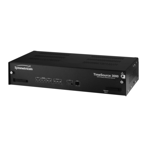
Page 16: Physical Description
Physical Description The TimeSource 3000 consists of a shelf, a plug-in card, an antenna, cables, hardware, and software. An optional factory- installed daughtercard may be included to provide eight additional T1 outputs, eight additional composite clock outputs, or two additional IRIG-B TOD timing outputs. -
Page 17: Functional Description
Functional Description Overview Figure 2 shows the main functions of the TimeSource 3000. The center of the TimeSource 3000 is the Ensemble Timing Generator, which uses the BesTime algorithm to analyze the phase and frequency relationships, individually and collectively, of the timing sources. - Page 18 Input #2 Extractor 8 Composite Clock Outputs Remote Clock Oscillator 2 IRIG-B Outputs Extractor Input #1 8 T1 Outputs Remote Clock Oscillator Extractor Input #2 Optional outputs –48 V B Power Power to Supply shelf –48 V A TimeSource 3000...
-
Page 19: Antenna
Antenna The antenna housing includes a volute antenna, GPS receiver, amplifier, and intermediate-frequency (IF) downconverter. The GPS Receiver extracts a clock signal from the GPS satellite signals. The receiver can process the signals from all satellites in view, while simultaneously using the Earth location of the receiver and other factors to determine an accurate clock signal. -
Page 20: Clock Extractors
T1 Outputs The BesTime Ensemble Timing Generator provides the timing for the T1 timing signal available at the T1 OUT A and B connectors in a framed, all-ones format, which can be set to ESF or D4 framing. TimeSource 3000... -
Page 21: Eight Additional T1 Outputs (Optional)
Eight Additional T1 Outputs (Optional) This option provides eight additional T1 outputs at the OPTIONS I/O wire-wrap pins. These outputs function the same as the standard T1 outputs. TOD Output The BesTime Ensemble Timing Generator provides the timing for the TOD timing signal available at the RJ-45 connector, which provides time code to devices compatible with NTP Type 4 or Cisco format. -
Page 22: Composite Clock Outputs (Optional)
TL1 messages reported via the communication ports. Ethernet TimeSource 3000 has one physical Ethernet port with six virtual ports to carry TL1 commands, responses, and autonomous messages between the TimeSource 3000 and an external terminal, or an Element Manager, or both. The user can configure the IP address, subnet mask, and gateway address for the Ethernet ports. - Page 23 Chapter Engineering & Ordering This chapter provides antenna installation guidelines, shelf mounting configurations, a parts list, and a list of user-supplied tools required for installation.
-
Page 24: Site Survey
Determine the cable length between the lightning suppressor and the shelf location determined in Steps 1 and 3. Determine the –48 V power source for the shelf. Determine if 5 MHz signals from a Symmetricom Digital Clock Distributor (DCD) Shelf will be used as remote oscillator inputs (optional). End of Procedure... -
Page 25: Lightning Suppressor Guidelines
Lightning Suppressor Guidelines • Mount the lightning suppressor within 15 feet of a valid, direct, low impedance, low resistance, earth ground connec- tion point. Valid earth grounds include the roof ring ground system, building structural steel, or a Central Office ground plate. -
Page 26: Antenna Location Guidelines
Signals closer to the horizon are often subject to multipath effects, which degrade the timing solution. The TimeSource 3000 can be set to ignore, or mask, all signals from the horizon to a chosen angle of elevation (mask angle). (See Figure 3.) - Page 27 Figure 3. Antenna Field of View No single obstruction more Antenna position than 12.5% of field of view Total obstructions no more than 25% of field of view Antenna field of view Obstructions toward pole if possible 10° 10° Mask angle* Mask angle* Horizon Equator...
- Page 28 2. Place the antenna high enough that the roof structure and tree are below the mask angle, and the water tower does not block more than 12.5 percent of the sky. TimeSource 3000...
- Page 29 Figure 4. Antenna Location Examples Antenna tower antenna Building location antenna (Note 1) Water location Roof tower (Note 2) structure Tree Antenna tower Location A Location B Note: The most important objects are within 1/4 mile (400 yards) of the antenna. Obstructions may include, but are not limited to, towers, buildings, other construction, trees, and high-voltage power lines.
- Page 30 Bracket Cable Mounting Pipe Conduit Heating 8 ft Ducts Rooftop 16 ft (10 ft minimum) Pipe clamped to wall Cable entry Building Wall Note: This is an example only. Not all parts are available from Symmetricom. TimeSource 3000...
- Page 31 • The minimum vertical distance above parapets, obstructions, or horizontal metallic reflective surfaces is 4 feet. • Do not locate the antenna within 30 degrees azimuth of the transmission direction of any transmitting antenna (to avoid overpowering the GPS reception, even though the transmit- ting antenna may operate at a different frequency).
-
Page 32: Cabling Considerations
• Any opening where conduit enters the building must be waterproofed per local company practices. • Treat all exposed connections with an electrically conductive anti-corrosion compound (Kopr-Shield or equivalent). Warning: Avoid small-radius turns and unnecessary turns. TimeSource 3000... -
Page 33: Standard Configuration
Two cables are required: one to connect the antenna to the lightning suppressor and another to connect the lightning suppressor to the TimeSource 3000 Shelf. Optionally, one length of coaxial cable may be ordered, which must be cut and prepared with end-connectors at the point where the suppressor is located. -
Page 34: Optional Configuration
If 5 MHz signals from a DCD Shelf are used as remote oscillator inputs, a 5 MHz Isolator Kit must be used between the DCD Shelves listed below and the TimeSource 3000 Shelf. Refer to Field Service Bulletin FSB 098-40620-19R2 for details. - Page 35 The isolation module is used to reduce potential noise coupling, and match impedances in the cables between the DCD master shelf and TimeSource 3000. It also converts the 5 MHz output from a square wave to a sine wave. The isolation module is installed between the TimeSource 3000 Shelf and the DCD master shelf.
-
Page 36: Rj-45-To-Db-25 Tod Converter
TOD converter, and two screws. Install the converter anywhere (for example, on unused space on a rack) within 1,000 cable feet of the TimeSource 3000 shelf, and within 50 cable feet of the device receiving the time code. The user must supply two cables. One cable is a Category 5 four- pair RS-422 cable, 1,000 feet maximum, with RJ-45 connectors on each end. -
Page 37: Antenna-To-Shelf Cabling
2. If desired, a single cable run can be made from the antenna to the TimeSource 3000 Shelf. The cable can then be cut at the lightning suppressor location, and TNC connectors attached to the cut ends of the cable. (The “xx” in the part number indicates the cable length –... - Page 38 RG-59/U Cable to cable) Lightning Suppressor (143-00018-01) and Mounting Bracket TNC Connector (070-00300-02) (Attached to cable) RG-59/U Cable(s) (060-72010-xx) Note 1 (Note 2) TNC Connector (Attached to cable) RG-59/U Cable TNC Connector (Attached to cable) TimeSource 3000 Shelf TimeSource 3000...
-
Page 39: Shelf Considerations
Figure 7C), or for flush mounting or 5 inch offset mounting in a 23 inch rack (Figure 7B and Figure 7D). Leave one RU (1.75 inches) of air space above the TimeSource 3000 Shelf for proper ventilation. Mount the shelf in the rack according to standard company practices. - Page 40 A. Flush mounting – 19 in. rack B. Flush mounting – 23 in. rack Rear of rack Rear of rack Top of shelf Top of shelf C. 5 in. offset – 19 in. rack D. 5 in. offset – 23 in. rack TimeSource 3000...
-
Page 41: Systems
Systems The TimeSource 3000 Systems available are listed below. With Two T1 Outputs This system (990-72010-01) includes: • TimeSource 3000 Shelf (090-72000-01) • TimeSource 3000 card (090-72010-01) • IF antenna assembly (090-72010-97) • Antenna mounting kit (093-00001-01) • Hardware kit (093-72010-97) includes:... -
Page 42: With Ten T1 Outputs
With Ten T1 Outputs This system (990-72010-02) includes: • TimeSource 3000 Shelf (090-72000-01) • TimeSource 3000 card with expansion T1 outputs (090- 72010-02) • IF antenna assembly (090-72010-97) • Antenna mounting kit (093-00001-01) • Hardware kit (093-72010-97) includes: - Lightning suppressor (143-00018-01) -
Page 43: With Two T1 And Eight Composite Clock Outputs
With Two T1 and Eight Composite Clock Outputs This system (990-72010-03) includes: • TimeSource 3000 Shelf (090-72000-01) • TimeSource 3000 card with composite clock outputs (090-72010-03) • IF antenna assembly (090-72010-97) • Antenna mounting kit (093-00001-01) • Hardware kit (093-72010-97) includes:... -
Page 44: With Two T1 And Two Irig-B Tod Outputs
With Two T1 and Two IRIG-B TOD Outputs This system (990-72010-05) includes: • TimeSource 3000 Shelf (090-72000-01) • TimeSource 3000 card with IRIG-B TOD outputs (090-72010-05) • IRIG-B BNC adapter (090-72100-06) • Two right-angle BNC connectors (121-00530-01) • IF antenna assembly (090-72010-97) •... -
Page 45: User-Supplied Tools And Materials
User-Supplied Tools and Materials For Antenna Installation Ensure that the user-supplied tools and materials listed below are on hand for installation of the antenna. • 1 inch diameter galvanized metal pipe, used as a mast to mount the antenna. Mast should be long enough to position the antenna above any metal object on the roof. -
Page 46: For Shelf Installation
• 16 AWG green insulated ground wire • 16 AWG red insulated wire • 16 AWG black insulated wire • T1 cables For Shelf Installation Ensure that a Phillips-head screwdriver is on hand for installing the TimeSource 3000 Shelf in a rack. TimeSource 3000... -
Page 47: Installation
Installation Chapter This chapter provides the steps required for installation and power-up. - Page 48 Unpacking Install the TimeSource 3000, using steps in the order given in this chapter. If any difficulties are encountered during the installation process, contact Symmetricom’s Customer Technical Assistance Center (CTAC). Refer to the Technical Assistance section of the Troubleshooting chapter for telephone numbers.
-
Page 49: Antenna
Antenna Installation procedures are to follow local company procedures and the Installation Job Specification. Procure the user supplied tools and materials listed in the engineering and ordering chapter. Prior to installing the antenna, the site, antenna location, lightning suppressor location, cable route, and all other details should be planned. - Page 50 Antenna Mounting Hardware (112-00002-01) TNC Connector (Attached RG-59/U Cable to cable) Lightning Suppressor (143-00018-01) and Mounting Bracket TNC Connector (070-00300-02) (Attached to cable) Ground TNC Connector (Attached to cable) RG-59/U Cable TNC Connector (Attached to cable) TimeSource 3000 Shelf TimeSource 3000...
- Page 51 Procedure B. Antenna Mounting and Cable Connection Step Procedure Attach the antenna mounting bracket to a pipe (1 in. diameter) or a wood post. • If mounting the bracket to a pipe, slide the two V-bolts over the pipe, and through the mounting bracket slots;...
- Page 52 15 ft of the chosen valid earth ground. If the mounting plate is to be installed in a nonmetallic junction box, perform the installation, and bolt the assembly near the chosen valid earth ground. TimeSource 3000...
- Page 53 Connect a cable to the antenna, route the cable through the conduit, and connect the cable to the lightning suppressor. Connect a cable to the lightning suppressor, route the cable through the conduit into the building, and route the cable through the building to the TimeSource 3000 Shelf location. Installation...
- Page 54 Install fire-stopping material in all holes opened in the roof and/or walls during this procedure. Check all connections for tightness to prevent arcing and intermittent operation. Coat all exposed connectors with an electrically conductive antioxidant compound (e.g., Kopr-Shield spray). End of Procedure TimeSource 3000...
-
Page 55: Shelf
Figure 9C), or for flush mounting or 5 inch offset mounting in a 23 inch rack (Figure 9B and Figure 9D). Leave 1 RU (1.75 inches) of air space above the TimeSource 3000 Shelf for proper ventilation. Mount the shelf in the rack according to standard company practices. - Page 56 A. Flush mounting – 19 in. rack B. Flush mounting – 23 in. rack Rear of rack Rear of rack Top of shelf Top of shelf C. 5 in. offset – 19 in. rack D. 5 in. offset – 23 in. rack TimeSource 3000...
-
Page 57: Cabling
Power and Signal Cabling Warning: The circuitry on the plug-in circuit board is subject to electrostatic discharge (ESD) damage. Be sure to wear an ESD wrist strap when making connections to the rear panel. Failure to observe this warning may result in equipment damage. - Page 58 Time of Day T1 Inputs T1 Outputs Battery B Battery A A & B & Frame Port 2 A & B & Frame Ground Ground Ethernet Expansion Bus (TB2) (TB1) (Reserved for future use) Figure 10. Front Panel Connector Craft TimeSource 3000...
-
Page 59: Frame Ground
Frame Ground Frame ground connections are made on power terminal blocks TB1 and TB2. Refer to Warning: for the location of the terminals on the rear of the shelf, and refer to Figure 11 for the terminal connections. Figure 11. Battery Connections –48V –48V A. - Page 60 Kopr-Shield spray. Crimp the supplied spade lug to the other end of the 16 AWG wire, and connect it to the FRM terminals on TB1 and TB2 (Figure 11). TimeSource 3000...
-
Page 61: Power
R TN B terminal on TB2. Replace the protective covers on the terminal blocks. Caution: Do not apply the office battery to the TimeSource 3000 at this time. Note: Two separate office battery supplies (battery A and battery B) are recommended. -
Page 62: Alarms Output
Figure 12. Alarm Connections GPS Antenna Use the supplied 90 degree adapter to connect the coaxial cable from the lightning suppressor to the TNC connector labeled GPS ANT. Refer to Warning: for the connector location. TimeSource 3000... -
Page 63: Additional T1 Outputs
Additional T1 Outputs If using the additional T1 outputs, connect the optional eight T1 outputs at the I/O Options wire-wrap pins. See Warning: for the connector location, and Figure 13 for the connections. The additional T1 outputs option is indicated by the 72010-02 part number on the shelf front panel. -
Page 64: Irig-B Tod Outputs
The IRIG-B TOD pouts option is indicated by the 72010-05 part number on the shelf front panel. Follow Procedure C to install the IRIG-B BNC adapter, and make the IRIG-B TOD connections. Figure 14. IRIG-B TOD BNC Output Connections Screws (4 places) Output 1 Output 2 TimeSource 3000... - Page 65 Procedure C. IRIG-B TOD Output Installation Step Procedure Position the IRIG-B adapter onto the rear of the shelf so that the OPTIONS I/O wire- wrap pins project through holes in the adapter card. Secure the adapter onto the shelf, using the four screws integral to the adapter (see Figure 14).
-
Page 66: Expansion Bus
Note: The isolation module must be mounted on the rack, in close proximity to the DCD Shelf, whether or not the TimeSource 3000 is installed in a collocated or non-collocated location from the DCD Shelf. Attaching the isolation module (to the rack) grounds the module to rack frame ground. - Page 67 DCD Shelf backplane to the TO DCD SHELF end of the isolation module (refer to Table B and Figure 15). Use the 6 ft coax cable, and connect from the REM OSC A connector on the TimeSource 3000 Shelf to the TO LPR end of the isolation module (refer to Figure 15). Note: To provide suppor t and minimize cable clutter, route cable to the right or left, and secure to the cable suppor t bar, using tie wraps.
- Page 68 Table B. DCD Connections to the TimeSource 3000 From DCD Shelf To TimeSource 3000 Shelf Type Connector Label Connector DCD-ST2 5 MHZ OUTPUT A REM OSC A 5 MHZ OUTPUT B REM OSC B DCD-419 NOT LABELED REM OSC A...
- Page 69 Figure 15. DCD Shelf, Isolation Module, and TimeSource 3000 Connections From REM OSC A or B From REM OSC A or B on TimeSource 3000 Shelf on TimeSource 3000 Shelf TO LPR 6 ft cable 6 ft cable to TimeSource 3000...
-
Page 70: Pps Output
10 MHz output signal. See Warning: for the connector location. Ethernet Connect a user-supplied Ethernet cable from the network to the 10base-T Ethernet connector labeled ETHER. See Figure Warning: for the connector location, and Table C for the connector pinouts. TimeSource 3000... - Page 71 Table C. Ethernet 10base-T RJ-45 Connector Pinouts Signal Abbreviation Direction Transmit data + TXD + From TimeSource 3000 Transmit data – TXD – From TimeSource 3000 Receive data + RXD + To TimeSource 3000 — — — — — —...
-
Page 72: Time Of Day Output
Table D for the connector pinouts. Table D. TOD Connector Pinouts Signal Abbreviation Direction 1 pps A TOD PPS + From TimeSource 3000 1 pps B TOD PPS – From TimeSource 3000 12 V power source TOD P12V —... - Page 73 Notes: 1. Due to distance constraints, the converter must be placed no more than 1000 ft from the TimeSource 3000 Shelf, and no more than 50 ft from the device receiving the time code. 2. The converter dimensions are 3 in. by 2.5 in by 1 in.
- Page 74 Screws Converter Converter (supplied) Figure 17. RJ-45–to–DB-25 TOD Converter Connections DB-25 Connector RJ-45 To device Connector receiving 50 ft Converter To TimeSource time code max. 1000 ft 3000 max. TimeSource 3000...
- Page 75 Table E. Converter DB-25 Connector Pinouts Signal Frame ground Data output (RS-232) 1 pps (RS-232) Signal ground Note: Pins not listed are reserved for future use. Installation...
-
Page 76: T1 Inputs
The shield pin is capacitively coupled to ground, therefore, the shield must be connected at the source end. The shield may also be connected at the TimeSource 3500 end for additional longitudinal noise protection. Figure 18. T1 Input Connections SPAN IN TimeSource 3000... -
Page 77: T1 Outputs
T1 Synchronization Outputs Warning: Because the T1 output circuits do not provide lightning protection, do not connect the T1 output line directly to an outside facility. Failure to observe this warning may result in equipment damage. Connect the T1 synchronization outputs at the wire-wrap pins labeled T1 OUT A and T1 OUT B. -
Page 78: Communication Port 1
3. Be sure the other equipment receives data from the transmitting pin, and transmits data to the receiving pin. Table F. COM1 Pinouts Signal Abbreviation Direction Transmit data From TimeSource 3000 Receive data To TimeSource 3000 Request to send From TimeSource 3000 Clear to send To TimeSource 3000... -
Page 79: Communication Port 2
3. Be sure the other equipment receives data from the transmitting pin, and transmits data to the receiving pin. Table G. COM2 Pinouts Signal Abbreviation Direction Transmit data From TimeSource 3000 Receive data To TimeSource 3000 Signal ground — Data terminal ready From TimeSource 3000... -
Page 80: Craft Port
3. Be sure the other equipment receives data from the transmitting pin, and transmits data to the receiving pin. Table H. Craft Pinouts Signal Abbreviation Direction Transmit data From TimeSource 3000 Receive data To TimeSource 3000 Signal ground — Data terminal ready From TimeSource 3000 Note: Pins not listed are reserved for future use. -
Page 81: Power-Up
• Laptop computer with communications software (e.g., Windows Hyperterminal, ProComm Plus, CrossTalk) On the computer connected to the TimeSource 3000, start a VT100 terminal mode session via communication software that supports the Y-modem protocol (such as Hyperterminal, or a commercial package such as PROCOMM PLUS or CrossTalk). - Page 82 Pull out the latching levers at each end of the front panel of the TimeSource 3000 card so that the levers are pointing directly out from the front panel.
- Page 83 Procedure Install the battery source fuse in the rack fuse bay that supplies power to the TimeSource 3000. The TimeSource 3000 enters its warm-up mode when power is applied. During the warm-up period, the following conditions exist: • Status GPS lamp is green •...
- Page 84 If UTC time is not desired, skip to Step18. Use the Edit Date command to set the system for UTC time. ED-DAT:::<ctag>::yyyy-mm-dd:MODE=UTC; yyyy = year (yyyy = 1998 to 2096) = month (mm = 01 to 12) = day (dd = 01 to 31) Example command to set UTC time: ED-DAT:::123::2000-06-15:MODE=UTC; TimeSource 3000...
- Page 85 Procedure F. Power-Up (cont’d) Step Procedure Use the Retrieve Equipment command to identify how the inputs are provisioned. RTRV-EQPT::ALL:<ctag>; Note: Note the results of the Retrieve Equipment command to set the remaining parameters in this procedure. The possible parameter settings are shown below. Parameter Definition FREQ=5...
- Page 86 T1 output, and set the mode for each T1 output during an alarm. ED-EQPT::T1-x:<ctag>:::FRAMING=y,ALMOUT=z; = T1 output (x = A or B) = framing format (y = ESF or D4) = T1 output during alarm (z = AIS, SQUELCH, or SSM) (for SSM, framing format must be ESF) TimeSource 3000...
- Page 87 Step 26. Use the Edit Equipment command to set the length of cable between the antenna and the TimeSource 3000 Shelf. This number should have been recorded during installation. Use the same command to set the antenna elevation mask angle.
- Page 88 If not using Ethernet, go to Step 32. Use the Edit Equipment command while connected to COM1, COM2, or the CRAFT port to set the IP address, subnetwork mask, and gateway address for the current TimeSource 3000 unit, as required for proper operation in the managed element network. (These parameters affect all Ethernet ports.
- Page 89 Procedure F. Power-Up (cont’d) Step Procedure Ports 5001, 5002, 5003 and 5004 on the TimeSource 3000 are used as though they were serial TL1 communication ports. The following values are set at the factory and appear at reset: MONMSG=INH (monitors only the current port for messages)
- Page 90 Element Manager, skip to Step 31. Use the Edit Equipment command to set the IP address and port address of the Element Manager. Port 5550 connects to this address when the TimeSource 3000 develops a TL1 autonomous message, sends any messages, and closes the connection. An alternate Element Manager may be set up in case port 5550 cannot make a connection to the primary Element Manager.
- Page 91 Procedure F. Power-Up (cont’d) Step Procedure Use the Edit Communications command to set the communications parameters of port 5551. An Element Manager connects to port 5551 for TL1 command and response messages. The following values for port 5551 are set at the factory and appear at reset: MONMSG=INH (monitors only the current port for messages) KEEPALIVE=0 (does not send a COMPLD message to keep connection open)
- Page 92 Steady state operation is indicated by the clearing of the “settling period” event. 3. The TimeSource 3000 develops and sends timing within the PRS specification during steady state operation and during any event (other than settling period) or minor alarm, but not during a major or critical alarm.
- Page 93 Factory-Set Values The parameter values initially set at the factory are shown in Table I. Table I. Parameter Factory Settings <aid> Parameter Setting TS3000 FREQ=5MHz TOD=NONE ALMCOND=ALW IPNE=0.0.0.0 IPSUBNET=255.255.255.255 IPGATE=0.0.0.0 IPEM1=0.0.0.0 IPEM1PORT=0 IPEM2=0.0.0.0 IPEM2PORT=0 IPINACT=0 ANTCBLDLY=0 ANTELEVMASK=10 RO-A, RO-B ENSEMBLER=INH MONITOR=INH SPAN-A, SPAN-B ENSEMBLER=INH...
- Page 94 COMPRI=ALW1 AUTOLOGOFF=0 HWCONTROL=INH SWCONTROL=INH PARITY=NONE STOP=1 COM-5001, MONMSG=INH COM-5002, KEEPALIVE=0 COM-5003, ENDOF TEXT=00 COM-5004 ECHO=ALW COMPRI=ALW1 AUTOLOGOFF=0 SWCONTROL=INH COM-5551 MONMSG=INH KEEPALIVE=0 ENDOFTEXT=00 ECHO=INH COMPRI=ALW1 AUTOLOGOFF=0 SWCONTROL=INH OPT-1, OPT-2, FRAMING=ESF OPT-3, OPT-4, ALMOUT=AIS OPT-5, OPT-6, OPT-7, OPT-8 (990-72010-02 only) TimeSource 3000...
-
Page 95: Tl1 Reference
TL1 Reference This chapter provides information for using the TL1 language. Chapter... - Page 96 The following symbols are used in the input and response messages: encloses an optional parameter encloses a group of parameters, at least one of which must be entered separates alternatives in a group of parameters, at least one of which must be entered TimeSource 3000...
- Page 97 indicates a space (used in the description of the response format, but not used in the command responses) – separates command code fields separates parameter blocks separates parameters within a block terminates a command, and causes execution " " encloses text to be parsed by a machine /* */ encloses comments for humans <...
-
Page 98: Command Format
Entering a semicolon at the end of the command indicates that the command statement is completed to the interpreter, and executes the command. Figure 20. Command Format Parameter Block, with parameters separated by a comma Null Parameter Fields Block command-code:[<tid>]::<ctag>::<date>,<time>; Terminating Command Optional Parameter Semicolon Code Parameter Block TimeSource 3000... -
Page 99: Response Format
Response Format When a command is received and processed, a response is returned. All responses include a source identifier (<sid>), the date, the time, an M to indicate that it is a response to a command, and the correlation tag (<ctag>) that was entered with the command. - Page 100 Figure 22. Deny Response Format ^^^<sid>^<date>^<time> M^^<ctag>^DENY ^^^<errcde> /* <error message> */ /*LINK:<link>,CMD:<command>*/ TimeSource 3000...
-
Page 101: Parameters
Parameters The parameters that may be used in commands, responses, and messages are defined in Table J. When a parameter uses the same values in every instance, those values are listed with the parameter in the table. When the context requires different values for a parameter, the value is listed with the parameter in the applicable commands, responses, and messages. - Page 102 Error code text message. <link> Communication link identifier. <modifier> Equipment initiating the alarm or event message, which is one of the following: TS3000 = system software = GPS receiver software RO-x = remote oscillator input SPAN-x = T1 span input TimeSource 3000...
- Page 103 Private identifier, factory-set to “TS3000!!”. It is the initial password for the TELECOM <uid>. Passwords are encrypted when stored in the TimeSource 3000, and are never transmitted from the shelf. The pid contains a case-insensitive string of 8 to 10 ASCII characters, and must include at least one letter, one numeral, and one special character from the following: ! @ $ % * ( ) + ’...
- Page 104 Definition <tid> Target identifier which identifies the equipment (TimeSource 3000) to which the command is directed. The tid must be a valid TL1 identifier of a maximum of 20 characters (limited to letters, digits, and hyphens) beginning with a letter. The <tid>...
-
Page 105: Autonomous Messages
Autonomous Messages Autonomous messages are sent out when an alarm or event occurs. Two types of autonomous messages are used: • Report Alarm: reports alarms • Report Event: reports events that are not alarms, or that have not yet become alarms Autonomous messages are listed on the following pages. -
Page 106: Report Alarm
Report Alarm This autonomous message appears when an alarm is raised, and appears again when the alarm is cleared. Message: <sid> <date> <time> <almcde> <atag> REPT ALM <modifier> "<aid>:<ntfcncde>,<condtype>,<srveff>, <ocrdat>,<ocrtm>,,,:\"<conddescr>\ "[:<dgntype>]" Note: Refer to Table J for parameter definitions. TimeSource 3000... -
Page 107: Report Event
Report Event This autonomous message appears when an event is raised, and again when the event is cleared; also appears when a transient event occurs. An event is a state of the TimeSource 3000 that does not cause an alarm. Message: <sid>... -
Page 108: Factory-Set Values
The parameter values initially set at the factory are shown in Table K. Table K. Parameter Factory Settings <aid> Parameter Setting TS3000 FREQ=5MHz TOD=NONE ALMCOND=ALW IPNE=0.0.0.0 IPSUBNET=255.255.255.255 IPGATE=0.0.0.0 IPEM1=0.0.0.0 IPEM1PORT=0 IPEM2=0.0.0.0 IPEM2PORT=0 IPINACT=0 ANTCBLDLY=0 ANTELEVMASK=10 RO-A, RO-B ENSEMBLER=INH MONITOR=INH SPAN-A, SPAN-B ENSEMBLER=INH MONITOR=INH SSM=INH T1-A, T1-B FRAMING=ESF ALMOUT=AIS TimeSource 3000... - Page 109 Table K. Parameter Factory Settings (cont’d) <aid> Parameter Setting COM-1, COM-2, BAUD=9600 COM-3 MONMSG=INH KEEPALIVE=0 ENDOFTEXT=00 ECHO=ALW COMPRI=ALW1 AUTOLOGOFF=0 HWCONTROL=INH SWCONTROL=INH PARITY=NONE STOP=1 COM-5001, MONMSG=INH COM-5002, KEEPALIVE=0 COM-5003, ENDOF TEXT=00 COM-5004 ECHO=ALW COMPRI=ALW1 AUTOLOGOFF=0 SWCONTROL=INH COM-5551 MONMSG=INH KEEPALIVE=0 ENDOFTEXT=00 ECHO=INH COMPRI=ALW1 AUTOLOGOFF=0 SWCONTROL=INH...
-
Page 110: Tasks/Commands
Enter a new user and configure the new user’s Enter User Security user name, password, and access level Reset to zero all performance monitoring Initialize Register parameters associated with a given aid TimeSource 3000... - Page 111 Table L. Commands for Tasks (cont’d) Page Task Command Reset the system processor or GPS receiver Initialize System processor Deactivate the audible office alarm Operate Alarm Cutoff All Display current system alarms Retrieve Alarm All Display current alarms for specific equipment Retrieve Alarm Equipment Display current communication port parameter Retrieve Communication...
-
Page 112: Commands
Commands The commands used with the TimeSource 3000 are listed on the following pages. After the command name, a definition of the command is given. The definition is followed by the actual command, followed by the variables that can be used with the command. -
Page 113: Activate User
Activate User This command logs the user onto the system, and begins a session. The factory-set user name is “TELECOM”, and the factory-set password is “TS3000!!”. The user name and password are not case sensitive (either uppercase or lowercase can be used). The command format is: ACT-USER:[<tid>]:<uid>:<ctag>::<pid>;... -
Page 114: Cancel User
The user name is not case sensitive, but must otherwise be entered exactly as assigned. The command format is: CANC-USER:[<tid>]:<uid>:<ctag>; Parameter Parameter Description <uid> Assigned user name Command Example: CANC-USER::TELECOM:<ctag>; Response Format: <sid> <date> <time> <ctag> COMPLD /*LINK:<link>,CMD:<command>*/ TimeSource 3000... -
Page 115: Copy Memory
1. Clear any existing alarms before using this command. 2. The database is automatically copied to nonvolatile memory once per hour. However, if power to the TimeSource 3000 is interrupted before the automatic copying occurs, changes made since the last automatic copy will be lost. To avoid the... - Page 116 Copy Memory (cont’d) Command Example: CPY-MEM::TS3000:<ctag>::AUX,,WKG:PGM; Response Format: <sid> <date> <time> <ctag> COMPLD /*LINK:<link>,CMD:<command>*/ To copy a database from volatile to nonvolatile memory within the TimeSource 3000, the command format is: CPY-MEM:[<tid>]:<aid>:<ctag>::WKG,,AUX:DATA; Item Addressed TS3000 System software Command Example: CPY-MEM::TS3000:<ctag>::WKG,,AUX:DATA; Response Format: <sid>...
-
Page 117: Delete Equipment
Delete Equipment This command deletes the specified equipment from the database, removes the input from the ensembling algorithm, and stops the monitoring for that input. Alarms are not reported for deleted equipment. The command format is: DLT-EQPT:[<tid>]:<aid>:<ctag>; a Value Item Addressed RO-a Remote oscillator A input Remote oscillator B input... -
Page 118: Delete User Security
Delete User Security This command allows a system administrator to delete a user. The command format is: DLT-USER-SECU:[<tid>]:<uid>:<ctag>; Parameter Parameter Description <uid> Assigned user name Command Example: DLT-USER-SECU::TELECOM:<ctag>; Response Format: <sid> <date> <time> <ctag> COMPLD /*LINK:<link>,CMD:<command>*/ TimeSource 3000... -
Page 119: Edit Communication
Edit Communication This command changes communication port parameters. The command format is: ED-COM:[<tid>]:<aid>:<ctag>:::<spec_block>; Value Item Addressed COM-a a = 1 Serial communication port 1 (COM1) a = 2 Serial communication port 2 (COM2) a = 3 Serial communication port 3 (Craft) a = 5001 Ethernet user interface por t 5001 (Note 1) a = 5002 Ethernet user interface por t 5002 (Note 1) a = 5003 Ethernet user interface por t 5003 (Note 1) - Page 120 = INH Closes connection, logs off any user (if logged on), and keeps por t from use. Releases a telnet session from an Ethernet port (a por t cannot close itself) TimeSource 3000...
- Page 121 Edit Communication (cont’d) Parameter Value Description COM-a AUTOLOGOFF=b b = 1 to 255 Inactive minutes until the unit logs off (cont’d) the user, keeping the connection open b = 0 Autologoff is disabled HWCONTROL=b b = ALW Serial por t CTS/RTS flow control is (See Note 4) enabled b = INH...
- Page 122 (1, 2, and 3). 4. Flow control is not implemented on communication port 3 (Craft port). 5. XON/XOFF flow control is simulated for Ethernet ports. Command Example: ED-COM::COM-1:<ctag>:::BAUD=9600,MONMSG=ALW, KEEPALIVE=30,ENDOFTEXT=0,ECHO=ALW, COMPRI=ALW1,AUTOLOGOFF=30,HWCONTROL=ALW, SWCONTROL=ALW,PARITY=NONE,STOP=1; Response Format: <sid> <date> <time> <ctag> COMPLD /*LINK:<link>,CMD:<command>*/ TimeSource 3000...
-
Page 123: Edit Date
Edit Date This command changes the system date and time. The command format is: ED-DAT:[<tid>]::<ctag>::<date>,[<time>] :[MODE=a]; Parameter Value Parameter Description date in the format a = <year> 4-digit year a-b-c b = 01 to 12 Month c = 01 to 31 time in the format a = 00 to 23 Hour of the day... - Page 124 Edit Date (cont’d) Example to set date without changing time or mode: ED-DAT:::<ctag>::2000-08-13; Example to change to local time: ED-DAT:::<ctag>::2000-08-13,07-00-00:MODE=LOCAL; Example to change from local to UTC time: ED-DAT:::<ctag>::2000-08-13:MODE=UTC; Response Format: <sid> <date> <time> <ctag> COMPLD /*LINK:<link>,CMD:<command>*/ TimeSource 3000...
-
Page 125: Edit Equipment
Edit Equipment This command changes equipment parameters. Additionally, this command can cause an input to be ensembled. The command format is: ED-EQPT:[<tid>]:<aid>:<ctag>:::<spec_block>; a Value Item Addressed TS3000 — System-wide configuration — GPS configuration RO=a Remote oscillator A input Remote oscillator B input SPAN=a T1 span A input T1 span B input... - Page 126 Alarm conditioning for T1, TOD, IRIG-B, and composite clock outputs is disabled IPNE=a.b.c.d a = 0 to 255 IP address of this TimeSource 3000 (See Note 1) (command must be sent from COM1, b = 0 to 255 COM2, or Craft por t to set this...
- Page 127 = 0 to 255 Default gateway IP address for this (cont’d) (See Note 1) TimeSource 3000 (command must be b = 0 to 255 sent from COM1, COM2, or Craft por t c = 0 to 255 to set this parameter) d = 0 to 255 IPEM1=a.b.c.d...
- Page 128 1. This parameter affects all Ethernet ports. Close the Ethernet ports and log off all users before issuing a command with this parameter. 2. Port 5550 makes a connection to this element manager to send TL1 autonomous messages, and closes the connection when the transmission is complete. TimeSource 3000...
- Page 129 3. Port 5551 accepts a connection from this element manager for TL1 commands and responses. 4. A remote oscillator must have been put into service before using the ENT -EQPT command before setting the ENSEMBLER parameter. 5. A span must have been put into service using the ENT -EQPT command before setting the ENSEMBLER and SSM parameters.
-
Page 130: Enter Equipment
The Delete Equipment command must be used to take an input out of service. The command format is: ENT-EQPT:[<tid>]:<aid>:<ctag>[:::<spec_block>]; a Value Item Addressed RO-a Remote oscillator A input Remote oscillator B input SPAN-a T1 span A input T1 span B input TimeSource 3000... - Page 131 Enter Equipment (cont’d) The parameters which can be entered in the <spec_block> are listed below. For any specific <aid> entered in a command, only certain parameters are valid. For each valid parameter, choose the appropriate value of “b” from the “b Value” column. When entering multiple parameters, separate the parameters with commas.
-
Page 132: Enter User Security
Access level (1 to 5). Levels 1 to 4 do not allow the user to enter or delete users. Level 5 allows the user to enter or delete users. Command Example: ENT-USER-SECU::TELECOM:<ctag>::TS3000!!,,1; Response Format: <sid> <date> <time> <ctag> COMPLD /*LINK:<link>,CMD:<command>*/ TimeSource 3000... - Page 133 Initialize Register This command resets to zero all the performance monitoring associated with the entered aid. The command can be used to reset either span independently or both spans at the same time. The command format is: INIT-REG-EQPT:[<tid>]:<aid>:<ctag>::ALL; Value Item Addressed SPAN-a a = A T1 span A input...
-
Page 134: Initialize System
20 minutes if ALMOUT is SQUELCH, or unstable outputs if ALMOUT is not SQUELCH. The command format is: INIT-SYS:[<tid>]:<aid>:<ctag>::1; Item Addressed TS3000 System software GPS receiver software Response Format: <sid> <date> <time> <ctag> COMPLD /*LINK:<link>,CMD:<command>*/ TimeSource 3000... -
Page 135: Operate Alarm Cutoff All
Operate Alarm Cutoff All This command deactivates (silences) the audible office alarm. The command format is: OPR-ACO-ALL:[<tid>]:ALL:<ctag>; Response Format: <sid> <date> <time> <ctag> COMPLD /*LINK:<link>,CMD:<command>*/ TL1 Reference... -
Page 136: Retrieve Alarm All
<sid> <date> <time> <ctag> COMPLD /*LINK:<link>,CMD:<command>*/ If there is at least one alarm: <sid> <date> <time> <ctag> COMPLD "<aid>:<ntfcncde>,<condtype>,<srveff>, <ocrdat>,<ocrtm>,,:\"<conddescr>\""... /*LINK:<link>,CMD:<command>*/ Note: Refer to the Troubleshooting chapter for a list of all <conddescr> messages, and the recommended action. TimeSource 3000... -
Page 137: Retrieve Alarm Equipment
Retrieve Alarm Equipment This command displays current alarms for the specified equipment. The command format is: RTRV-ALM-EQPT:[<tid>]:<aid>:<ctag>; x Value Item Addressed TS3000 — System (all TS3000 alarms) SPAN-x T1 span A input T1 span B input RO-x Remote oscillator A input Remote oscillator B input —... - Page 138 <sid> <date> <time> <ctag> COMPLD /*LINK:<link>,CMD:<command>*/ If there is at least one alarm: <sid> <date> <time> <ctag> COMPLD "<aid>:<ntfcncde>,<condtype>,<srveff>, <ocrdat>,<ocrtm>,,:\"<conddescr>\""... /*LINK:<link>,CMD:<command>*/ Note: Refer to the Troubleshooting chapter for a list of all <conddescr> messages, and the recommended action. TimeSource 3000...
-
Page 139: Retrieve Communication
Retrieve Communication This command displays communication port parameter settings. The command format is: RTRV-COM:[<tid>]:<aid>:<ctag>; Value Item Addressed COM-a a = 1 Serial communication port 1 a = 2 Serial communication port 2 a = 3 Serial communication port 3 a = 5001 Ethernet user interface por t 5001 a = 5002 Ethernet user interface por t 5002... - Page 140 = ALW2 TL1 commands and responses, sends autonomous messages whether or not logged on a = INH Closes connection, logs off a user (if logged on), and keeps port from use (a port cannot close itself) TimeSource 3000...
- Page 141 Retrieve Communication (cont’d) Parameter Value Parameter Description AUTOLOGOFF=a a = 1 to 255 Inactive minutes until the unit logs off the user, keeping the connection open a = 0 Autologoff is disabled SWCONTROL=a a = ALW XON/XOFF flow control is enabled a = INH XON/XOFF flow control is not enabled HWCONTROL=a...
-
Page 142: Retrieve Condition All
<sid> <date> <time> <ctag> COMPLD /*LINK:<link>,CMD:<command>*/ If there is at least one alarm or event: <sid> <date> <time> <ctag> COMPLD "<aid>:<ntfcncde>,<condtype>,<srveff>, <ocrdat>,<ocrtm>,,,:\"<conddescr>\""... /*LINK:<link>,CMD:<command>*/ Note: Refer to the Troubleshooting chapter for a list of all <conddescr> messages, and the recommended action. TimeSource 3000... -
Page 143: Retrieve Condition Equipment
Retrieve Condition Equipment This command displays current alarms and events for the specified equipment. RTRV-COND-EQPT:[<tid>]:<aid>:<ctag>; x Value Item Addressed TS3000 — System SPAN-x T1 span A input T1 span B input RO-x Remote oscillator A input Remote oscillator B input —... - Page 144 <sid> <date> <time> <ctag> COMPLD /*LINK:<link>,CMD:<command>*/ If there is at least one alarm: <sid> <date> <time> <ctag> COMPLD "<aid>:<ntfcncde>,<condtype>,<srveff>, <ocrdat>,<ocrtm>,,,\"<conddescr>\""... /*LINK:<link>,CMD:<command>*/ Note: Refer to the Troubleshooting chapter for a list of all <conddescr> messages, and the recommended action. TimeSource 3000...
-
Page 145: Retrieve Equipment
Retrieve Equipment This command displays parameter settings for the specified equipment. The command format is: RTRV-EQPT:[<tid>]:<aid>:<ctag>; x Value Item Addressed — All aids for this command TS3000 — System — GPS receiver RO-x Remote oscillator A input Remote oscillator B input SPAN-x Span A input Span B input... - Page 146 Retrieve Equipment (cont’d) Response Format: <sid> <date> <time> <ctag> COMPLD "<aid>::::<spec_block>"... /*LINK:<link>,CMD:<command>*/ The parameters which may be displayed in the <spec_block> are listed below. TimeSource 3000...
- Page 147 Retrieve Equipment (cont’d) Parameter Value Parameter Description — — Display all settings TS3000 FREQ=a Frequency for both remote oscillator inputs is 5 MHz a=10 Frequency for both remote oscillator inputs is 10 MHz TOD=a a=CISCO Serial message sent is Cisco format a=NTP4 Serial message sent is NTP Type 4 format...
- Page 148 100-ms units (0 to 10,000, where 0 deactivates the timer, for example, 100 = 10 s) ANTCBLDLY=a a=0 to 330 Antenna cable length (meters) ANTELEVMASK=a a=0 to 45 Antenna elevation mask angle (degrees) TimeSource 3000...
- Page 149 Retrieve Equipment (cont’d) Parameter Value Parameter Description RO-x ENSEMBLER=a a=ALW Remote oscillator is ensembled a=INH Remote oscillator is not ensembled MONITOR=a a=ALW Remote oscillator is monitored a=INH Remote oscillator is not monitored SPAN-x ENSEMBLER=a a=ALW T1 span is ensembled a=INH T1 span is not ensembled MONITOR=a a=ALW...
-
Page 150: Retrieve Gps Status
Retrieve GPS Status This command displays the position of the GPS receiver, UTC time, and status information for each of the GPS satellites in view. The command format is: RTRV-GPS-STAT:[<tid>]:GPS:<ctag>; Response Format: <sid> <date> <time> <ctag> COMPLD "GPS:LAT=x,LONG=x,<alt>,<utc>” "GPS:SAT-x,USE=X,CNO=x,ELEV=x,AZ=x,LOCK=x” /*LINK:<link>,CMD:<command>*/ TimeSource 3000... - Page 151 Retrieve GPS Status (cont’d) Parameter Value Description LAT=a Current latitude nor th in degrees, dd.mm.fffN minutes, and decimal-fractions of a minute a = dd.mm.fffS Current latitude south in degrees, minutes, and decimal-fractions of a minute LONG=a Current longitude east in degrees, ddd.mm.fffE minutes, and decimal-fractions of a minute...
-
Page 152: Retrieve Inventory
Retrieve Inventory This command displays information about the specified equipment. RTRV-INVENTORY:[<tid>]:TS3000:<ctag>; Response Format: <sid> <date> <time> <ctag> COMPLD "TS3000::::<CARD=TS3000>, MACID=a, TYPE=a, PART=a, SERIAL=a, SOFTVER_TS3000=a, SOFTVER_GPS=a, SOFTVER_DEV=a" /*LINK: x, CMD:<command>*/ TimeSource 3000... - Page 153 TYPE=a a = NO OPTION TimeSource 3000 (standard) (990-72010-01 BOARD systems) a = T1 OPTION TimeSource 3000 with eight additional T1 BOARD outputs (990-72010-02 systems) a = CCK OPTION TimeSource 3000 with eight composite clock BOARD outputs (990-72010-03 systems)
- Page 154 Retrieve Performance Monitoring This command retrieves the performance monitoring data from the TimeSource 3000. This data includes MTIE, TDEV, Phase 1S, and Phase 1M. For current 24 hour data, MTIE, TDEV, and Phase 1S data are grouped every 15 minutes. In addition, there are 7 daily summaries of MTIE, TDEV, and Phase 1M.
- Page 155 Retrieve Performance Monitoring (cont’d) Parameter Value Description SPAN-a a = A E1 span A input a = B E1 span B input <montype> MTIE MTIE data reported TDEV TDEV data reported PHASE1S 1-second phase data repor ted PHASE1M 1-minute phase data repor ted <mondat>...
- Page 156 To select one daily summary, enter mondat, but do not enter montm. Any mondat not in the previous 7 day window is denied. • Entering the date or time is optional. Type a semicolon after montype to display the most recent statistics for the specified montype. TimeSource 3000...
- Page 157 Retrieve Performance Monitoring (cont’d) Parameter Value Description SPAN-a a = A E1 span A input a = B E1 span B input MTIE-a a = 1S, 2S, 4S, MTIE monitored type, where a is time 10S, 40S, 100S, intervals in seconds 300S, 900S, 1800S, 3600S, 7200S, 14400S,...
- Page 158 Retrieve Performance Monitoring (cont’d) MTIE Response Example: TS3000-2009 2000-05-25 11:01:58 G COMPLD "SPAN-A:MTIE-1S,1,COMPL ,,,,,2000-05-25,11-00-00" "SPAN-A:MTIE-4S,1,COMPL ,,,,,2000-05-25,11-00-00" "SPAN-A:MTIE-10S,1,COMPL ,,,,,2000-05-25,11-00-00" "SPAN-A:MTIE-40S,1,COMPL ,,,,,2000-05-25,11-00-00" "SPAN-A:MTIE-100S,1,COMPL ,,,,,2000-05-25,11-00-00" "SPAN-A:MTIE-300S,1,COMPL ,,,,,2000-05-25,11-00-00" "SPAN-A:MTIE-900S,1,COMPL ,,,,,2000-05-25,11-00-00" "SPAN-A:MTIE-1800S,1,COMPL ,,,,,2000-05-25,11-00-00" "SPAN-A:MTIE-3600S,1,COMPL ,,,,,2000-05-25,11-00-00" "SPAN-A:MTIE-7200S,1,COMPL ,,,,,2000-05-25,11-00-00" "SPAN-A:MTIE-14400S,1,COMPL ,,,,,2000-05-25,11-00-00" "SPAN-A:MTIE-28800S,1,COMPL ,,,,,2000-05-25,11-00-00" "SPAN-A:MTIE-86400S,1,COMPL ,,,,,2000-05-25,11-00-00" /*LINK:5002,CMD:RTRV-PM-EQPT:: SPAN-A:G::MTIE*/ TimeSource 3000...
- Page 159 Retrieve Performance Monitoring (cont’d) TDEV Response Format: <sid> <date> <time> <ctag>COMPLD "SPAN-a:TDEV-a,<monval>,<vldty> ,,,,<mondat>,<montm>" "SPAN-a:TDEV-a,<monval>,<vldty> ,,,,<mondat>,<montm>" /*LINK:<link>,CMD:<command>*/ Note: TDEV Data types: • One 15 minute bin from the last 24 hours of data. To select a 15 minute bin, enter mondat and montm. Any mondat/ montm combination outside of the past 24 hour window is denied.
- Page 160 512S, or 1024S <monval> One 15 min bin Monitored value from the last 24 h of data <vldty> COMPL Data is valid Data is not valid <mondat> yyyy-mm-dd Date of monitored data <montm> hh-mm-ss Time of monitored data TimeSource 3000...
- Page 161 Retrieve Performance Monitoring (cont’d) TDEV Response Example: TS3000-2009 2000-05-25 11:01:58 G COMPLD "SPAN-A:TDEV-1S,0,COMPL ,,,,,2000-05-25,11-00-00" "SPAN-A:TDEV-2S,0,COMPL ,,,,,2000-05-25,11-00-00" "SPAN-A:TDEV-4S,0,COMPL ,,,,,2000-05-25,11-00-00" "SPAN-A:TDEV-8S,0,COMPL ,,,,,2000-05-25,11-00-00" "SPAN-A:TDEV-16S,0,COMPL ,,,,,2000-05-25,11-00-00" "SPAN-A:TDEV-32S,0,COMPL ,,,,,2000-05-25,11-00-00" "SPAN-A:TDEV-64S,0,COMPL ,,,,,2000-05-25,11-00-00" "SPAN-A:TDEV-128S,0,COMPL ,,,,,2000-05-25,11-00-00" "SPAN-A:TDEV-256S,0,COMPL ,,,,,2000-05-25,11-00-00" "SPAN-A:TDEV-512S,0,COMPL ,,,,,2000-05-25,11-00-00" "SPAN-A:TDEV-1024S,0,COMPL ,,,,,2000-05-25,11-00-00" /*LINK:5002,CMD:RTRV-PM-EQPT:: SPAN-A:G::TDEV*/ TL1 Reference...
- Page 162 Retrieve Performance Monitoring (cont’d) PHASE1S Response Format: <sid> <date> <time> <ctag>COMPLD "SPAN-a:PHASE1S,<monval>,<∆>,<∆>,<∆>,<∆>, <∆>,<∆>,<∆>,<∆>,<∆>,<∆>,<∆>,<∆>,<∆>,<∆>,<∆>, <∆>,<∆>,<∆>,<∆>,<∆>,<∆>,<∆>,<∆>,<∆>,<∆>,<∆>, <∆>,<∆>,<∆>,<∆>,<∆>,<∆>,<∆>,<∆>,<∆>,<∆>,<∆>, <∆>,<∆>,<∆>,<∆>,<∆>,<∆>,<∆>,<∆>,<∆>,<∆>,<∆>, <∆>,<∆>,<∆>,<∆>,<∆>,<∆>,<∆>,<∆>,<∆>,<∆>,<∆>, <∆>,<∆>,<∆>,<∆>,<∆>,<∆>,<∆>,<∆>,<∆>,<∆>,<∆>, <∆>,<∆>,<∆>,<∆>,<∆>,<∆>,<∆>,<∆>,<∆>,<∆>,<∆>, <∆>,<∆>,<∆>,<∆>,<∆>,<∆>,<∆>,<∆>,<∆>,<∆>,<∆>,<∆>,<∆>, <∆>,<∆>,<∆>,<∆>,<∆>,<∆>,<vldty>,,,, <mondat>,<montm>" "SPAN-a:PHASE1S,<monval>,<∆>,<∆>,<∆>,<∆>, <∆>,<∆>,<∆>,<∆>,<∆>,<∆>,<∆>,<∆>,<∆>,<∆>,<∆>, <∆>,<∆>,<∆>,<∆>,<∆>,<∆>,<∆>,<∆>,<∆>,<∆>,<∆>, <∆>,<∆>,<∆>,<∆>,<∆>,<∆>,<∆>,<∆>,<∆>,<∆>,<∆>, <∆>,<∆>,<∆>,<∆>,<∆>,<∆>,<∆>,<∆>,<∆>,<∆>,<∆>, <∆>,<∆>,<∆>,<∆>,<∆>,<∆>,<∆>,<∆>,<∆>,<∆>,<∆>, <∆>,<∆>,<∆>,<∆>,<∆>,<∆>,<∆>,<∆>,<∆>,<∆>,<∆>, <∆>,<∆>,<∆>,<∆>,<∆>,<∆>,<∆>,<∆>,<∆>,<∆>,<∆>, <∆>,<∆>,<∆>,<∆>,<∆>,<∆>,<∆>,<∆>,<∆>,<∆>,<∆>,<∆>,<∆>, <∆>,<∆>,<∆>,<∆>,<∆>,<∆>,<vldty>,,,, <mondat>,<montm>" TimeSource 3000...
- Page 163 Retrieve Performance Monitoring (cont’d) Note: PHASE 1S Data types: • One 15 minute bin from the last 24 hours of data as 900 seconds of data. To select a 15 minute bin, enter mondat and montm. Any mondat/montm combination outside of the past 24 hour window is denied. Any time increment may be entered.
- Page 164 99 s of delta phase values which follow < ∆ the absolute 1 s phase value ) from the proceeding number <vldty> COMPL Data is valid Data is not valid <mondat> yyyy-mm-dd Date of monitored data <montm> hh-mm-ss Time of monitored data TimeSource 3000...
- Page 165 Retrieve Performance Monitoring (cont’d) PHASE 1S Response Example: TS3000-2009 2000-05-25 11:01:58 G COMPLD "SPAN-A:PHASE1S,-325,0,0,0,0,0,0,0,0,0,0,0,0,0,0, 0,0,0,0,0,0,0,0,0,0,0,0,0,0,0,0,0,1,0,0,0,0,0,0,0 ,0,0,0,0,0,0,0,0,0,0,0,0,0,0,0,0,0,0,0,0,0,0,0,0, 0,0,0,1,0,0,0,0,0,0,0,0,0,0,0,0,0,0,0,0,0,0,0,0,0 ,0,0,0,0,0,0,0,0,0,0,0,COMPL,,,,2000-10-13,12-45- 00" "SPAN-A:PHASE1S,-323,0,0,0,0,0,0,0,1,0,0,0,0,0, 0,0,0,0,0,0,0,0,0,0,0,0,0,0,0,0,0,0,0,0,0,0,0,0,0 ,0,0,0,0,0,0,0,0,0,0,0,0,COMPL,,,,2000-10-13,12- 46-40" "SPAN-A:PHASE1S,-321,0,0,0,0,0,0,0,0,0,0,0,0,0, 0,0,0,0,0,0,0,0,0,0,0,0,0,0,0,0,0,0,0,0,0,0,0,0,0 ,0,0,0,0,0,0,0,0,0,0,0,0,0,0,0,0,0,0,0,0,0,0,0,0, 0,1,0,0,0,0,0,0,0,0,0,0,0,0,0,0,-1,0,0,0,0,0,0,0, 0,0,0,0,0,0,0,0,0,0,0,0,0,COMPL,,,,2000-10-13,12- 48-20" "SPAN-A:PHASE1S,0,0,0,0,0,0,0,0,0,0,0,0,0,0,0, 0,0,0,0,0,0,0,0,0,0,0,0,0,0,0,0,0,0,0,0,0,0,0,0,0 ,0,0,0,0,0,0,0,0,0,0,0,0,0,0,0,0,0,0,0,0,0,0,0,0, 0,0,0,0,0,0,0,0,0,0,0,0,0,0,0,0,0,0,0,0,0,0,0,0,0 ,0,0,0,0,0,0,0,0,0,0,0,NA,,,,2000-10-13,12-50-00" "SPAN-A:PHASE1S,0,0,0,0,0,0,0,0,0,0,0,0,0,0,0, 0,0,0,0,0,0,0,0,0,0,0,0,0,0,0,0,0,0,0,0,0,0,0,0,0 ,0,0,0,0,0,0,0,0,0,0,0,0,0,0,0,0,0,0,0,0,0,0,0,0, 0,0,0,0,0,0,0,0,0,0,0,0,0,0,0,0,0,0,0,0,0,0,0,0,0 ,0,0,0,0,0,0,0,0,0,0,0,NA,,,,2000-10-13,12-51-40" TL1 Reference...
- Page 166 Retrieve Performance Monitoring (cont’d) PHASE 1S Response Example (cont’d): "SPAN-A:PHASE1S,0,0,0,0,0,0,0,0,0,0,0,0,0,0,0, 0,0,0,0,0,0,0,0,0,0,0,0,0,0,0,0,0,0,0,0,0,0,0,0,0 ,0,0,0,0,0,0,0,0,0,0,0,0,0,0,0,0,0,0,0,0,0,0,0,0, 0,0,0,0,0,0,0,0,0,0,0,0,0,0,0,0,0,0,0,0,0,0,0,0,0 ,0,0,0,0,0,0,0,0,0,0,0,NA,,,,2000-10-13,12-53-20" "SPAN-A:PHASE1S,0,0,0,0,0,0,0,0,0,0,0,0,0,0,0, 0,0,0,0,0,0,0,0,0,0,0,0,0,0,0,0,0,0,0,0,0,0,0,0,0 ,0,0,0,0,0,0,0,0,0,0,0,0,0,0,0,0,0,0,0,0,0,0,0,0, 0,0,0,0,0,0,0,0,0,0,0,0,0,0,0,0,0,0,0,0,0,0,0,0,0 ,0,0,0,0,0,0,0,0,0,0,0,NA,,,,2000-10-13,12-55-00" "SPAN-A:PHASE1S,0,0,0,0,0,0,0,0,0,0,0,0,0,0,0, 0,0,0,0,0,0,0,0,0,0,0,0,0,0,0,0,0,0,0,0,0,0,0,0,0 ,0,0,0,0,0,0,0,0,0,0,0,0,0,0,0,0,0,0,0,0,0,0,0,0, 0,0,0,0,0,0,0,0,0,0,0,0,0,0,0,0,0,0,0,0,0,0,0,0,0 ,0,0,0,0,0,0,0,0,0,0,0,NA,,,,2000-10-13,12-56-40" "SPAN-A:PHASE1S,0,0,0,0,0,0,0,0,0,0,0,0,0,0,0, 0,0,0,0,0,0,0,0,0,0,0,0,0,0,0,0,0,0,0,0,0,0,0,0,0 ,0,0,0,0,0,0,0,0,0,0,0,0,0,0,0,0,0,0,0,0,0,0,0,0, 0,0,0,0,0,0,0,0,0,0,0,0,0,0,0,0,0,0,0,0,0,0,0,0,0 ,0,0,0,0,0,0,0,0,0,0,0,NA,,,,2000-10-13,12-58-20" /* LINK: 5001, CMD: RTRV-PM-EQPT::SPAN-A:C:: PHASE1S,,,,, */ TimeSource 3000...
- Page 167 Retrieve Performance Monitoring (cont’d) PHASE1M Response Format: <sid> <date> <time> <ctag>COMPLD "SPAN-a:PHASE1M,<monval>,<monval>, <monval>,<monval>,<monval>,<monval>, <monval>,<monval>,<monval>,<monval>, <vldty>,,,,<mondat>,<montm>" /*LINK:<link>,CMD:<command>*/ TL1 Reference...
- Page 168 Retrieve Performance Monitoring (cont’d) Note: PHASE 1M Data types: • The TimeSource 3000 collects a full 7 days of 1 minute phase data. • The 1 minute phase data is displayed in 1 hour groups. Each request for 1 minute phase is synchronized to the hour.
- Page 169 Retrieve Performance Monitoring (cont’d) Parameter Value Item Addressed SPAN-a a = A E1 span A input a = B E1 span B input PHASE1M — Phase 1M monitored type, which shows 1 min phase data in 1 h groups of data <monval>...
-
Page 170: Retrieve User Security
<sid> <date> <time> <ctag> COMPLD "<aid>:,<uap>:,UOUT=<uout>"... /*LINK:<link>,CMD:<command>*/ Parameter Parameter Description <uap> Access level (1 to 5) <uout> (Displayed, but not implemented) Password for this account expires in this number (0 to 180) of days of inactivity; 0 indicates no expiration TimeSource 3000... -
Page 171: Set Source Identifier
Set Source Identifier This command sets the name of the equipment sending the message. The command format is: SET-SID:[<tid>]::<ctag>::<sid>; Parameter Parameter Description <sid> Source identifier – can be up to 20 uppercase or lowercase ASCII characters Response Format: <sid> <date> <time> <ctag>... - Page 172 This page intentionally left blank. TimeSource 3000...
- Page 173 Troubleshooting This chapter provides troubleshooting information using front-panel lamps and error messages. It also describes how to replace a card, return equipment, get technical and/or sales assistance, and obtain manual updates. Chapter...
-
Page 174: Troubleshooting With Front Panel Items
Table M. Use Table M to troubleshoot the system based on the front-panel lamps. Figure 23. Controls and Indicators Remote Oscillator B Remote Alarms Oscillator A Span A Status Alarms CRIT Pushbutton Lamp Span B Status Alarms TimeSource 3000... - Page 175 Table M. Front Panel Items Name Lamp Description Action Span A This input has not been entered None required. If desired, enter via the Enter Equipment this input via the Enter Equipment Span B command. command. Green This input has been entered via None required.
- Page 176 Replace the plug-in card, using because of a hardware failure. Procedure G. Alarms MAJ There is no major alarm. None required. The system has been in holdover Troubleshoot the red Status GPS for more than 24 h. lamp. TimeSource 3000...
- Page 177 Table M. Front Panel Items (cont’d) Name Lamp Description Action Alarms MIN There is no minor alarm. None required. Yellow A minor alarm has occurred Troubleshoot and repair the because Battery A or B has failed. specified 48 V battery input. –...
-
Page 178: Troubleshooting With Error Messages
Note: If only the character “C” is displayed on the terminal every few seconds, the TimeSource 3000 system has restarted with corrupt software. Download and install the system software again, using the procedure in the Software Release Document that came with the software. - Page 179 Table N. Message Troubleshooting (cont’d) Message Meaning Action MINOR ALARMS BATTERY x FAIL The specified 48 V battery Troubleshoot, and repair, the specified – input has failed. 48 V battery input. – BT3 WARMUP The system is in a power-up Perform the same action as shown in state when it should not be.
- Page 180 Edit Equipment command. 9. If the error repeats, check the cable connections between the TimeSource 3000 Shelf and the antenna. 10. If the error repeats, replace the antenna. Becomes minor alarm after 3h. TimeSource 3000...
- Page 181 FAULT specification. If accompanied by the GPS ERROR alarm: LOW CURRENT 1. Check the cable connections between the TimeSource 3000 Shelf and the FAULT antenna. 2. If the error repeats, remove the antenna cable from the rear of the shelf.
- Page 182 1. Check that the ambient air temperature is within the TimeSource 3000 environmental specifications. If not, correct the ambient temperature with heating or air conditioning. 2. If the ambient air temperature is within the TimeSource 3000 environmental specifications, replace the plug-in card. TimeSource 3000...
- Page 183 Action TS3000 The system software is Download and install the system DOWNLOAD corrupt or missing. (TimeSource 3000) software again, using REQUIRED the procedure in the Software Release Document that came with the software. EVENTS BT3 WARMUP The system is in a power-up Wait for the system to power up state.
- Page 184 (check the source). Becomes minor alarm after 24h. SPAN x ERROR An error has been detected Troubleshoot the specified input span on the specified input span. (check the source). Becomes minor alarm after 24h. TimeSource 3000...
- Page 185 Table N. Message Troubleshooting (cont’d) Message Meaning Action SPAN x LOSS OF The signal on the specified Troubleshoot the specified input span SIGNAL span input has been lost. (check the source). Becomes minor alarm after 24h. SPAN x SSM Do not use for Troubleshoot the specified input span QUALITY DUS synchronization.
- Page 186 TimeSource 3000 environmental specifications. If not, correct the ambient temperature with heating or air conditioning. 2. If the ambient air temperature is within the TimeSource 3000 environmental specifications, replace the plug-in card. Becomes a minor alarm after 24 h. TimeSource 3000...
-
Page 187: Card Replacement
Card Replacement To replace the plug-in card, follow the steps in Procedure G, and refer to Figure 24. Procedure G. Card Replacement Step Procedure Put on an ESD wrist strap. Plug the ESD wrist strap into the ESD jack on of the front panel of the shelf. On the Faulty Card Loosen the two retaining screws that secure the plug-in card in the shelf. - Page 188 Figure 24. Front of Shelf ESD Jack Retaining Screw Retaining Screw Latching Lever Latching Lever TimeSource 3000...
-
Page 189: Repair And Return
Repair and Return When returning defective equipment for factory repair, obtain the following information prior to calling Symmetricom: • A complete description of the trouble (alarms, equipment behavior, etc.), part number, serial number, issue/revision level, and warranty expiration date. • If the warranty has expired, a purchase order with “bill to”... - Page 190 Note: Retain the RMA number for future reference. The RMA number is used by Symmetricom for internal tracking of the unit. Reference the RMA number in all communications with Symmetricom regarding the unit. Pack the defective equipment, including a list containing all the information obtained above, in the original packing material.
-
Page 191: Technical Assistance
Technical Assistance For technical assistance, contact the following: Symmetricom, Inc. 2300 Orchard Parkway San Jose, CA 95131-1017 U.S.A. Call Center: 888-367-7966 (from inside U.S.A. only – toll-free) 408-428-7907 U.K. Call Center: +44.7000.111666 +44.1604.586740 Fax: 408-428-7998 E-mail: ctac@symmetricom.com Internet: http://www.symmetricom.com Troubleshooting... -
Page 192: Sales
Sales For sales assistance, contact the following: Symmetricom, Inc. 2300 Orchard Parkway San Jose, CA 95131-1017 U.S.A. Call Center: 888-367-7966 (from inside U.S.A. only – toll-free) 408-428-7907 U.K. Call Center: +44.7000.111888 +44.1604.586740 Fax: 408-428-7998 E-mail: info@symmetricom.com Internet: http://www.symmetricom.com TimeSource 3000... -
Page 193: Manual Updates
From time to time, this manual may be updated. The updated version of the manual will be available for downloading in electronic form via the internet. After downloading, the manual can be viewed on a computer or printed out. Manual updates are available at: http://www.symmetricom.com. Troubleshooting... - Page 194 This page intentionally left blank. TimeSource 3000...
-
Page 195: Specifications
Chapter Specifications This chapter provides equipment specifications. -
Page 196: Antenna
Maximum 1000 ft from antenna to shelf Dimensions: (excluding mount) Height: 11 in. Diameter : 4.3 in. Weight: 9 oz Operating Temperature: 30° C to +80° C – Storage Temperature: 40° C to +80° C – Operating Humidity: 0% to 100% relative humidity TimeSource 3000... -
Page 197: Chapter 6 Communication Port 1
Communication Port 1 Connector Type: 25-pin, female D connector Connector Label: COM1 Connector Location: Rear panel Electrical Interface: RS-232 Baud Rate: 1200 bps 2400 bps 4800 bps 9600 bps 19.2 kbps 38.4 kbps 57.6 kbps 115 kbps Data Bits: Parity Bit: None Even Stop Bits:... -
Page 198: Communication Port 2
Connector Location: Rear panel Electrical Interface: RS-232 Baud Rate: 1200 bps 2400 bps 4800 bps 9600 bps 19.2 kbps 38.4 kbps 57.6 kbps 115 kbps Data Bits: Parity Bit: None Even Stop Bits: Flow Control: None Software Hardware TimeSource 3000... -
Page 199: Craft Communication Port
Craft Communication Port Connector Type: RJ-45 Connector Label: Craft Connector Location: Front panel Electrical Interface: RS-232 Baud Rate: 1200 bps 2400 bps 4800 bps 9600 bps 19.2 kbps 38.4 kbps 57.6 kbps 115 kbps Data Bits: Parity Bit: None Even Stop Bits: Flow Control: None... -
Page 200: Ethernet Communication Port
Ethernet Communication Port Connector Type: RJ-45 (10Base-T) Connector Label: Ethernet Connector Location: Rear panel Electrical Interface: 10Base-T Ethernet Data Rate: 10Mb/s Protocol: TCP/IP (interface) Setup Language: TL1 (application layer) TimeSource 3000... -
Page 201: Remote Oscillator Inputs
Remote Oscillator Inputs Connector Type: Connector Label: REM OSC A REM OSC B Connector Location: Rear panel Ω Impedance: Frequency: 5 MHz 10 MHz Format: Sine wave Amplitude: 1 V rms minimum 3.5 V rms maximum Specifications... -
Page 202: T1 Inputs
SPAN IN B (T, R, S) Connector Location: Rear panel Ω Impedance: ±5% Bit Rate: 1.544 Mb/s Format: Line Code: Alternate mark inversion (AMI) with or without B8ZS SSM State: Enable Disable Amplitude: 0 to 26 dB DSX – Framing: TimeSource 3000... -
Page 203: Pps Output
1 PPS Output Connector Type: Connector Label: TTL PPS Connector Location: Rear panel Ω Impedance: Frequency: 1 pps Time Accuracy: 100 ns with respect to Universal Coordinated Time (UTC) 95% probability when locked to GPS signal GPS Holdover Time Error : 8.6 µs per day over a 10 °C range between 0 °C and +50 °C 2.8 µs with a span input meeting... -
Page 204: T1 Outputs
0 °C and +50 °C with an ST2E remote oscillator input Format: DS1, framed all 1s Line Code: Alternate mark inversion (AMI) Ω Amplitude: 2.4 V to 3.6 V terminated with 100 Framing: Output During Alarms: Squelch Forced TimeSource 3000... -
Page 205: Eight Additional T1 Outputs
Eight Additional T1 Outputs (Optional) Connector Type: Wire-wrap pins Connector Label: 1 (T, R, S) 2 (T, R, S) 3 (T, R, S) 4 (T, R, S) 5 (T, R, S) 6 (T, R, S) 7 (T, R, S) 8 (T, R, S) Connector Location: Rear panel –... - Page 206 0 °C and +50 °C with an ST2E remote oscillator input Format: DS1, framed all 1s Line Code: Alternate mark inversion (AMI) Ω Amplitude: 2.4 V to 3.6 V terminated with 100 Framing: Output During Alarms: Squelch Forced TimeSource 3000...
-
Page 207: Composite Clock Outputs (Optional)
Composite Clock Outputs (Optional) Connector Type: Wire-wrap pins Connector Label: 1 (T, R, S) 2 (T, R, S) 3 (T, R, S) 4 (T, R, S) 5 (T, R, S) 6 (T, R, S) 7 (T, R, S) 8 (T, R, S) Connector Location: Rear panel –... -
Page 208: Time Of Day Output
3 Day of year (225 of 360 in this example) 4 Hours:minutes:seconds:milliseconds 5 Leap second: blank space = no leap second; L = upcoming leap second 6 Daylight savings time indicator: S = standard time; D = daylight savings time TimeSource 3000... -
Page 209: Cisco Systems
Cisco Systems Connector Type: RJ-45 Connector Label: Connector Location: Rear panel Electrical Interface: RS-422 Baud Rate: 9600 bps Data Bits: Parity Bit: None Stop Bit: Data Format: See Figure 26 Specifications... - Page 210 9 Latitude 10 Longitude 11 Altitude above mean sea level in meters 12 Alarm severity: EV = event, MN = minor, MJ = major, CL = critical 13 Alarm source 14 Alarm cause: holdover, BT3 warm-up, or hardware fault TimeSource 3000...
-
Page 211: Irig-B (Optional)
IRIG-B (Optional) Connector Type: Connector Labels: OUT1 OUT2 Connector Location: IRIG-B adapter secured to OPTIONS I/O wire- wrap pins on shelf rear panel (requires IRIG-B BNC Adapter Kit, par t number 990- 72100-06) Ω Impedance: Number of Outputs: Type of Output: Amplitude modulated Amplitude: 6 V peak-to-peak maximum terminated with... -
Page 212: 10 Mhz Output
–140 dBc @ 1 kHz –145 dBc @ 10 kHz Harmonic Distor tion: –40 dBc Spurious Distor tion: –70 dBc Format: Sine wave Amplitude: 1 V peak-to-peak minimum terminated with Ω 3.7 V peak-to-peak typical terminated with Ω TimeSource 3000... -
Page 213: Office Alarms
Office Alarms Rear Panel Contacts Connection: Wire-wrap pins Type: Dry contact Contact Rating: 1 A @ 30 V dc 0.5 A @ 60 V dc 0.5 A @ 125 V ac Severity: Critical Major Minor State: Normally open and normally closed Style: Audible and visible Front Panel Lamps... -
Page 214: Power
Batter y Feed: Shelf Mechanical Rack Mounting: NEBS 19 in. rack NEBS 23 in. rack Mounting Positions: Flush 5 in. offset Width: 19 in. Height: 3.5 in. maximum (2 rack mounting units) Depth: 12 in. maximum Weight: 7.4 lb TimeSource 3000... -
Page 215: Shelf Environmental
Shelf Environmental Operating Temperature: 0 °C to +50 °C Operating Humidity: Up to 95% noncondensing Electromagnetic FCC Par t 15, Sub-Par t B, Class A Specifications...
Need help?
Do you have a question about the TimeSource 3000 and is the answer not in the manual?
Questions and answers