Table of Contents
Advertisement
Quick Links
See also:
Owner's Manual
This manual has been provided for the use of authorized YAMAHA Retailers and their service personnel.
It has been assumed that basic service procedures inherent to the industry, and more specifically YAMAHA Products, are already
known and understood by the users, and have therefore not been restated.
WARNING:
IMPORTANT:
The data provided is believed to be accurate and applicable to the unit(s) indicated on the cover. The research, engineering, and
service departments of YAMAHA are continually striving to improve YAMAHA products. Modifications are, therefore, inevitable
and specifications are subject to change without notice or obligation to retrofit. Should any discrepancy appear to exist, please
contact the distributor's Service Division.
WARNING:
IMPORTANT:
CONTENTS
TO SERVICE PERSONNEL .......................................... 2
IMPEDANCE SELECTOR ............................................. 3
FRONT PANELS ............................................................ 4
REAR PANELS .......................................................... 5~6
REMOTE CONTROL PANELS ...................................... 6
INTERNAL VIEW ......................................................... 10
SELF DIAGNOSIS FUNCTION (DIAG) /
......................................... 14~33
自己診断機能(ダイアグ)
D-AMP MODULE TROUBLESHOOTING /
D-アンプモジュールの故障診断
1 0 0 9 2 0
AV RECEIVER/AV AMPLIFIER
RX-SL80
Failure to follow appropriate service and safety procedures when servicing this product may result in personal
injury, destruction of expensive components, and failure of the product to perform as specified. For these reasons,
we advise all YAMAHA product owners that any service required should be performed by an authorized
YAMAHA Retailer or the appointed service representative.
The presentation or sale of this manual to any individual or firm does not constitute authorization, certification or
recognition of any applicable technical capabilities, or establish a principle-agent relationship of any form.
Static discharges can destroy expensive components. Discharge any static electricity your body may have
accumulated by grounding yourself to the ground buss in the unit (heavy gauge black wires connect to this buss).
Turn the unit OFF during disassembly and part replacement. Recheck all work before you apply power to the unit.
................................... 7~10
........... 11~13
........................................ 33
SERVICE MANUAL
IMPORTANT NOTICE
アンプ部調整 .....................................
DISPLAY DATA ........................................................... 35
IC DATA ................................................................. 36~42
BLOCK DIAGRAM ................................................. 43~44
PIN CONNECTION DIAGRAM .................................... 45
PRINTED CIRCUIT BOARD .................................. 46~57
SCHEMATIC DIAGRAM ........................................ 58~64
PARTS LIST ........................................................... 65~79
REMOTE CONTROL .............................................. 80~81
34
P.O.Box 1, Hamamatsu, Japan
'04.09
Advertisement
Table of Contents

Related Manuals for Yamaha RX-SL80


Summary of Contents for Yamaha RX-SL80
-
Page 1: Table Of Contents
This manual has been provided for the use of authorized YAMAHA Retailers and their service personnel. It has been assumed that basic service procedures inherent to the industry, and more specifically YAMAHA Products, are already known and understood by the users, and have therefore not been restated. -
Page 2: To Service Personnel
RX-SL80 TO SERVICE PERSONNEL 1. Critical Components Information AC LEAKAGE Components having special characteristics are marked s and WALL EQUIPMENT TESTER OR OUTLET UNDER TEST EQUIVALENT must be replaced with parts having specifications equal to those originally installed. 2. Leakage Current Measurement (For 120V Models Only) -
Page 3: Impedance Selector
RX-SL80 About Lead Free Solder / 無鉛ハンダについて The P.C.B.s installed in this unit are soldered using the 本機に搭載されている基板のハンダ付けに使用されているハンダ following solder. は下記の通りです。 Side A / Side B / A面 B面 DIGITAL P.C.B. Lead Free Solder / Lead Free Solder / 無鉛ハンダ... -
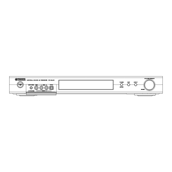
Page 4: Front Panels
RX-SL80 FRONT PANELS RX-SL80 (U, C, R, T, K, A, L models) RX-SL80 (B, G models) RX-SL80 (J model) -
Page 5: Rear Panels
RX-SL80 REAR PANELS RX-SL80 (U, C models) RX-SL80 (R model) RX-SL80 (T model) RX-SL80 (K model) RX-SL80 (A model) RX-SL80(B, G models) -
Page 6: Remote Control Panels
RX-SL80 RX-SL80 (L model) RX-SL80 (J model) REMOTE CONTROL PANELS U, C, R, T, K, A, L, J models B, G models... -
Page 7: Specifications
RX-SL80 SPECIFICATIONS / 参考仕様 Residual Noise / (IHF-A network) Audio Section / 残留ノイズ オーディオ部 FRONT L/R ........... 150 µV or less Minimum RMS Output Power (Power Amp. Section) / Channel Separation / チャンネルセパレーション 定格出力 (パワーアンプ部) (Vol -14 dB, Effect Off) (1 kHz) DVD/CD, etc. - Page 8 消費電力 U, C models ............90 W R, T, K, A, B, G, L models ........90 W J model ............... 130 W "SILENT CINEMA" is a trademark of YAMAHA CORPORATION. Standby Power Consumption (reference data) / 待機時 消費電力(参考値) 「サイレントシネマ/SILENT CINEMA」 はヤマハ株式会社の登録商標で...
- Page 9 RX-SL80 • Set Menu Table / セットメニュー Category MAIN MENU SUB MENU SELECT MENU VALUE [INITIAL] BASIC ROOM: S>M L S, [M], L SET UP SUBWOOFER [YES], NONE SPEAKERS 5 spk 2, 3, 4, [5] >SET CANCEL [SET], CANCEL Check:...
-
Page 10: Internal View
RX-SL80 • The variable range of the parameter (Min/Max/Step) / ) パラメーターの可変範囲(最小/最大/ステップ Unit Pro Logic II Music Parameter Unit DSP LEVEL -6 / +3 / 1 PANORAMA OFF / ON DELAY 1 / 99 / 1 DIMENSIONS -3 / +3 / 1... -
Page 11: Disassembly Procedures
RX-SL80 DISASSEMBLY PROCEDURES / 分解手順 * The description below uses G model as a representative ※ 本項目では、代表としてG modelについて記述します。 model. (Remove parts in the order as numbered.) (番号順に部品を取り外してください。) Disconnect the power cable from the AC outlet. AC電源コンセントから、電源コードを抜いてください。 1. Removal of Top Cover (Fig. 1) 1. - Page 12 RX-SL80 5. Removal of Rear Panel (Fig. 3) 5. リアパネルの外し方 (Fig. 3) a. Remove 1 screw (7) and 3 screws (8). のネジ1本、 のネジ3本を外します。 b. Remove the Rear Panel rearward. b. リアパネルを後方に外します。 c. Remove CB4, CB6, CB10, CB51, CB404 and CB406.
- Page 13 RX-SL80 DIGITAL P.C.B. CB303 – POWER (1) P.C.B. CB5: DIGITAL P.C.B. CB303 – POWER (1) P.C.B. CB5: MFA18400 (18P 400mm) MFA18400 (18P 400mm) DIGITAL P.C.B. CB306 – INPUT (1) P.C.B. CB409: DIGITAL P.C.B. CB306 – INPUT (1) P.C.B. CB409: MFA40400 (40P 400mm) MFA40400 (40P 400mm) DIGITAL P.C.B.
- Page 14 RX-SL80 SELF DIAGNOSIS FUNCTION (DIAG)/ 自己診断機能 (ダイアグ) There are 15 DIAG menu items, each of which has sub- ダイアグメニューは15個あり、そのそれぞれにサブメニューがあ menu items. Listed in the table below are menu items and ります。下表はメニュー一覧です。 sub-menu items. DIAG menu Sub-menu DSP THR 1. YSS MARGIN 2.
- Page 15 RX-SL80 DIAG menu Sub-menu 4. CHANNEL STATUS 2 (5 Byte) 5. CHANNEL STATUS 3 (5 Byte) 6. CHANNEL STATUS 4 (5 Byte) 7. CHANNEL STATUS 5 (4 Byte) 8. BSI 1 (5 Byte) 9. BSI 2 (5 Byte) 10. BSI 3 (5 Byte) 11.
- Page 16 RX-SL80 • Starting DIAG ● ダイアグの起動 Press the “STANDBY/ON” key while simultaneously “INPUT” キーを押しながら “STANDBY/ON” キーを押すと、ダ pressing the “INPUT” key. イアグが起動します。 • Starting DIAG in the protection cancel ● プロテクション解除モードでの起動 mode プロテクションが動作することにより、故障箇所の診断に支障を きたすような場合は、次の方法によりプロテクションを解除した If the protection function works and causes hindrance to 状態でダイアグモードに入ることができます。...
- Page 17 RX-SL80 • Display provided when DIAG started ● ダイアグ起動時の表示 The FL display of the main unit displays the protection 本体のFLディスプレイにプロテクション履歴情報とバージョン function history data and the version (1 alphabet) and the (英1文字) が表示され、数秒後にダイアグメニュー (No.1 DSP DIAG menu [sub-menu (YSS MARGIN) of DIAG menu No.1 THROUGHのサブメニューYSS MARGIN)...
- Page 18 RX-SL80 When there is a history of protection function due to excessive UCD amplifier temperature UCDアンプの異常温度による Version (1 alphabet) プロテクション履歴がある場合 バージョン (英1文字) Voltage display in % 電圧の%表示 原因: UCDアンプの温度が異常。 Cause: The temperature of the UCD amplifier is excessive. 補足: 異常時の電圧の状態を、5Vを500%とした値で%表示し...
- Page 19 RX-SL80 • Operation procedure of DIAG menu and ● ダイアグメニューとサブメニューの操作 SUB-MENU メニュー選択モードへの入り方 ダイアグにはNo.1∼17のメニューがあり、そのそれぞれにサブ Entering Menu Select Mode メニューがあります。 There are 17 MENU items, each of which has some SUB- ダ イ ア グ メ ニ ュ ー ま た は サ ブ メ ニ ュ ー を 選 択 す る と き は 、...
- Page 20 RX-SL80 • Details of DIAG menu ● ダイアグメニュー詳細 With full-bit output specified in some modes, it is possible 一部のモードでフルビット指定することで、各チャンネルのヘッ to execute 0dBFS output without head margin in each ドマージンを廃して0dBFS出力することが可能です。 channel. 1. DSP THR 1. DSP THR Using the sub-menu, it is possible to select margin サブメニューによりMARGIN/Full Bitが選択可能です。...
- Page 21 ANALOG BYPASS RX-SL80 YSS FULL BIT 2. BYPASS ・ サブメニューによりANALOG BYPASS/DSP BYPASSが Using the sub-menu, it is possible to select analog 選択可能です。 bypass output or DSP bypass output. ANALOG BYPASS ANALOG BYPASS INPUT: DVD ANALOG SPEAKER OUTPUT (1 kHz) SUBWOOFER...
- Page 22 RX-SL80 3. RAM THROUGH 3. RAM THROUGH Using the sub-menu, it is possible to select margin output ・ サブメニューによりMARGIN/Full Bitが選択可能です。 or full-bit output. MARGIN (0 dB) MARGIN (0 dB) INPUT: DVD ANALOG SPEAKER OUTPUT (1 kHz) SUBWOOFER Input level Volume...
- Page 23 RX-SL80 4. PRO LOGIC/NEO6 4. PRO LOGIC/NEO6 • Using the sub-menu, it is possible to select Pro Logic I, ・ サブメニューによりPro Logic I/Pro Logic II/Neo:6が選択 Pro Logic II or Neo 6. 可能です。 • Pro Logic I/II: Auto Input Balance Off ・...
- Page 24 RX-SL80 5. SPEAKERS SET 5. SPEAKERS SET The input signal is automatically identified and switched in 入力は信号検出によって、dts → DOLBY DIGITAL → AAC → the priority order of dts → DOLBY DIGITAL → AAC → PCM PCM AUDIO → アナログ (A/D) の優先順で自動判別切り換えさ...
- Page 25 RX-SL80 INPUT: DVD ANALOG SPEAKER OUTPUT (1 kHz) SUBWOOFER Sub-menu Input level Volume FRONT L/R CENTER SUR L/R (50 Hz) FRONT:SML 0dB Both ch, -20 dBm +6.0 dB +9.5 dBm +9.5 dBm +9.5 dBm -2.0 dBm - ∞ CENTER:NONE Both ch, -20 dBm +6.0 dB...
- Page 26 RX-SL80 8. DISPLAY CHECK 8. DISPLAY CHECK This program is used to check the FL display section. The FL表示部のチェックプログラムです。サブメニュー操作により、 display condition varies as shown below according to the 表示状態が以下のように変わります。 sub-menu operation. The signals are processed using 信号処理はEFFECT OFF (ANALOG MAIN BYPASSでL/Rを...
- Page 27 RX-SL80 10. FACTORY PRESET 10. FACTORY PRESET This menu is used to reserve and inhibit initialization of the バックアップ用RAM (音場プログラムのパラメーターやセットメ back-up RAM. The signals are processed using EFFECT ニュー内容等) の初期化を予約/禁止します。 OFF. (The L/R signal is output using ANALOG MAIN 信号処理はEFFECT OFFと同じです (ANALOG MAIN BYPASS BYPASS.)
- Page 28 RX-SL80 11. AD DATA CHECK/FAN TEST 11. AD DATA CHECK/FAN TEST This menu is used to display the A/D conversion value of 本体パネルキー、プロテクションなどを検出している端子のA/D the terminals which detects panel keys of the main unit 変換の値を、サブメニューで%表示します。信号処理は実行前の and protection functions in % using the sub-menu. During 状態を維持します。...
- Page 29 RX-SL80 K0/K1 (Panel key of main unit) K0/K1 (本体パネルキー) A/D of the key fails to function properly when the standard キーのA / D は基準値から外れると、正常な動きをしません。 value is deviated. In this case, check the constant of partial Table 1をご覧になり、各キーの分圧抵抗の定数、ハンダ不良等 pressure resistor, solder condition, etc. Refer to table 1.
- Page 30 RX-SL80 13. IF STATUS (Input function status) 13. IF STATUS Using the sub-menu, the status data is displayed one after サブメニュー操作により、以下のステータス情報を順次16進数で another in the hexadecimal notation. 表示します。信号処理は、本メニュー実行前の状態を維持しま During signal processing, the status before execution of す。 this menu is maintained.
- Page 31 RX-SL80 CS2 (Internal status): (Not used in this model) CS 2 (内部ステータス) : (使用しません) CS1-5: Indicates channel status information of the input CS 1-5: 入力信号のIEC60958チャンネルステータス情報を表示 signal (IEC60958). (Not used in this model) します。(使用しません) BS1-7: Indicates information of the bit stream.
- Page 32 RX-SL80 16. SOFT SW 16. SOFT SW This menu is used to switch the function settings on P.C.B. P.C.B.上の機能設定をソフト的に切り替えて、製品を動作させる through the software so as to activate the product. 機能です。 The protection function follows the P.C.B. settings. When プロテクション機能は、P.C.B.の設定に従います。AC接続または connected to AC or in the maker preset state, the unit is メーカープリセットで、P.C.B.の設定に初期化されます。初期化...
- Page 33 RX-SL80 17. MICROPROCESSOR INFORMATION 17. マイコン情報 The version, checksum and the port specified by the サブメニューは4つあります。 microprocessor are displayed. The signal is processed プログラムのバージョン、チェックサム、マイコンの指定ポート using EFFECT OFF. The checksum is obtained by adding を表示します。 the data at every 8 bits for each program area and 信号はエフェクトOFFです。チェックサムは、プログラムエリア...
-
Page 34: アンプ部調整
RX-SL80 AMP ADJUSTMENT / アンプ部調整 Equipment required 必要なツール • Wire Harness Tie: CB040540 ・ 束線止め:CB040540 (S-72B, L=50mm) (S-72B、L=50mm) • Volt meter ・ 電圧計 Preparation 準備 1. Remove the plastic part (shaded in the figure) of the flat 1. 束線止めのビニール (斜線の部分) を矢印の方向に取り外しま... -
Page 35: Amp Adjustment / Display Data
RX-SL80 DISPLAY DATA ANODE CONNECTION V101 : HNA-16SM08T (WB569700) 13G~1G PATTERN AREA 5-11 PIN CONNECTION PIN NO. 28 27 26 25 24 23 22 21 20 19 18 17 16 15 14 13 12 11 10 9 CONNECTION NP NP NP NP NP NP NP NP NX 15G 14G 13G 12G 11G 10G 9G 8G 7G 6G 5G 4G 3G 2G 1G NP NP F1 F1 PIN NO. -
Page 36: Ic Data
RX-SL80 IC DATA IC302: LC89057W-VF4D-E (DIGITAL P.C.B) Digital Audio Interface Transceiver IC302: LC89057W-VF4D-E (DIGITAL P.C.B) Digital Audio Interface Transceiver Name Function RXOUT Input bi-phase selection data output pin TTL-compatible digital data input pin Coaxial-compatible digital data input pin with built-in amplifier... - Page 37 RX-SL80 IC304: YSS948-V (DIGITAL P.C.B) IC304: YSS948-V (DIGITAL P.C.B) ADAM ADAM Category Name Function Power Supply VDD1 Power supply terminal for terminal block circuit (Typ.3.3V) MEMA15 nMEMCE VDD2 MEMA10 VDD2 nMEMOE MEMA18 nMEMWE STATUS0 MEMA11 STATUS1 MEMA9 STATUS2 MEMA8 STATUS3...
- Page 38 RX-SL80 IC304: YSS948-V (DIGITAL P.C.B) IC304: YSS948-V (DIGITAL P.C.B) ADAM ADAM Category Name Function Category Name Function Power Supply Ground terminal External Memory Interface MEMD6 External memory data input/output terminals 7 to 0 MEMD5 MEMD4 MEMD3 MEMD2 MEMD1 MEMD0 nMEMCE...
- Page 39 RX-SL80 IC306: M30622MHP-199FP (DIGITAL P.C.B) IC306: M30622MHP-199FP (DIGITAL P.C.B) 16 bit µ-COM (CPU) 16 bit µ-COM (CPU) Function No. Name Type Function Name TXD0 SDTR RDS / OSD TxD RXD0 SDRR RDS IC RxD CLK0 SCKR RDS / OSD Clock...
- Page 40 RX-SL80 • Key Input (A-D) Pull-Up Resistance 10 k-ohms IC307: YSS930-SZ (DIGITAL P.C.B) +1.0k +1.5k +3.3k ~0.3 ~1.0 ~1.8 ~2.4 ADKEY0 ENTER INPUT TUNER (94Pin, AN2) VDD2 RAMA11 RAMD9 RAMA12 RAMD8 RAMA13 RAMD7 RAMA14 RAMD6 RAMA15 RAMD5 RAMA16 RAMD4 RAMA17...
- Page 41 RX-SL80 IC307: YSS930-SZ (DIGITAL P.C.B) IC307: YSS930-SZ (DIGITAL P.C.B) Name Function Name Function Digital ground terminal RAMD14 I+/O Data input/output terminal 14 for external memory Terminal for connecting crystal oscillator RAMD15 I+/O Data input/output terminal 15 for external memory Terminal for connecting crystal oscillator (12.288 ~15.0MHz)
- Page 42 RX-SL80 IC312: LC74781JM-9798 (DIGITAL P.C.B) IC312: LC74781JM-9798 (DIGITAL P.C.B) On-screen Display Controller On-screen Display Controller Pin No. Symbol Terminal name Function Ground terminal Connection to GND (Digital system ground terminal) VSS1 Crystal oscillation Terminal to connect the crystal of the crystal oscillator for internal synchronous...
-
Page 43: Block Diagram
RX-SL80 BLOCK DIAGRAM (U, C, R, T, K, A, L, J models) IC402 • See page 63 → SCHEMATIC DIAGRAM MUTE FL/FR (DSP THROUGH) SELECTOR [Front] POWER(5) IC419 TC74H4053AF • See page 61 → • See page 64 → • See page 62 →... - Page 44 RX-SL80 BLOCK DIAGRAM (B, G models) IC402 • See page 63 → SCHEMATIC DIAGRAM MUTE FL/FR (DSP THROUGH) SELECTOR [Front] POWER(5) IC419 TC74H4053AF • See page 61 → • See page 62 → AUDIO SELECTOR SCHEMATIC DIAGRAM 3,13 90Hz SCHEMATIC DIAGRAM...
-
Page 45: Pin Connection Diagram
RX-SL80 PIN CONNECTION DIAGRAM µPC29M33T-E1 NJM78M05DL1A NJM79M05DL1A NJM78M12FA PQ05RA1 PQ012FZ01ZP PQ1CG21H2FZ BA7613N NJM79M12DL1A PQ025EN5MZPH 1: VIN 2: VO 1: VIN 1: VIN 1: IN 1: COM 1: OUTPUT 2: VOUT 1: INPUT 2: VC 3: GND 2: COMMON 3: COM... -
Page 46: Printed Circuit Board
RX-SL80 PRINTED CIRCUIT BOARD (Foil side) Semiconductor Location Ref. No. Location D304 D305 D306 DIGITAL P. C. B. Side A (Lead Free Solder Used) D307 D314 B, G models only IC300 POWER (12) IC302 INPUT (1) IC303 CB303 INPUT (2) - Page 47 RX-SL80 PRINTED CIRCUIT BOARD (Foil side) DIGITAL P. C. B. Side B (Lead Free Solder Used) Semiconductor Location Ref. No. Location D300 D301 D302 D303 IC301 IC308 NOTE) The DIGITAL P.C.B. actually has a four-layer pattern structure (part face pattern, internal pattern 1, internal pattern 2 and solder face pattern) but it is shown as "part face pattern...
- Page 48 RX-SL80 PRINTED CIRCUIT BOARD (Foil side) INPUT (1) P. C. B. Side A INPUT (2) P. C. B. U, C, A, L, R, T, K, J Side A POWER (11) models only CB281 DIGITAL INPUT OPTICAL COAXIAL WRITER VIDEO 1...
- Page 49 RX-SL80 PRINTED CIRCUIT BOARD (Foil side) INPUT (1) P. C. B. Side B (Lead Free Solder Used) INPUT (2) P. C. B. Point r (Pin 29 of IC302) Side B (Lead Free Solder Used) V : 2V/div, H : 40nsec/div DC, 1 : 1 probe •...
- Page 50 RX-SL80 PRINTED CIRCUIT BOARD (Foil side) POWER (1) MAIN (1) P. C. B. Side A (Lead Free Solder Used) MAIN (4) CB691 UCD-B UCDG UCD+B ENABLE UCH2OUT AGND_CH1 UCDG_CH2 UCH1IN UCH1OUT AGND_CH1 UCDG_CH1 UCH2IN AGND_CH2 CLKOUT POWER (3) CB71 UCD UNIT [CH1] SLch...
- Page 51 RX-SL80 PRINTED CIRCUIT BOARD (Foil side) POWER (1) MAIN (4) MAIN (3) P. C. B. Side A (Lead Free Solder Used) CB693 UCD-B UCDG UCD_TH UCD+B ENABLE UCH6OUT DGND UCDG_CH6 UCH5IN UCDG_CH6 AGND_CH5 UCH6IN UCH5OUT AGND_CH6 UCDG_CH5 CLKOUT UCDG_CH5 POWER (3)
- Page 52 RX-SL80 PRINTED CIRCUIT BOARD (Foil side) POWER (1) P. C. B. Side A B, G models only DIGITAL CB303 SGND SGND SGND SGND S5BK SGND RESET PW_DN POW_RY MAIN TRANSFORMER AC_PRT DC_PRT -27V STBY_CTRL +10.6V MAIN TRANSFORMER [ U, C, A, L, R, T, K, J models]...
- Page 53 RX-SL80 PRINTED CIRCUIT BOARD (Foil side) POWER (1) P. C. B. Side B (Lead Free Solder Used) B, G models only Point y CH 1 : Emitter of Q9 POWER (3) P. C. B. Side B (Lead Free Solder Used)
- Page 54 RX-SL80 PRINTED CIRCUIT BOARD (Foil side) Side A POWER (4) P. C. B. DIGITAL CB305 INPUT (1) CB410 VOLUME / SELECT INPUT TUNER POWER (5) P. C. B. Side A POWER (6) P. C. B. POWER (7) P. C. B.
- Page 55 RX-SL80 PRINTED CIRCUIT BOARD (Foil side) POWER (4) P. C. B. Side B (Lead Free solder Used) 49 48 16 17 POWER (5) P. C. B. Side B (Lead Free solder Used) POWER (7) P. C. B. POWER (8) P. C. B.
- Page 56 RX-SL80 PRINTED CIRCUIT BOARD (Foil side) POWER (9) P. C. B. Side A POWER (10) P. C. B. Side A B, G models U, C, R, T, K, A, L, J models INPUT (1) INPUT (1) CB407 CB405 VIDEO • Semiconductor Location...
- Page 57 RX-SL80 PRINTED CIRCUIT BOARD (Foil side) POWER (9) P. C. B. Side B POWER (10) P. C. B. Side B (Lead Free Solder Used) (Lead Free Solder Used) B, G models U, C, R, T, K, A, L, J models •...
-
Page 58: Schematic Diagram
RX-SL80 SCHEMATIC DIAGRAM (INPUT 1/2) DIGITAL INPUT IC551, 552 : TC74HCU04AFEL Hex Inverters * All voltages are measured with a 10M Ω /V DC electronic volt meter. * 電圧は、内部抵抗10MΩの電圧計で測定したものです。 * Components having special characteristics are marked Z and * Z印のある部品は、安全性確保部品を示しています。部品の交換が必要な場合、... - Page 59 RX-SL80 SCHEMATIC DIAGRAM (DIGITAL) Page 63 Page 63 Page 60 Page 62 Page 64 Page 60 Page 61 to POWER(4) to POWER(5) to INPUT(1) to POWER(1) to POWER(12) to INPUT(1) Point q (Pin 29 of IC302) to MAIN V : 2V/div, H : 40nsec/div...
- Page 60 RX-SL80 SCHEMATIC DIAGRAM (INPUT 2/2) Page 59 Page 63 Page 59 Page 64 Page 64 to DIGITAL to POWER (4) to DIGITAL to POWER (10) to POWER (11) IC401: BD3842FS-E2 Point r (Pin 29 of IC302) Function Switch V : 2V/div, H : 40nsec/div...
- Page 61 RX-SL80 SCHEMATIC DIAGRAM (MAIN) Page 62 Page 62 Page 62 Page 62 Page 62 Page 62 IC691~693: NJM2068MD-TE2 to POWER (3) to POWER (1) to POWER (3) to POWER (1) to POWER (3) to POWER (1) Dual OP-Amp. –IN –...
- Page 62 RX-SL80 SCHEMATIC DIAGRAM (POWER 1/3) SURROUND L CENTER FRONT L 11.5 42.2 11.9 42.2 11.9 12.3 12.3 42.3 -41.9 AC 61.7 13.0 13.0 12.3 -28.3 -27.7 -40.5 -40.5 12.8 10.8 12.6 15.5 12.6 AC 13.5 11.4 11.9 12.6 11.4 AC 8.9 15.5...
- Page 63 RX-SL80 SCHEMATIC DIAGRAM (POWER 2/3) FL DISPLAY STANDBY/ON -23.6 -25.7 -23.7 -25.6 -25.7 -27.6 -20.3 -23.8 -25.7 -21.7 -23.7 -27.6 -23.6 -27.8 -23.7 FL DRIVER -23.8 -27.6 -19.8 -23.8 -23.8 -23.7 -23.7 -19.9 -20.0 -20.0 -27.6 -18.1 -25.7 -25.7 -18.0 -25.7...
- Page 64 RX-SL80 SCHEMATIC DIAGRAM (POWER 3/3) Page 59 to DIGITAL 10.8 10.8 10.7 x: NOT USED O: USED / APPLICABLE IC303~304: BA7613N Video Signal Selector 10.8 10.8 MUTE 6dB Amp. 75ohm Driver Logic IC301: BD3842FS-E2 Function Switch LOGIC IC261: TC74HC4051AFEL IC281: LA7108M...
-
Page 65: Parts List
RX-SL80 PARTS LIST ELECTRICAL PARTS WARNING Components having special characteristics are marked s and must be replaced with parts having specifications equal to those originally installed. ● 印のある部分は、 安全確保部品を示しています。 部品の交換が必要な場合、 パーツリス トに記載されている部品を使用してく ださい。 ● 部品価格ランクは、 予告なく変更することがあります。 ABBREVIATIONS IN THIS LIST ARE AS FOLLOWS: C.A.EL.CHP... - Page 66 RX-SL80 P.C.B. DIGITAL & P.C.B. INPUT Schm Ref. PART NO. Description Remarks Markets 部 品 名 Rank WD598600 P.C.B. DIGITAL PCB デジタル WD598700 P.C.B. DIGITAL UCRK PCB デジタル WD598800 P.C.B. DIGITAL PCB デジタル WD598900 P.C.B. DIGITAL PCB デジタル CB301 WC196500 CN 15P TE FMNコネクター CB302 WC196500 CN 15P TE FMNコネクター...
- Page 67 RX-SL80 P.C.B. INPUT Schm Ref. PART NO. Description Remarks Markets 部 品 名 Rank WD598300 P.C.B. INPUT PCB インプット WD598400 P.C.B. INPUT PCB インプット CB401 VB390400 CN.BS.PIN ベースピン CB402 V7825800 CN 8P TE TUC SERIES JUCRTKAL コネクタープラグ CB403 V7825900 CN 9P TE TUC SERIES JUCRTKAL コネクタープラグ...
- Page 68 RX-SL80 P.C.B. INPUT Schm Ref. PART NO. Description Remarks Markets 部 品 名 Rank C471 UM397100 C.EL 10uF ケミコン C472 UR867470 C.EL 47uF ケミコン C473 UR867470 C.EL 47uF ケミコン C476 UA652100 C.MYLAR 100pF マイラーコン C477 UA652100 C.MYLAR 100pF マイラーコン C478 UA652100 C.MYLAR 100pF マイラーコン...
- Page 69 RX-SL80 P.C.B. INPUT Schm Ref. PART NO. Description Remarks Markets 部 品 名 Rank C548 UR819100 C.EL 1000uF 6.3V ケミコン C555 UR867220 C.EL 22uF ケミコン C562 UR838100 C.EL 100uF ケミコン D401 VT332900 DIODE 1SS355 ダイオード s D402 VU995500 DIODE.ZENR MA8100-H 10.3V ツェナーダイオード...
- Page 70 RX-SL80 P.C.B. INPUT & P.C.B. MAIN Schm Ref. PART NO. Description Remarks Markets 部 品 名 Rank Q410 VV655000 TR.DGT DTA114EKA デジタルトランジスタ 01 Q411 WC756200 TR 5938A A,B トランジスタ 2SC Q412 WC756200 TR 5938A A,B トランジスタ 2SC Q413 WC756200 TR 5938A A,B トランジスタ 2SC Q415...
- Page 71 RX-SL80 P.C.B. MAIN Schm Ref. PART NO. Description Remarks Markets 部 品 名 Rank CB694 WB832600 CN 6P TE FMNコネクター CB695 VF982300 CN.BS.PIN FFCコネクター C601 UR838100 C.EL 100uF ケミコン C602 UR857100 C.EL 10uF ケミコン C603 UR857100 C.EL 10uF ケミコン C604 UR857100 C.EL 10uF ケミコン...
- Page 72 RX-SL80 P.C.B. MAIN & P.C.B. POWER Schm Ref. PART NO. Description Remarks Markets 部 品 名 Rank Q666 VV655000 TR.DGT DTA114EKA デジタルトランジスタ 01 Q667 VV655400 TR.DGT DTC114EKA デジタルトランジスタ 01 Q668 VV655400 TR.DGT DTC114EKA デジタルトランジスタ 01 Q691 VV556500 TR 2SA1037K Q,R,S トランジスタ Q692...
- Page 73 RX-SL80 P.C.B. POWER Schm Ref. PART NO. Description Remarks Markets 部 品 名 Rank CB303 V7414100 CN 15P SE FMNコネクター CB304 WB497100 CN 21P YKF41-5044 RGBコネクタ UR837100 C.EL 10uF ケミコン UR837100 C.EL 10uF ケミコン WB165500 C.EL 0.33F 5.5V ゴールドキャパシタ UR819100 C.EL 1000uF 6.3V...
- Page 74 RX-SL80 P.C.B. POWER Schm Ref. PART NO. Description Remarks Markets 部 品 名 Rank C305 UR837100 C.EL 10uF ケミコン C306 UR837100 C.EL 10uF ケミコン C307 UR837100 C.EL 10uF ケミコン C308 UR837100 C.EL 10uF ケミコン C309 UR837100 C.EL 10uF ケミコン C310 UR837100 C.EL 10uF ケミコン...
- Page 75 RX-SL80 P.C.B. POWER Schm Ref. PART NO. Description Remarks Markets 部 品 名 Rank JK161 WB071300 JACK.MNI LGS6516-0100 ミニジャック PJ161 V6753000 JACK.PIN ピンジャック PJ201 V2069700 JACK.PIN JUCRTKAL ピンジャック PJ221 VM725900 JACK.PIN JUCRTKAL ピンジャック PJ222 V7189700 JACK.PIN JUCRTKAL ピンジャック PJ241 V7189700 JACK.PIN ピンジャック...
- Page 76 RX-SL80 P.C.B. POWER Schm Ref. PART NO. Description Remarks Markets 部 品 名 Rank R290 HV753100 R.CAR.FP 1Ω 1/4W JUCRTKAL 不燃化カーボン抵抗 s RY1 V6017400 RELAY DC SDT-S-112LMR2 リレー 12V ST241 V4040500 SCR.TERM スクリュー/ターミナル 01 SW51 VZ075500 SW.SLIDE SL14-22AM5F スライドSW SW101 WD872500 VR XRE0122PVB20FINB1 12形エンコーダー...
- Page 77 RX-SL80 Chip Parts Chip Parts Schm Schm Ref. PART NO. Description Remarks Markets 部 品 名 Rank Ref. PART NO. Description Remarks Markets 部 品 名 Rank UF028100 C.EL.CHP 100uF チップケミコン RD356330 R.CHP 3.3KΩ 1/16W チップ抵抗 UF037100 C.EL.CHP 10uF チップケミコン RD356390 R.CHP 3.9KΩ 1/16W チップ抵抗...
- Page 78 RX-SL80 EXPLODED VIEW MECHANICAL PARTS Schm B, G models Ref. PART NO. Description Remarks Markets 部 品 名 Rank MFA10100 FLEXIBLE FLAT CABLE 10P 100mm P=1.0 カード電線 MF105100 FLEXIBLE FLAT CABLE 5P 100mm P=1.25 カード電線 C&C 01 WD369000 FRONT PANEL フロントパネル WD368800 FRONT PANEL UCRTKAL フロントパネル ...
- Page 79 RX-SL80 Schm Ref. PART NO. Description Remarks Markets 部 品 名 Rank WC272400 DC FAN MOTOR DC D04R-24TM05(EX) DCファンモーター MFA40060 FLEXIBLE FLAT CABLE 40P 60mm P=1.0 カード電線 MFA15120 FLEXIBLE FLAT CABLE 15P 120mm P=1.0 カード電線 MFA18120 FLEXIBLE FLAT CABLE 18P 120mm P=1.0 カード電線 ...
-
Page 80: Remote Control
RX-SL80 REMOTE CONTROL P0D2 P1A2 3.0V 47µF P0D3 P0D1 P1B0/INT P0D0 P0E0 P0C3 P0E1 P0C2 2Ω (1/4W) P0E2 P0C1 MIE554A2 P0E3 P0C0 AV STANDBY/ON SKIP (–) DOWN VOLUME (+) TV MUTE P0B3 VIDEO 2 TV STANDBY/ON SEARCH (+) 27Ω 2SD1781K-Q... - Page 81 RX-SL80 Key Layout CODE Function DVD/CD VIDEO1 DTV/CBL TUNER VIDEO2 STANDBY/ON 7A-1F SLEEP 7A-57 7A-88 7C-94 – – – 7A-E5 – 7A-89 7C-95 – – – 7A-E6 – 7A-8A 7C-96 – – – 7A-E7 – 7A-8B 7C-97 – – –...
- Page 82 RX-SL80...
Need help?
Do you have a question about the RX-SL80 and is the answer not in the manual?
Questions and answers