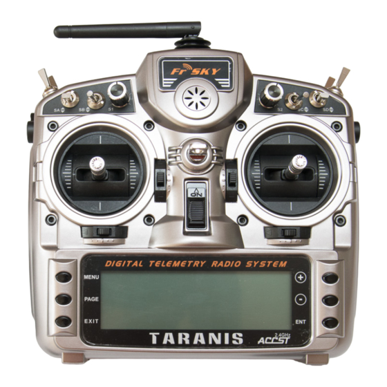
Summary of Contents for FrSky E-Soar
- Page 1 E-Soar for FrSky Taranis and Horus Version 2.0 Setup Guide Mike Shellim 8 Feb 2017 Copyright © Michael Shellim...
-
Page 2: Table Of Contents
Contents 1 Introduction ....................3 1.1 Package contents ..................3 1.2 Requirements ..................3 1.3 Nomenclature ..................3 1.4 Flight modes .................... 3 1.5 Mixers ...................... 4 1.6 Stick and switch assignments ..............4 1.7 Channel assignments ................4 2 Operational Overview ..................5 3 Motor operation ..................... -
Page 3: Introduction
1 Introduction E-Soar is a full-feature setup for electric-powered gliders with 4 servos in the wing. It contains all the mixing needed for F5J competition, yet is easy to configure and operate. Key mixers may be adjusted in flight and an integrated flight timer is included. Special attention has been paid to motor safety with a simple and secure motor arming system. -
Page 4: Mixers
1.5 Mixers The table below shows which mixers are active in each flight mode. Mix adjusters are in brackets. Ail→ Ail→ Motor Spoiler Spoiler Camber Diff Flight Flap (Crow) comp diff mode Power Y(RudTrm) Landing Y(Thr trm) Y(RudTrm) Cruise Y(RudTrm) Thermal Y (RS) Y(RudTrm) -
Page 5: Operational Overview
Operational Overview Flight trims Aileron trim is shared across all flight modes Elevator trim is independent for each flight mode Rudder and throttle trims are repurposed for other functions (see below) Camber mix Camber of flaps and ailerons is adjustable via RS (Thermal mode only) Spoiler compensation (spoiler to elevator) ... -
Page 6: Disarming The Motor
3.3 Disarming the motor To disarm the motor motor, pull SH until you hear the ‘motor disabled’ alert. 3.4 Motor safety To minimise the risk window, arm the motor immediately before launch, and disarm straight after landing. The arming system will not protect against loss of signal. It’s therefore imperative to set the failsafe on your transmitter, so the motor is commanded to ‘off’... -
Page 7: Preparation
6.1 Preparation In this section you’ll load prepare the transmitter, and familiarise with the basic operation and sounds. 6.1.1 Transfer files to transmitter In this step you’ll upload the setup to your transmitter’s EEPROM. Establish communication with your PC □ Taranis: Switch on the transmitter whilst pressing horizontal trim levers towards the centre Horus: Switch on the transmitter □... -
Page 8: Calibrating The Servos
6.2 Calibrating the servos In this section you’ll calibrate the servos. The goals are: Maximise control surface movements Achieve a left/right symmetry regardless of linkage differences Linearise responses. All the adjustments in this section are made in CAL mode. Note: correct calibration is essential for diff to work correctly, and for precise tracking of flaps with ailerons. - Page 9 Channel Calibration procedure Start by calibrating left flap (CH4). The goal is (a) set the end points, and CH 4 – Lt Flap (b) linearise the response. Note: the flap neutral will be adjusted later. 1. Enter CAL mode 2. Set switch SA to middle position 3.
-
Page 10: Backup Your Eeprom
Channel Calibration procedure X-Tail X-tail version only - Calibrate elevator 1. Enter CAL mode CH 5 – Ele 2. In the menu, highlight CH5 OUTPUTS 3. Skip to curve field ‘CV15’, press {long } to open curve editor ENTER 4. Ele stick to centre, adjust point 2 for correct neutral 5. -
Page 11: Configuring Inputs And Mixing
Configuring inputs and mixing In the last section, you’ll set the control movements and mixing. Control / mix Adjustment point Adjustment procedure INPUTSAil Set the default rate for ailerons. Aileron rate 1. Open the Inputs menu 2. Scroll down to [I]Ail 3. - Page 12 Control / mix Adjustment point Adjustment procedure GVARSGV2(‘CmFlap’) Sets the downward flap movement due to spoiler. SpoilerFlap 1. Enable Landing mode 2. Open menu GLOBALVARS 3. Skip to cell GV2/FM3 4. Move throttle stick back (full spoiler) 5. Adjust value for required down-flap movement GVARSGV1(‘CmAil’) Camber can be adjusted in Thermal mode using lever RS.
-
Page 13: Motor Safety Check
Control / mix Adjustment point Adjustment procedure GVARSGV3(‘Comp’) Spoiler compensation is used to counteract pitch changes as SpoilerEle spoiler/crow is applied. It can be fine tuned in flight using compensation the throttle trim. Trim fully back = zero compensation ... -
Page 14: Summary Of In-Flight Adjusters
Summary of in-flight adjusters Target Adjuster Flight mode Notes Aileron Diff Rudder trim [Any] Diff is stored per flight mode Default range is 0 - 70% Trim centre corresponds to 35% diff SpoilerEle compensation Throttle trim Landing Adjust compensation with full spoiler deployed Trim fully back →... -
Page 15: Reversing Flap Lever
10.4 Reversing flap lever To reverse the direction of the flap lever 1. Open the M menu IXERS 2. Skip to CH 20 (‘Flap’) 3. Change weight from +25 to -25 10.5 Rates There is no dedicated ‘rates’ or ‘expo’ menu in OpenTx. Instead, you add extra lines in the menu. -
Page 16: Adjusting Spoiler Deadband
10.7 Adjusting spoiler deadband The response of the spoiler control incorporates some deadband at the idle end to help prevent accidental deployment. The default value should be fine for most pilots; however it can be adjusted as follows: 1. Go to Curves menu 2.


Need help?
Do you have a question about the E-Soar and is the answer not in the manual?
Questions and answers