Table of Contents
Advertisement
Quick Links
-
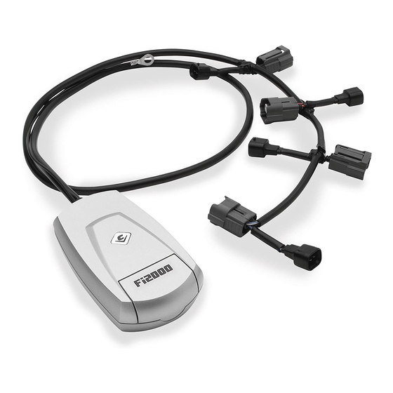
Items Supplied >
1 – Fi2000R Fuel Injection Module
2 – Zip Ties, (1): 3/32" x 6"; & (1): 3/16" x 8"
3 – Velcro Strip
Instruction Manual >
Read all instructions carefully and completely before installing your new Fi2000R module.
It is recommended that a qualified mechanic or technician install this product.
Before installing the Fi2000R it is recommended that the gas tank be low on fuel.
1. Remove both seats; remove the fuel tank console. Next, remove the fuel tank by removing the
bolts and lifting the tank enough to gain access to the white wire connectors and dry brake fuel
line. Unplug the wire connectors by pressing the tabs inwards. Disconnect the dry brake fuel line
by depressing the two gray tabs.
2. Loosen the clamp on the air intake boot just enough to release the boot from the throttle body
assembly to lift upwards. The boot does not have to be fully removed.
3. Temporarily position the FI2000R module by the battery, and route the wire harness forward
underneath the starter solenoid cable and into the notch in plastic cover, (Fig.1.) Continue routing
the harness under the frame at the rear of the fuel tank, and continue it up past the left side of the
throttle body assembly.
4. Push the air intake boot to the right to gain access to the front fuel injector. Release the black
injector connector by squeezing the two side tabs inward and pulling it away at the same time,
(Fig. 2.) Now connect the forward Fi2000R matching connector to the injector and then connect
the original connector to the corresponding Fi2000R connector. Replace the air boot and tighten
the clamp.
5. Locate the rear injector on the throttle body housing and repeat the procedure in Step 4. When
finished, make sure the wire harness does not foul any throttle cable linkage. Zip tie the harness
as indicated in, (Fig. 3.) Reinstall the fuel tank by reconnecting the white wire connectors and dry
brake fuel line to the fuel tank.
6. Connect the Fi2000R ground wire (black), to the negative post of the battery and attach the
Fi2000R module to the top of the plastic panel with the supplied Velcro, (Fig. 1.) Before
reinstalling the seats verify all connections are made properly.
7. Remove the door from the Fi2000R module to expose the LED's. Verify the wire connections by
(1) turning on the ignition while watching the 3 LED's. They will all light up for a few seconds, then
go off. This is correct. If you don't see lights, make sure the side stand is up, bike is in neutral,
clutch is in and handle bar engine switch is set to run. If you still have no lights, re-check that all
connectors are fully engaged and the ground wire is connected correctly.--(Continued next page)
* Cobra recommends you always wear a helmet while riding. Please never operate your motorcycle while under
the influence of alcohol and/or drugs. Enjoy the new look of your motorcycle and please ride safely.
DOCUMENT NO. 0017
REV. A
11/08
23801 E. La Palma Ave., Yorba Linda, Ca 92887 Ph. 714.692.8180 Fax. 714.692.5016
Application(s) >
Suzuki Boulevard C50 05-08
Suzuki Boulevard M50 05-08
1
92-1826
www.fi2000r.com
Page 1 of 4
Advertisement
Table of Contents

Related Manuals for Cobra Fi2000R


Summary of Contents for Cobra Fi2000R
- Page 1 6. Connect the Fi2000R ground wire (black), to the negative post of the battery and attach the Fi2000R module to the top of the plastic panel with the supplied Velcro, (Fig. 1.) Before reinstalling the seats verify all connections are made properly.
- Page 2 ADVANCED TUNING The Fi2000R has the ability to efficiently tune the EFI system on your motorcycle for slip-on or full exhaust systems. It comes pre-set from the factory for popular brand name slip-on mufflers. Both dyno testing and on-road exhaust gas analysis have been used to develop the best base settings for drivability and power.
- Page 3 FIGURE 1 Air intake boot Moved to side Fi2000R Harness forward Connector Throttle linkage FIGURE 2 Rear Fi2000R Rearward Harness Zip tied Connector to intake boot clamp Frame Rail FIGURE 3 (Fuel tank removed for access to injector connector locations) DOCUMENT NO.
- Page 4 23801 E. La Palma Ave., Yorba Linda, Ca 92887 Ph. 714.692.8180 Fax. 714.692.5016 www.fi2000r.com Instruction Manual > Page 4 of 4 92-1826 Default Pot Settings: Green Yellow FIGURE 4 11/08...
Need help?
Do you have a question about the Fi2000R and is the answer not in the manual?
Questions and answers