Advertisement
Quick Links
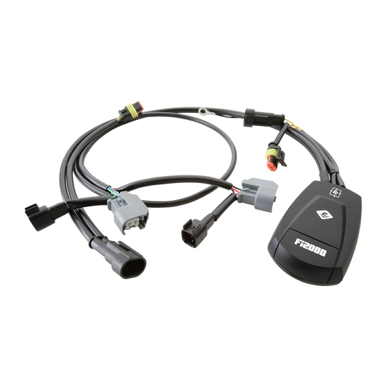
Items Supplied >
1 – POWRPRO Fuel Injection Module
1 – Velcro Strip
1 – Ziptie 8"
1 – Ziptie 14"
Instruction Manual >
Read all instructions carefully and completely before installing your new POWRPRO module. It is
recommended that a qualified mechanic or technician install this product.
1. It is recommended to have the motorcycle positioned on the kickstand with the handlebars at a forty-five degree
angle to the left to aid in accessing components for Powrpro module installation. Remove both left and right
side saddlebags, being careful not to scratch chrome or paint.
2. Remove right side cover and seat to expose engine ECU and oxygen sensor connectors.
3. Loosen and remove the bolt securing the instrument bezel to the rear of the fuel tank. Remove the plastic
shroud at rear of fuel tank, partially covering fuel tank bolts, see Figure 1. Remove the two bolts securing rear
of fuel tank. At the front of the fuel tank remove the rubber covers which are installed on the fuel tank's front
bolts. Loosen the bolts only 1-2 turns, do not remove.
4. Be sure handlebars are at a forty-five degree angle to the left, to prevent instrument bezel from making contact
with ignition lock. Locate a small piece of wood or plastic approx. 2 –3" tall and raise the rear of the fuel tank up
and secure in place with the block, this will allow access to the fuel injector connectors.
5. Place the Powrpro case and harness on right side of the of the motorcycle between the large wire harness and
ABS control block, under the right side panel area, See Figure 2. Route the main fuel injector harness and
ground wire under the right frame rail. Place the fuel injector harness between the frame rail and existing wire
loom sheath as it goes under the rear of the fuel tank. Route connectors up the main frame rail under the fuel
tank to the fuel injectors between the cylinder heads.
6. Disconnect the stock front female injector connector and mate a pair of the Powrpro connectors to the front
injector by installing the Powrpro female connector on to the front injector and stock front female connector to
Powrpro male connector. See Figure 3.
7. Mate the other pair of connectors to the rear injector in the same manner as the front injector, See Figure 3.
8. Now locate the oxygen sensor connectors along the right rear frame rail where the right side cover was
removed. Route the Powrpro oxygen sensor harnesses to this area. Be sure to route them between the large
wire harness and ABS control block. Unplug the light tan set of stock connectors and mate the corresponding
male and female Powrpro connectors to them. Repeat for black set of oxygen sensor connectors. Make sure all
connectors seat firmly, see Figure 4.
9. Attach the ground wire from the Powrpro to the negative battery terminal. Velcro the Powrpro case to the side of
the ABS control block, see Figure 2.
10. Secure the oxygen sensor connectors to the frame with the longer supplied ziptie, see Figure 4. Use the shorter
supplied ziptie to secure the fuel injector harness to the existing wire loom.
11. Remove the block elevating the fuel tank and lower the tank back into place, be sure the injector harness does
not get pinched between the tank and top frame rail.
* Cobra
recommends you always wear a helmet while riding. Please never operate your motorcycle while under
®
the influence of alcohol and/or drugs. Enjoy the new lo ok of your motorcycle and please ride safely.
DOCUMENT NO. 0017
REV. A
11/11
23801 E. La Palma Ave., Yorba Linda, Ca 92887 Ph. 714.692.8180, Fax. 714.692.5016
®
Application(s) >
HARLEY DRESSER
692-1615AT
1
www.fi2000r.com
2010-2013
Page 1 of 3
Advertisement

Subscribe to Our Youtube Channel
Related Manuals for Cobra Fi2000


Summary of Contents for Cobra Fi2000
- Page 1 11. Remove the block elevating the fuel tank and lower the tank back into place, be sure the injector harness does not get pinched between the tank and top frame rail. * Cobra recommends you always wear a helmet while riding. Please never operate your motorcycle while under ®...
- Page 2 23801 E. La Palma Ave., Yorba Linda, Ca 92887 Ph. 714.692.8180, Fax. 714.692.5016 ® www.fi2000r.com Instruction Manual > Page 2 of 3 692-1615AT 12. Verify the wire connections; turn on the ignition and watch the C over V LED logo, confirm that the LED blinks several times then turns off.
- Page 3 FRAME RAIL WITH LARGE ZIPTIE FIGURE 4 NOTE: For California riders we offer Air Resources Board approved Fi2000R ARB units. (ARB E.O. No. D-633-1). All other Fi2000 models are not legal for street use in California. DOCUMENT NO. 0018 REV. A 11/11...
Need help?
Do you have a question about the Fi2000 and is the answer not in the manual?
Questions and answers