Table of Contents
Advertisement
Quick Links
Cisco SNS-3400 Series Appliance Hardware Installation Guide
First Published: 2016-11-23
Last Modified: 2016-11-23
Americas Headquarters
Cisco Systems, Inc.
170 West Tasman Drive
San Jose, CA 95134-1706
USA
http://www.cisco.com
Tel: 408 526-4000
800 553-NETS (6387)
Fax: 408 527-0883
Text Part Number:
Advertisement
Table of Contents

Related Manuals for Cisco SNS 3415


Summary of Contents for Cisco SNS 3415
- Page 1 Cisco SNS-3400 Series Appliance Hardware Installation Guide First Published: 2016-11-23 Last Modified: 2016-11-23 Americas Headquarters Cisco Systems, Inc. 170 West Tasman Drive San Jose, CA 95134-1706 http://www.cisco.com Tel: 408 526-4000 800 553-NETS (6387) Fax: 408 527-0883 Text Part Number:...
- Page 2 © Cisco Systems, Inc. All rights reserved.
-
Page 3: Table Of Contents
Environmental Specifications Power Specifications 650-Watt Power Supply Install the Cisco SNS 3415 and Cisco SNS 3495 Hardware Appliances C H A P T E R 3 Install the Cisco SNS 3415 and Cisco SNS 3495 Hardware Appliances Install the Cisco SNS 3415 or 3495 Appliance in a Rack... - Page 4 Connect the Console Connect the Keyboard and Video Monitor Cable Management Connect and Power On the Cisco SNS 3415 or 3495 Appliance Connect and Power On the Server (Standalone Mode) NIC Modes and NIC Redundancy Settings System BIOS and CIMC Firmware...
-
Page 5: Cisco Sns 3400 Series Appliance Overview
Intel Xeon processor E5-2600 product family, which delivers significant performance and efficiency gains. In addition, the Cisco SNS 3415 Cisco SNS 3495 server offers up to 256 GB of RAM, 8 drives, and 2 x 1 GbE lights-out management (LOM) ports that deliver outstanding levels of density and performance in a compact package. -
Page 6: Led Indicators On Cisco Sns-3415 And 3495 Appliances
Server Specifications, on page LED Indicators on Cisco SNS-3415 and 3495 Appliances This section describes the front- and rear-panel controls, ports, and LED indicators on the Cisco SNS 3415 or Cisco SNS 3495 appliances. • Cisco SNS-3415 or 3495 Appliance Front Panel View, on page 3 •... -
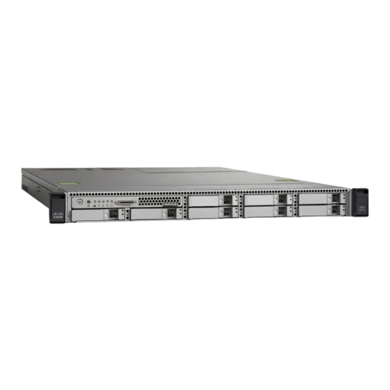
Page 7: Cisco Sns-3415 Or 3495 Appliance Front Panel View
Temperature status LED Drives (up to eight hot-swappable 2-5-inch drives) The following table describes the LEDs located on the front panel of the Cisco SNS-3415 or Cisco SNS-3495 appliance. Front Panel LED Names State Power button/Power status LED •... - Page 8 Cisco SNS 3400 Series Appliance Overview Cisco SNS-3415 or 3495 Appliance Front Panel View Front Panel LED Names State Identification • Off—The identification LED is not in use. • Blue—The identification LED is activated. System status • Green—The server is running in normal operating condition.
- Page 9 Cisco SNS 3400 Series Appliance Overview Cisco SNS-3415 or 3495 Appliance Front Panel View Front Panel LED Names State Power supply status • Green—All power supplies are operating normally. • Amber, steady—One or more power supplies are in a degraded operational state.
-
Page 10: Cisco Sns 3415 Or Sns 3495 Appliance Back Panel View
1-GB Ethernet port 2 (GigE1) 1-GB Ethernet port 4 (GigE3) USB Ports VGA video connector Rear identification button The following table describes the LEDs located on the back panel of the Cisco SNS-3415 or Cisco SNS-3495 appliance. Cisco SNS-3400 Series Appliance Hardware Installation Guide... - Page 11 Cisco SNS 3400 Series Appliance Overview Cisco SNS 3415 or SNS 3495 Appliance Back Panel View LED Name State Power supply fault • Off—The power supply is operating normally. • Amber, blinking—An event warning threshold has been reached, but the power supply continues to operate.
-
Page 12: Internal Diagnostic Leds
Power must be connected to the server for these LEDs to be operational. Note The following figure shows the locations of these internal LEDs in Cisco SNS-3415 or Cisco SNS-3495 appliance. The following table describes the callouts in the above figure. -
Page 13: Regulatory Compliance
Cisco SNS 3400 Series Appliance Overview Regulatory Compliance The following table describes the internal diagnostic LEDs located inside the Cisco SNS-3400 series appliance. LED Name State Internal diagnostic LEDs (all) • Off—Component is functioning normally. • Amber—Component has failed. Regulatory Compliance... - Page 14 Cisco SNS 3400 Series Appliance Overview Regulatory Compliance Cisco SNS-3400 Series Appliance Hardware Installation Guide...
-
Page 15: Before You Begin
C H A P T E R Before You Begin This section provides information on how you can prepare your site for safely installing the Cisco SNS-3415 or Cisco SNS-3495 appliance. • Safety Guidelines, page 11 • Unpack and Inspect the Server, page 12 •... -
Page 16: Unpack And Inspect The Server
16. If available, you can use an uninterruptible power supply (UPS) to protect against power failures. Caution Avoid UPS types that use ferroresonant technology. These UPS types can become unstable with systems such as the Cisco UCS, which can have substantial current draw fluctuations from fluctuating data traffic patterns. Unpack and Inspect the Server... -
Page 17: Prepare For Server Installation
• Effect of damage on the installation Figure 3: Shipping Box Contents Prepare for Server Installation • Installation Guidelines, on page 14 • Rack Requirements, on page 15 • Equipment Requirements, on page 15 Cisco SNS-3400 Series Appliance Hardware Installation Guide... -
Page 18: Installation Guidelines
Caution Avoid UPS types that use ferroresonant technology. These UPS types can become unstable with systems such as the Cisco UCS, which can have substantial current draw fluctuations from fluctuating data traffic patterns. When you are installing a server, use the following guidelines •... -
Page 19: Rack Requirements
• The minimum vertical rack space per server must be one RU, equal to 1.75 in. (44.45 mm). Equipment Requirements The slide rails supplied by Cisco Systems for this server do not require tools for installation. The inner rails (mounting brackets) are pre-attached to the sides of the server. -
Page 20: Environmental Specifications
You can get more specific power information for your exact server configuration by using the Cisco UCS Power Calculator. Do not mix power supply types in the server. Both power supplies must be either 650W. Note Cisco SNS-3400 Series Appliance Hardware Installation Guide... - Page 21 Before You Begin Power Specifications Table 4: Cisco SNS-3400 Series Server 650-Watt Power Supply Specifications Description Specification AC input voltage range 90 to 264 VAC (self-ranging, 180 to 264 VAC nominal) AC input frequency Range: 47 to 63 Hz (single phase, 50 to 60Hz nominal) AC line input current (steady state) 7.6 A peak at 100 VAC 3.65 A peak at 208 VAC...
- Page 22 Before You Begin Power Specifications Cisco SNS-3400 Series Appliance Hardware Installation Guide...
-
Page 23: Install The Cisco Sns 3415 And Cisco Sns 3495 Hardware Appliances
Cisco Integrated Management Controller, page 30 Install the Cisco SNS 3415 and Cisco SNS 3495 Hardware Appliances This section describes how to install your Cisco SNS 3415 or 3495 appliance and connect it to the network. It contains: • Install the Cisco SNS 3415 or 3495 Appliance in a Rack, on page 20 •... -
Page 24: Install The Cisco Sns 3415 Or 3495 Appliance In A Rack
Statement 1017 Install the Cisco SNS 3415 or 3495 Appliance in a Rack This section describes how to install the Cisco SNS 3415 or Cisco SNS 3495 appliance in a rack. Install the Side Rails To prevent bodily injury when mounting or servicing this unit in a rack, you must take special precautions Warning to ensure that the system remains stable. - Page 25 Install the Cisco SNS 3415 and Cisco SNS 3495 Hardware Appliances Install the Side Rails c) Release the clip marked “PULL” to lock the securing latch in the open position. Figure 4: Front Securing Latch Clip marked “PULL” on rear of assembly...
- Page 26 Install the Cisco SNS 3415 and Cisco SNS 3495 Hardware Appliances Install the Side Rails Note The mounting pegs that protrude through the rack-post holes are designed to fit round or square holes, or smaller #10-32 round holes when the mounting peg is compressed. If your rack has #10-32 rack-post holes, align the mounting pegs with the holes and then compress the spring-loaded pegs to expose the #10-32 inner peg.
-
Page 27: Install The Cable Management Arm (Optional)
Install the Cisco SNS 3415 and Cisco SNS 3495 Hardware Appliances Install the Cable Management Arm (Optional) c) Push in the plastic release clip on each inner rail (labelled PUSH), and then continue pushing the server into the rack until its front latches engage the rack posts. -
Page 28: Connect Cables
Outer CMA arm attachment clip Flange on rear of outer right slide rail Connect Cables This section describes how to connect your Cisco SNS-3415 or Cisco SNS-3495 appliance to the network and the appliance console. • Connect the Network Interface, on page 24 •... -
Page 29: Connect The Console
To connect an ASCII terminal to the console port, use a DB-9 female to DB-25 male straight-through cable with a DB-25 female to DB-25 female gender changer. To connect a terminal or a PC running terminal-emulation software to the console port on the Cisco SNS-3415 or Cisco SNS-3495 appliance: Step 1 Connect the terminal using a straight-through cable to the console port. -
Page 30: Cable Management
The Cisco SNS-3415 or Cisco SNS-3495 appliance does not provide support for a mouse. The Cisco SNS-3415 or Cisco SNS-3495 provides USB ports on the rear of the appliance that can be used to connect a keyboard and video monitor. -
Page 31: Connect And Power On The Server (Standalone Mode)
Management Interface (CIMC). If you want to use the 1-Gb Ethernet dedicated management port, or a port on a Cisco UCS P81E Virtual Interface Card (VIC) to access the CIMC, you must first connect to the server and change the NIC mode as described in Step 3 of the following procedure. In that step, you can also change the NIC redundancy and set static IP settings. -
Page 32: Nic Modes And Nic Redundancy Settings
LOM and Cisco Card interfaces are both enabled. In this mode, DHCP replies are returned to both the shared LOM ports and the Cisco card ports. If the system determines that the Cisco card connection is not getting its IP address from a Cisco UCS Manager system because the server is in standalone mode, further DHCP requests from the Cisco card are disabled. -
Page 33: System Bios And Cimc Firmware
• You can upgrade the BIOS using the EFI interface, or upgrade from a Windows or Linux platform. See the Cisco UCS C-Series Rack-Mount Server BIOS Upgrade Guide. • You can upgrade the CIMC and BIOS firmware by using the CIMC GUI interface. See the Cisco UCS C-Series Rack-Mount Server Configuration Guide. -
Page 34: Access The System Bios
Esc. Cisco Integrated Management Controller You can monitor the server inventory, health, and system event logs by using the built-in Cisco Integrated Management Controller (CIMC) GUI or CLI interfaces. See the user documentation for your firmware release at the following URL: http://www.cisco.com/c/en/us/support/servers-unified-computing/ucs-c-series-integrated-management-controller/... - Page 35 Install the Cisco SNS 3415 and Cisco SNS 3495 Hardware Appliances Setup CIMC Configuration Utility Step 3 During bootup, press F8 when prompted to open the BIOS CIMC Configuration Utility. The following screen appears. Cisco SNS-3400 Series Appliance Hardware Installation Guide...
- Page 36 • Shared LOM (default)—The two 1-Gb Ethernet ports are used to access the CIMC. This is the factory default setting, along with Active-active NIC redundancy and DHCP enabled. • Cisco Card—The ports on an installed Cisco UCS P81E VIC are used to access the CIMC. You must select a NIC redundancy and IP setting.
Need help?
Do you have a question about the SNS 3415 and is the answer not in the manual?
Questions and answers