
Subscribe to Our Youtube Channel
Summary of Contents for Vingtor CTB-100V
- Page 1 CTB-100V Command Talk Back & Public Address System INSTALLATION & USER MANUAL A100K10864...
-
Page 2: Table Of Contents
Installation & User Manual System CTB-100V Table of Contents 1. GENERAL..................................1 Purpose of this manual ................................1 1.2. Related documents ................................1 1.3. Publication log ..................................1 1.4. Requirements ..................................1 1. SYSTEM OVERVIEW..............................2 2.1. Introduction ................................ 2 2.2. Features ....................................2 2.2. -
Page 3: Purpose Of This Manual
Purpose of this manual This manual supplies an engineer with the information required to install and commissioning a CTB-100V system and the end-user with all necessary instructions for operating the CTB_100V system. Refer to Service Manual for maintenance and repair. -
Page 4: General
Installation & User Manual System CTB-100V 4.3.1 Operation from STB-1 ...............................35 4.3.2 Operation from STB-2 ...............................35 4.3.3 Operation from STB-3 ...............................36 4.3.4 Operation from STB-5 ...............................37 4.3.5 Operation from STB-5GN ..............................38 4.3.6 Operation from HE-112M / HE-112MT ..........................38 4.3.7 Operation from VH-10M / VH-10M-T ..........................39 4.3.8... -
Page 5: System Overview
2.1. Introduction The Command Talk Back System CTB-100V is specially designed for important communication for use in rough marine environment. Available in 10 and 20 line version. The CTB system consist of a central unit CU-100 or CU-200 with up to 4 operation panels for use on bridge console, bridge wings, engine control room etc. -
Page 6: Optional Equipment
Installation & User Manual System CTB-100V 2.2. Optional Equipment See chapter 6 for further details and datasheet Central units, operator panels and microphones. CU-100 Central unit 10 line 24V DC CU-200 Central unit 20 line 24V DC CTB-10 Operation panel, 10 lines... -
Page 7: Functions & User Facilities
Installation & User Manual System CTB-100V 2.4. Functions & User Facilities. 2.4.1 General The CTB-100 system consist of 1 central unit CU-100 or Cu-200, 1 to 4 operation panels, 1 to 20 substations or loudspeakers and one 100V power amplifier. On system with more than 1 operation panel, each panel take one substation line. -
Page 8: All Call
Installation & User Manual System CTB-100V 2.4.5 All call All call message can be distributed from any operation panel to all substations and other operation panels. All call message will also activate Public Address System if connected. Indicated with steady green LED in the «ALL» push button. -
Page 9: Parallel Communication
Installation & User Manual System CTB-100V 2.4.8 Parallel communication Function with operation from parallel microphone / loudspeaker located on bridge wings, or other locations where parallel microphone / loudspeaker needed. Note! Line selection have to be set up from the operation panel. -
Page 10: Operation Of External Public Address System
Central unit CU-200 In order to comply with PA-requirements, two PA call stations are required: The CTB-100V system are designed for use with up to four operation panels that can be used as Emergency call stations. In addition one or more All call station (Ex. -
Page 11: Hands Free Operation
Installation & User Manual System CTB-100V 2.4.13 Hands free operation Handsfree operation of operation panel or parallel station. Option 1 Operation panel with gooseneck microphone MB-30G and footswitch U2410. Parallel station Option 2 STB-6GN Parallel station type STB-6GN with gooseneck microphone MB-30G and... -
Page 12: Monitor Loudspeaker
Installation & User Manual System CTB-100V 2.4.16 Monitor loudspeaker. The monitor loudspeaker is located in front of the operation panels CTB-10 & CTB-20. CTB-10W_V01 & CTB-20W_V01 with external loudspeaker only. For distribution of audio; message or alarm signals. 2.4.17 External loudspeaker. -
Page 13: Installation And Configuration Procedures
Installation & User Manual System CTB-100V 3. INSTALLATION AND CONFIGURATION PROCEDURES General For proper installation and operation of the CTB-system we recommend to read this section thoroughly together with installation drawings in chapter 6. Make sure that all mounting and cabling are correct before switching on the system Mounting &... - Page 14 Installation & User Manual System CTB-100V Fig. Additional PCB for CU-200 See drawing CU-200_lo for further details. Terminal block C1-C20 for Connection Substations. Terminal block X8 11-20 for Connection Substations. Terminal no.1 – 2 substation line low impedance Terminal no.3 – 4 24V DC to extra signal device.
-
Page 15: Operation Panel Ctb-10 & 20
Installation & User Manual System CTB-100V 3.2.2 Operation panel CTB-10 & 20 The operation panels indoor can be flush or bulkhead mounted in a normal and ventilated indoor environment with a temperature of 0 - 55 C. See drawing CTB-1020_dd1 for mounting details. -
Page 16: Power Supply Requirements
Installation & User Manual System CTB-100V Power supply requirements 24VDC -10% + 33% (21,6 – 32VDC) Current consumption max. 4A System power supply should be wired and fused independently from other systems. 1. 24V DC from ships 24V DC system. -
Page 17: Volume And Signal Adjustment
Installation & User Manual System CTB-100V Volume and signal adjustment. Ref. drawing CU-10_lo and CU-20_lo for location. 3.8.1 Substations System volume for substations can be adjusted by separate trim potentiometer for each group of 5 lines. Market “volume setting line 1-5” “6-10” “11-15” “16-20”... -
Page 18: Dimmer On / Off In Operation Panel
Installation & User Manual System CTB-100V Dimmer on / off in Operation panel Ref. drawing CTB-1020_lo Dimmer can be set to on /off by dip-switch marked “dimmer off” 3.10 Substation STB-1 Default setting is Privacy function, can be set to normal Talk Back Function. -
Page 19: User Instructions
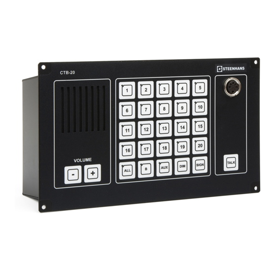
Installation & User Manual System CTB-100V 4. USER INSTRUCTIONS Operation from the operation panel. Up to 4 operation panels can be connected. Calls can be made from any operation panel to substations. And calls can be made from any operation panel to another by pressing respective line button. - Page 20 Installation & User Manual System CTB-100V Figure 1 & 2 CTB-10 & CTB-20 1..Monitor loudspeaker ..For communication and alarm signals. 2..Line Push Buttons ..Line selection switch with indication light, 1 -10 for CTB-10 ............ 1 – 20 for CTB-20 3..
-
Page 21: Make A Call To An Substation
Installation & User Manual System CTB-100V 4.1.1 Make a call to an substation. You can select the substation by pressing desired line push button. Steady green LED will indicate activated selection. If desired, the signal button SIGN may be pressed to give a tone signal to selected station. Talk from the operation panel is performed every time TALK button is pressed. -
Page 22: Make A Call To Group Of Substations
Installation & User Manual System CTB-100V 4.1.2 Make a call to group of substations. You can select group of substations by pressing respective line buttons from one of the four Operation panels. Only the operation panels can switch off and end the call •... -
Page 23: All Call
Installation & User Manual System CTB-100V 4.1.3 All Call The message and signal from the operation panel will be given to all substations, as a one-way message. It will be indicated by steady green LED in the ALL button only. Talk back from substations is closed in this mode. -
Page 24: Handsfree Operation
Installation & User Manual System CTB-100V 4.1.4 Handsfree operation Operation panel with gooseneck microphone MB-30G and footswitch • Press the FOOTSWITCH button . Speak clearly into the microphone. When the TALK button is released the operation panel will be in listening mode, and you will hear the communication from the selected station. -
Page 25: Receive A Call From An Substation
Installation & User Manual System CTB-100V 4.1.6 Receive a call from an substation. A call are indicated with flashing green LED in the push button and a beep tone in the monitor loudspeaker or extern loudspeaker. Will also activate extra signal unit if installed. Only the operationpanel can switch off and end the call. -
Page 26: Receive A Call From Two Or More Substations
Installation & User Manual System CTB-100V 4.1.7 Receive a call from two or more substations. Calls can be received from two or more substations at same time. The operation panel that is set to receive calls can select between calls from substations. -
Page 27: Aux Function
Installation & User Manual System CTB-100V 4.1.8 AUX function An external signal connected to the AUX input of the system, will be transferred to any selected station or group of stations if the AUX button is selected. (Example: Entertainment and VHF signal.) Other functions with higher priority will override this function. -
Page 28: Audio From External Audio To All
Installation & User Manual System CTB-100V 4.1.9 Audio from external audio to All Alarm (or any audio) from external system can be distributed trough the CTB-100 system. An potentional free contact and 0dB signal from the external system activate the system and the message will be addressed to all substations and operation panels. -
Page 29: Public Address Operation Of External System
Installation & User Manual System CTB-100V 4.1.10 Public Address Operation of external system The four last line push buttons on the operation panels can be set to access 1 to 4 public address zones. CTB-10 & CTB-10W_V01: Push button marked 7-8-9-10 CTB-20 &... -
Page 30: Emergency Public Address Operation
4.1.11 Emergency Public Address Operation. In order to comply with PA-requirements, two PA call stations are required: The CTB-100V system are designed for use with up to four operation panels that can be used as Emergency call stations. In addition one or more All call station (Ex. - Page 31 Installation & User Manual System CTB-100V With hand microphone ETC-1-TB (CTB-10 & CTB-20) • Press the PTT SWITCH marked “EMERGENCY PA-BUTTON” • Speak clearly into the microphone to give message. With hand microphone P-66 (CTB-10W_V01 & CTB- 20W_V01) • Press the PTT SWITCH marked “EMERGENCY PA-BUTTON”...
-
Page 32: Volume
Installation & User Manual System CTB-100V 4.1.12 Volume By pressing + or - buttons repeatedly, you can increase or decrease the listening volume in the ETB. This will also affect the volume for a parallel speaker connected to the ETB •... -
Page 33: Parallel Communication
Installation & User Manual System CTB-100V Parallel communication Function with operation from parallel microphone / loudspeaker located on bridge wings, or other locations near the operation panel, where parallel microphone / loudspeaker needed. Two parallel stations can be connected. Communication is set up by the operationpanel. -
Page 34: Operation
Installation & User Manual System CTB-100V 4.2.1 Operation Note! Line selection and signal have to be set up from the central unit. Operationpanel • Press the desired LINE button, the call is set up. Indicated by steady green LED Operationpanel •... -
Page 35: Operation From Substations
Installation & User Manual System CTB-100V Operation from substations. Calls can be made from substations to the operation panels by pressing the CALL push button. A call is indicated by a flashing green LED and a signal in the operation panel. The operation panel confirm the call by pressing respective line button. - Page 36 Installation & User Manual System CTB-100V Figure 14 Substation STB-5 PTT SWITCH Loudspeaker For communication from the central unit. Call Push button switch for call to central unit. 3. C ontact For handset HAS-1 or handheld microphone ETC-STB5 Handset HAS-1 with push to talk switch (PTT)
- Page 37 Installation & User Manual System CTB-100V Figure 17 Substation VH-10M Figure 18 Substation VHM-10 CABINET PTT SWITCH 10m cable Loudspeaker For communication from the central unit CALL Push button switch for call to the central unit Microphone P-66 fixed connected with PTT switch...
-
Page 38: Operation From Stb-1
Installation & User Manual System CTB-100V 4.3.1 Operation from STB-1 Substation Operationpanel • Press the CALL button. • Indicated with flashing green LED and a signal in the operation panels speaker for selected line. • Operator of the operation panel press respective LINE button, the call is set up. -
Page 39: Operation From Stb-3
Installation & User Manual System CTB-100V 4.3.3 Operation from STB-3 Substation Operationpanel • Press the CALL button. • Indicated with flashing green LED and a signal in the operation panels speaker for selected line. • Operator of the operation panel press respective LINE button, the call is set up. -
Page 40: Operation From Stb-5
Installation & User Manual System CTB-100V 4.3.4 Operation from STB-5 Substation Operationpanel • Press the CALL button . • Indicated with flashing green LED and a signal in the operation panels monitor loud speaker for selected line. • Operator of the operation panel press respective LINE button, the call is set up. -
Page 41: Operation From Stb-5Gn
Installation & User Manual System CTB-100V 4.3.5 Operation from STB-5GN Substation Operationpanel • Press the CALL button. • Indicated with flashing green LED and a signal in the operation panels speaker for selected line. • Operator of the operation panel press respective LINE button, the call is set up. -
Page 42: Operation From Vh-10M / Vh-10M-T
Installation & User Manual System CTB-100V 4.3.7 Operation from VH-10M / VH-10M-T Substation Operationpanel • Press CALL button. • Indicated with flashing green LED and a signal in the operation panels speaker for selected line. • Operator of the operation panel press respective LINE button, the call is set up. -
Page 43: Operation From Nebb-42Ex / Ex Loudspeaker
Installation & User Manual System CTB-100V 4.3.9 Operation from NEBB-42EX / EX Loudspeaker Substation Operationpanel • Press the CALL button. • Indicated with flashing green LED and a signal in the operation panels speaker for selected line. • Operator of the operation panel press respective LINE button, the call is set up. -
Page 44: Commissioning
Installation & User Manual System CTB-100V 5. COMMISSIONING General The CTB and CU- units and all sub equipments have been fully tested in our workshop before delivery. To ensure that everything is correct after installation and configuration of the system, do the following procedure before the system is ready for use. -
Page 45: Starting Up The System
Installation & User Manual System CTB-100V Starting up the system. The system has no On/Off switch for main power. Power switching is done from external equipment The system is always powered and ready for use and it’s only indicated when using the system. -
Page 46: Volume Control
Installation & User Manual System CTB-100V Volume control Pos. Operation Requirement Tested, ok Adjust sound pressure level, to convenient level if necessary Master volume line 1-5, 6-10, 11-15, 16-20 Ref. chapter 3.8 and dwg.CU-100:lo and CU-200_lo Trouble shooting. Most faults can be related to following problems Important! Use this trouble shooting together with chapter 3 Installation and Configuration Procedure Problems when operating from operation panels. - Page 47 Installation & User Manual System CTB-100V Level for call signal out to all Adjust trim potentiometer in the lines does not fulfil the central unit marked “adj. call requirement. signal out” to satisfactorily level. See chapter 3.8.3 General operating problems Instability.
- Page 48 Installation & User Manual System CTB-100V Problems when operating from substation or parallel station connected to an operation panel Pos. Failure event Description / Indication Recommended Action Operation from an substation No flashing green LED and a signal in 1. Check cable and terminal block...
-
Page 49: Installation Drawings And Datasheet
Installation & User Manual System CTB-100V 6. INSTALLATION DRAWINGS AND DATASHEET Installation drawings Item Description Doc.no System drawing....Single line diagram ................CTB-100_sl System drawing....System block diagram.................CTB-100_bd System drawing....Lay out terminals CTB-10, 20, CTB-10,20 W/01 ......CTB-1020_lo System drawing....Lay out terminals CU-100 ..............CU-100_lo System drawing.... - Page 50 Installation & User Manual System CTB-100V Substations and other equipment STB-1 ......Substation indoor wall mounted with call and answer button....STB-1_ds STB-2 ......Call box WP wall mounted for use together with VML-1520....STB-2_ds STB-3 ......WP Combined call-plug box w/relay unit signal device,....STB-3_ds PMT-7 ......
- Page 70 Depending on external 100V power amplifier Description: Output impedance: 100V per line CU-100 Central unit 10 lines for CTB-100V system Operates with CTB-10 panel unit AUX / Alarm input Signal oscillator 24 VDC power supply 100 V line output High power amplification by use of external 100V line power amplifier Document no.
- Page 71 Depending on external 100V power amplifier Description: Output impedance: 100V per line CU-200 Central unit 20 lines for CTB-100V system Operates with CTB-20 panel unit AUX / Alarm input Signal oscillator 24 VDC power supply 100 V line output High power amplification by use of external power amplifier Document no.
- Page 72 CTB-10 Talk-Back Systems Description: CTB-10 Operator panel CTB-10 with 10 lines selection Features Operates with CU-10 or CU-20 central unit Bridge Wing communciation facility All Call / Group Call facility Re-entrant monitor-speaker / microphone Connector for gooseneck or handheld microphone Dimable panel background light Extension buttons with memory light Buzzer indication of incoming calls...
- Page 73 CTB-20 Talk-Back Systems Description: CTB-20 Features Operator panel CTB-20 with 20 lines selection Operates with CU-20 central unit Bridge Wing communication facility All Call / Group Call facility Re-entrant monitor-speaker / microphone Connector for gooseneck or handheld microphone Dimable panel background light Extension buttons with memory light Buzzer indication of incoming calls Step volume control...
- Page 74 Talk-Back Systems CTB-10 W / V01 Description: CTB-10W / V01 Operator panel with 10 lines selection, Features and loudspeaker HP-8, bulkhead mounting. Option, microphone P-66 and P-66/10 Operates with CU-10 or CU-100 central unit Bridge Wing communication facilty All Call / Group Call facility Re-entrant monitor-speaker/microphone Dimable memory light Line buttons with memory light...
- Page 75 CTB-20W / V01 Talk-Back Systems Description: CTB-20W / V01 Operator panel with 20 lines selection, Features and loudspeaker HP-8, bulkhead mounting. Option, microphone P-66 and P-66/10 Operates with CU-20 or CU-200 central unit Bridge Wing communication facilty All Call / Group Call facility Re-entrant monitor-speaker/microphone Dimable memory light Line buttons with memory light...
- Page 76 VMT-603 ACM System - Stations Description: VMT-603: W/t PA station for interuption of Alarm signals for Features Emergency messages For wall mounting at muster or embarkment stations Technical data: Handheld mic.: 62A0005 Connection: Internal screw terminals Housing: ROSE Box Colour: Grey box / Black sign IP rating: IP-65...
- Page 77 HP-8 Loudspeakers Description: HP-8 Horn loudspeaker for use on open deck areas, eng room etc. Features WP, IP-67. Technical data: Manufacturer: DNH A/S Material / Colour: Polyamide / RAL 7035 Mounting: Bracket or flush Termination: 0,5m cable Weight: 0,75 kg IP-rating (UL Equivalent) IP-67 Max.
- Page 78 MB-30G Common Equipment Description: MB-30G Gooseneck microphone Features For use in: Public Address System and Talk-Back System Technical data: Manufacturer: Paso Type Electret Art.no. : MB30G Impedance: 2 K ohm Freq.response: 100 - 20000Hz. Sensitivity: 4mv/Pa. Supply: 1,1-9V. Front rear ratio: 10 dB Length: 430mm...
- Page 79 ETC-1-TB Talk-Back Systems Description: ETC-1-TB Handheld microphone for use with ETB and CTB control Features unit panels. Technical data: Type Dynamic Art.no. : ETC-1-TB Impedance: 200 ohm Freq.response: 200 - 4500Hz. Sensitivity: 1 mV/Pa. Polar pattern: Non directional Switch: Cable: 3-wires coiled cord w/ shield Plug: 5 pole din...
- Page 80 Common Equipment P-66 Description: Ø54 P-66 Features Watertight, salt water resistant handheld microphone- loudspeaker unit. Suitable for heavy-duty outdoor operation subject to noise disturbance. Delivered with 2 meter flexicable and plug. For use in: Public Address System and Talk-Back System. Technical data: Manufacturer: Holmberg &...
- Page 81 Common Equipment P-66-10 Description: Ø54 P-66/10 Watertight, salt water resistant handheld microphone- Features loudspeaker unit. Suitable for heavy-duty outdoor operation subject to noise disturbance. Delivered with 10 meter cord and plug. For use in: Public Address System and Talk-Back System 10 m cable Technical data: Manufacturer:...
- Page 82 AW8121 Public Address Systems Description: AW8121 19” 3 HU 120 W power amplifier Features 230 Vac / 24 Vdc power supply Technical data: Manufacturer: Paso Colour: Black Power AC: 120 W Constant voltage outputs: 100, 70, 50 V Constant impedance outputs: 16, 8 ohm 482,6...
- Page 83 AW8241 Public Address Systems Description: AW8241 19” 3 HU 240 W power amplifier Features 230 Vac / 24 Vdc power supply Technical data: Manufacturer: Paso Colour: Black Power AC: 240 W Constant voltage outputs: 100, 70, 50 V 482,6 Constant impedance outputs: 16, 8 ohm SERIES...
- Page 84 Public Address Systems P8501 Technical data: Manufacturer: Paso Colour: Black Features Dimensions: 482 x 133 x 420 mm Power AC: 500 W Constant voltage outputs: 100, 70, 50, 25 V Constant impedance outputs: 20, 9.4, 5, 1.25 ohm Distortion at rated power: <...
- Page 85 Integrated Communication System RS-3D FRONT VIEW Description: RS-3D 3 HU 19” cabinet, prepared for amplifier Features SERIES POWER AMPLIFIER AW8121, AW8241 and P-8501 dB +40 -6 OUTPUT LEVEL OVERL. ON with all necessary terminals for external 230 Vac / 24 Vdc in and out signals BASS TREBLE MASTER VOLUME...
- Page 86 STB-1 Talk-Back Systems Description: STB-1 Talk-Back substation, designed for use in cabins, Features messrooms, etc. Delivered for bulkhead mounting Call-button for calling Master unit Privacy Talk-button with privacy off function. Technical data: Connections: Screw terminals Colour: Black front IP rating IP-44 Dimensions: See dwg.
- Page 87 Talk-Back Systems STB-2 Description: STB-2 Calling box Features Delivered for bulkhead mounting Call-button for calling Master unit Forming a loudspeaking Talk-Back Substation together with a horn loudspeaker. Technical data: Connections: Screw terminals Colour: Grey IP rating IP-66 Dimensions: See dwg. beside Weight: 0,3 kg Mounting hole...
- Page 88 STB-3 Talk-Back Systems Description: STB-3 Calling unit Features Delivered for bulkhead mounting Call-button for calling Master unit Call-button with LED for incoming call indication Socket with dust-cap for connection of headset or microphone Built-in relay circuit for operation of external signalling devices.
- Page 89 Analogue Telephone System P-MT7 Description: P-MT7 Headset for Analogue Telephone System connected Features through HSB-01 or HSB-0.2 Standard with 10 meter cable and plug. To be used in noisy areas. Includes headset holder. Technical data: 10m cable Connections: 4 pin Amphenol ( C16-1 ) Headset: Peltor MT 7H7A Colour:...
- Page 90 STB-5 Talk-Back Systems Description: STB-5 Talk-Back substation, designed for multipurpose indoor Features use ( engine room ) Delivered for flush or bulkhead mounting Call button for calling Master unit Built-in relay circuit for operating of external signalling devices. Loudspeaker Socket for handset or handheld microphone Technical data: Material / Colour: Aluminium / black...
- Page 91 STB-5GN Talk-Back Systems Description: STB-5GN · Talk-Back substation, designed for multipurpose indoor Features use ( engine room ) · Delivered for flush or bulkhead mounting · Call button for calling Master unit · Built-in relay circuit for operating of external signalling devices.
- Page 92 HAS-1 Talk-Back Systems Description: HAS-1 Handset with cradle designed for use together with Features Talk-back substation STB-5 Technical data: Colour: Black Material: Metal ( cradle ) / plastic ( handset ) Spiralcord: Approx. 1,2 m Plug: 5 pin DIN Switch: ON / OFF Weight: 0,55 kg...
- Page 93 ETC-STB5 Talk-Back Systems Description: ETC-STB5 Handheld microphone configurated for substation STB-5 Features Technical data: Type Dynamic Art.no. : ETC-STB5 Impedance: 200 ohm Freq.response: 200 - 4500Hz. Sensitivity: 1 mV/Pa. Polar pattern: Non directional Switch: Cable: 3-wires coiled cord w/ shield Plug: 5 pole din Accessories:...
- Page 94 VH-10M Talk-Back System Description: VH-10M Portable deck loudspeaker with callbox Features Delivered with 10 meter cable and plug Technical data: Material: Anodized aluminium ( Backplate ) / ABS ( Speaker ) Colour: Black ( Backplate ) / Grey ( Speaker ) Dimensions: See dwg.
- Page 95 VH-10M-T Talk-Back System Description: VH-10M-T Portable deck loudspeaker 100V with callbox Features Delivered with 10 meter cable and plug Technical data: Material: Anodized aluminium ( Backplate ) / ABS ( Speaker ) Colour: Black ( Backplate ) / Grey ( Speaker ) Dimensions: See dwg.
- Page 96 CD-2 Talk-Back Systems Description: CD-2 Watertight plug box Features Designed to be used together with substations, VH-10M and VH-10MT Socket with dustcap Delivered for bulkhead mounting Suitable for installation in noisy areas PG11 Technical data: Connections: Screw terminals Colour: Grey Mounting hole IP rating: IP-66...
- Page 97 VHM-10 Talk-Back System Description: VHM-10 Special substation with hand microphone and callbox in a Features cabinet Technical data: Material: Polycarbonate ( Cabinet ) Colour: Grey ( Cabinet ) Dimensions: See dwg. above IP rating: IP-66 Weight: 2,5 kg Microphone P-66: Colour: Black IP class:...
- Page 98 VHM-10T Talk-Back System Description: VHM-10T Special substation with hand microphone and callbox in a Features cabinet. For connection to 100V loudspeaker Technical data: Material: Polycarbonate ( Cabinet ) Colour: Grey ( Cabinet ) Dimensions: See dwg. above IP rating: IP-66 Weight: 2,5 kg Microphone P-66:...
- Page 99 HE-112M Talk-Back Systems Description: HE-112M Talk-Back Substation, designed for use in open deck Features areas Delivered for bulkhead mounting Call-button for calling Master unit Technical data: Connections: Screw terminals Colour: Grey IP rating: IP-66 Dimensions: See dwg. beside Weight: 0,4 kg Mounting holes 4 mm CALL...
- Page 100 HE-112MT Talk-Back Systems Description: HE-112MT Talk-Back Substation, designed for use in open deck areas Features To be used with 100 volt line amplifiers Delivered for bulkhead mounting Call-button for calling Master unit Technical data: Connections: Screw terminals Transformer: For 100V line ampl. Colour: Grey IP rating:...
- Page 101 NEBB-42-EX Talk-Back Systems 85mm Description: NEBB-42EX Features Explosion-proof calling box for hazardous areas Delivered for bulkhead mounting Call-button for calling Master unit Forming a loudspeaking Talk-Back Substation together CEAG GHG 411 Ui 690V with a EX-horn loudspeaker. EEx de IIC T6 PTB Nr.Ex-87.B.1009 Technical data: Connections:...
- Page 102 STB-6 Command Talk-Back System Description: STB-6 Substation for indoor bridge wing Features Parallel microphone / loudspeaker for ETB and CTB operator panels Delivered for flush or bulkhead mounting Socket for handheld microphone Technical data: Dimensions (WxHxD): 144 x 96 x 44 Mounting: 4x 4mm screws Ø...
- Page 103 STB-6GN Command Talk-Back System Description: STB-6GN Substation with gooseneck microphone for indoor Features bridge wing Parallel microphone / loudspeaker for ETB and CTB operator panels Delivered for flush or bulkhead mounting Technical data: Dimensions (WxHxD): 144 x 96 x 44 Mounting: 4x 4mm screws Weight:...
- Page 104 SB-4 Talk-Back Systems Description: SB-4 Is a watertight socket box Features Is designed to be used together with handheld microphone or headset units Has socket with dustcap Is delivered for bulkhead mounting is suitable for installation in noisy areas Technical data: Connections: Screw terminals Colour:...
- Page 105 Talk-Back Sy stems CTBOKS Talk-Back Systems WBOKS Description: Ø 5 WBOKS Box for bulkhead mounting for ETB and CTB operation Features panels Ø 22.5 Ø 22.5 Technical data: Colour: Black finish Material: Aluminium Dimensions: See dwg. beside Mounting: 4x 5 mm holes Weight: 415 g Document no.
- Page 106 STBOKS5 Command Talk-Back System Description: STBOKS5 Box for bulkhead mounting of STB-5 & STB-5GN Features Technical data: Dimensions (WxHxD): 144 x 144 x 59 Mounting: 4x 4mm screws Ø 2,5 Weight: Approx. 0,215kg Ø 5 Housing: Aluminium elox. Colour: Black Cable entry: Rear side Ø...
- Page 107 STBOKS Command Talk-Back System Description: STBOKS Box for bulkhead mounting of STB-6 & STB-6GN Features Technical data: Dimensions (WxHxD): 144 x 96 x 47 Mounting: 4x 4mm screws Ø 4 Weight: Approx. 0,1kg Housing: Aluminium elox. Colour: Black Cable entry: Rear side Ø...
- Page 108 VML-1520 Loudspeakers Description: VML-1520 Is a general purpose15 Watt horn loudspeaker Features w/transformer for use on deck areas, eng. room etc. To be used together with ACM system stations Technical data: Rated power: 15 Watt RMS Impedance: 20 ohm Freq.range: 275 - 7.000 Hz SPL at 1kHz: 106dB/1W/1m...
- Page 109 VML-15T Loudspeakers Description: VML-15T Is a general purpose 15 Watt horn loudspeaker w/ Features transformer for use on deck areas, eng. room etc. To be used together with 100V line amplifier Technical data: Rated power: 15 Watt Tranf. tapping: See dwg. beside Freq.
- Page 110 SPS-4 Power Supply Description: Features SPS-4 Ver.2.0 Power supply 115/ 230 VAC to 24VDC 4A with autoswitch relay for main supply fails and powerfailure. Technical data: Input voltage AC: AC100 - 120/220-240V Autoselect Input voltage DC: DC220 - 375V Hold-up time: >20 ms (AC 196V) >20 ms (AC 100V) Rated Input current:...
- Page 111 BLK5 Common Equipment Description: BLK5 Optical signalling device of rugged design for indoor and Features outdoor use with compensation valve to prevent condensation water Delivered in two versions: for 24 Vdc or 230 Vac. Technical data: Manufacturer: Comax Material: Case of aluminium Dome of ABS Colour: Red, amber, green, blue , clear...
- Page 112 EHS-24 Signal Units Description: EHS-24 Rotary light for all systems. Features To be mounted in noisy areas etc Technical data: Manufacturer: Sunbeam Type / art.no.: EHS-24 Colour available: Orange-red-green-blue Rotation speed: 180 rpm Operation volt.: 24V DC 220mm Rated current: 2.6A Dimensions: See dwg.
- Page 113 A-100 Signal Devices Description: A-100 Audible signal device for all systems. Features Signal device do have the possibility for many different 87mm tones. To be wall-mounted in noisy areas like engine room etc. Ø=6mm 87mm Technical data: 101mm Manufacturer: European Safety Systems 77mm 114mm Type/art.no.:...
- Page 114 U2410 Talk-Back Systems Description: U2410 Cable inlet Foot switch for VOC, ETB and CTB systems Features Technical data: Colour: Black Type: 1 pole-switch Voltage: 250 Vac Current: Document no. U2410_ds rev.02 2004.08.30 Article no. U2410 www.zenitel.biz\Communication & Security Systems\Zenitel Marine...
- Page 115 A100K10864 STENTOFON and VINGTOR products are developed and marketed by Zenitel Norway AS. The company’s Quality Assurance System is certified to meet the requirements in NS-EN ISO 9001:2008. Zenitel Norway AS reserves the right to modify designs and alter specifications without prior notice, in pursuance of a policy of continuous improvement. © 2009 Zenitel Norway AS.
Need help?
Do you have a question about the CTB-100V and is the answer not in the manual?
Questions and answers