Table of Contents
Advertisement
Quick Links
Advertisement
Table of Contents

Related Manuals for thomann LED-Commander 16/2


Summary of Contents for thomann LED-Commander 16/2
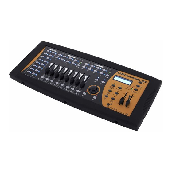
- Page 1 LED-Commander 16/2 DMX-controller user manual...
- Page 2 Musikhaus Thomann Thomann GmbH Hans-Thomann-Straße 1 96138 Burgebrach Germany Telephone: +49 (0) 9546 9223-0 E-mail: info@thomann.de Internet: www.thomann.de 06.08.2015, ID: 251852 | SW V1.0...
-
Page 3: Table Of Contents
Table of contents Table of contents General notes............................... 4 Safety instructions............................. 6 Features............................... 10 Installation..............................11 Starting up..............................12 Connections and operating elements................... 13 Operation..............................22 Technical specifications........................44 Protecting the environment......................45 LED-Commander 16/2... -
Page 4: General Notes
General notes General notes This user manual contains important information on safe operation of the device. Read and follow all safety notes and all instructions. Save this manual for future reference. Make sure that it is available to all persons using this device. If you sell the device, include the manual for the next owner. - Page 5 General notes Warning signs Type of danger Warning – danger zone. LED-Commander 16/2...
-
Page 6: Safety Instructions
Safety instructions Safety instructions Intended use This device is intended to be used to control spot lights, dimmers, light effects, moving heads or other DMX-controlled devices. Use the device only as described in this user manual. Any other use or use under other operating conditions is considered to be improper and may result in personal injury or property damage. - Page 7 Choking hazard! Ensure that children do not detach any small parts (e.g. knobs or the like) from the unit. They could swallow the pieces and choke! Never let children unattended use electrical devices. LED-Commander 16/2...
- Page 8 Safety instructions NOTICE! External power supply The device is powered by an external power supply. Before connecting the external power supply, ensure that the input voltage (AC outlet) matches the voltage rating of the device and that the AC outlet is protected by a residual cur‐ rent circuit breaker.
- Page 9 Safety instructions NOTICE! Operating conditions This device has been designed for indoor use only. To prevent damage, never expose the device to any liquid or moisture. Avoid direct sunlight, heavy dirt, and strong vibrations. LED-Commander 16/2...
-
Page 10: Features
Features Features 16 devices controllable via DMX-512 2 × 8 memory slots each for scenes and chases Faders for fade and scene time and speed, dimmer etc. Operation modes: automatic, sound controlled and manual Blackout and Full-on-function Separate channel assignment Backup and firmware update via USB USB port for desk light 19"... -
Page 11: Installation
The unit has been designed for rack mounting in a standard 19-inch rack. It occupies four rack units (RU). DMX connection A 3-pin XLR socket is used as DMX output. The following diagram and table show the pin assignment of the XLR socket. Ground DMX data (–) DMX data (+) LED-Commander 16/2... -
Page 12: Starting Up
Starting up Starting up Establish all connections as long as the unit is switched off. Use the shortest possible high- quality cables for all connections. Connecting the power supply Connect the included power adapter to the 9 V input of the device and then plug the mains plug into the power outlet. -
Page 13: Connections And Operating Elements
Connections and operating elements Connections and operating elements Front panel LED-Commander 16/2... - Page 14 Connections and operating elements 1 FIXTURE Buttons 1 to 16 to select the control channels. The corresponding indicator LED shows whether the respective channel is activated (LED on) or deactivated (LED off). 2 SCENE Eight buttons with double assignment for enabling / disabling of up to 16 scenes. The indicator LEDs show which scenes are enabled (LED is on).
- Page 15 Button to change the operation mode. The corresponding LED shows the active operating mode: Auto, Music or Manual. 9 SPEED fader Slider to manually adjust the chase speed during playback. 10 FADE fader Slider to manually adjust the fade time during playback. LED-Commander 16/2...
- Page 16 Connections and operating elements 11 BLACKOUT button Button to turn the BLACKOUT function on or off. The corresponding indicator LED shows whether the function is activated (LED on) or deactivated (LED off). 12 FULL ON button Button to turn the FULL ON function on or off. The corresponding indicator LED shows whether the function is acti‐ vated (LED on) or deactivated (LED off).
- Page 17 With these buttons you can activate the AUX channels (corresponding LED is lit) or deactivate them (LED is off). 21 DIMMER fader Slider to manually adjust the DIMMER function. Press the corresponding flash button 8 to activate the slider control. LED-Commander 16/2...
- Page 18 Connections and operating elements 22 STROBE fader Slider to manually adjust the STROBE function. Press the corresponding flash button 7 to activate the slider control. 23 SCENE fader Slider to manually control a scene. Press the corresponding flash button 6 to activate the slider control. 24 SPEED fader Slider to manually control the speed of a scene or a chase.
- Page 19 Slider to manually control the colour intensity RED. Press the corresponding flash button 2 to activate the slider con‐ trol. 28 FUNCTION fader Controller for manual adjustment of an active function. Press the corresponding flash button 1 to activate the slider control. LED-Commander 16/2...
- Page 20 Connections and operating elements Rear panel DMX-controller...
- Page 21 32 Audio input (line level, 100 mV to 1 V 33 MIDI OUT output socket. 34 MIDI THRU port. 35 MIDI IN input socket. 36 Connection socket for the 9 V power adapter for voltage supply. 37 Main switch to turn the unit on or off. LED-Commander 16/2...
-
Page 22: Operation
Operation Operation After turning the unit on, it will run a short self-test. Then the unit automatically switches to operating mode ‘Manual’ and is ready for use. Selecting the operating mode The LED Commander 16/2 operates in three different modes. To change the mode, press the [MODE] button repeatedly until the desired mode appears in the display and the corre‐... - Page 23 Press the flash button for the function you want to assign. Repeat steps 2 to 5 to allocate the remaining sliders with functions. Example: If the RED function (flash button 2) is assigned to DMX channel 21, the display shows the following values: LED-Commander 16/2...
- Page 24 Operation Cancelling channel assignment ½ CLEAR] button pressed for three seconds. Keep the [PATCH Deselect all active FIXTURE channels (all blue FIXTURE-LEDs off). Use the [FADE] and [SPEED] sliders to select the DMX channel whose assignment you want to cancel. Press the respective flash button (1 to 8) to cancel the channel assignment.
- Page 25 Select the desired channel range using the [SPEED] sliders (1, 21, 41, 61 etc.). Select the desired DMX channel via the [FADE] slider. Keep the flash button [RED] pressed for three seconds. ð The display shows the following message: LED-Commander 16/2...
- Page 26 Operation Now, the channel RED of FIXTURE 01 can be controlled via the [DIMMER] control that is assigned to the channel FIXTURE 01. Repeat steps 4 to 6 to allocate the remaining channels of FIXTURE 01. The previously selected FIXTURE channel is displayed with the letter ‘M’ in the display. In the example, this means that the [DIMMER] control that is assigned to channel FIXTURE 01 can control the maximum value of RED (CH 2).
- Page 27 Press the [SCENE] button to select the desired scene. If needed, toggle between both memory banks via the shift button. You can link a number of scenes together and control them using the [FADE] slider. The LEDs of all selected scenes light up blue. LED-Commander 16/2...
- Page 28 Operation Programming scenes ½ RECORD] pressed for three seconds to change to the oper‐ Keep the button [PROGRAM ating mode Programming/Recording. Use the [FIXTURE] buttons to select the channel that you want to programme. Use the flash controls 1 to 8 to set the desired values. Press the [SCENE] button to select a memory slot.
- Page 29 ½ CLEAR] pressed for three seconds to delete all initial values of Keep the button [PATCH the fader function. Press the [CHASE] button to select the desired chase. If needed, toggle between both memory banks via the shift button. LED-Commander 16/2...
- Page 30 Operation Programming chases ½ RECORD] button pressed for three seconds to change to the oper‐ Keep the [PROGRAM ating mode Programming/Recording. Press the [CHASE] buttons to select the desired chase. If needed, toggle between both memory banks via the shift button. ð...
- Page 31 Repeat steps 4 to 7 to insert further programme steps. The 16 memory slots can be assigned to a total of 2,000 programme steps. ½ RECORD] pressed for three seconds to exit the recording Keep the button [PROGRAM mode. LED-Commander 16/2...
- Page 32 Operation Deleting a programme step ½ RECORD] pressed for three seconds to change to the oper‐ Keep the button [PROGRAM ating mode Programming/Recording. Press the [CHASE] buttons to select the chase from which you want to delete a step. If needed, toggle between both memory banks via the shift button.
- Page 33 If needed, toggle between both memory banks ‘CHASE’ via the shift button. ½ DEL] button and then the Chase button of the chase that you want to Press the [TAP delete. ½ RECORD] pressed for three seconds to exit the recording Keep the button [PROGRAM mode. LED-Commander 16/2...
- Page 34 Operation Assigning DMX channels to AUX channels ½ RECORD] pressed for three seconds to change to the oper‐ Keep the button [PROGRAM ating mode Programming/Recording. Use the [FADE] and [SPEED] sliders to select the DMX channel that you want to assign. Press the [AUX1] or [AUX2] button to assign the DMX channel to the respective AUX channel.
- Page 35 Press the flash button of the desired control to assign the DMX channel. Repeat steps 2 and 3 to assign any number of DMX channels. ½ RECORD] pressed for three seconds to exit the recording Keep the button [PROGRAM mode. LED-Commander 16/2...
- Page 36 Operation Renaming flash functions Switch the device off ½ RECORD], [DIMMER] and [PATCH ½ CLEAR] pressed simulta‐ Keep the buttons [PROGRAM neously and turn the device on again. ð The following message appears in the display after two seconds: Press the flash button of the function that you want to rename. Now you can use the joystick to change the description in the display (move it right / left to move the cursor, move it up / down to change the character).
- Page 37 SCENE1-16 Turning scenes 1-16 on / off 16-31 CHASE1-16 Turning chases 1-16 on / off MANUAL Manual show control MUSIC Sound controlled show AUTO Automatic show AUX1 Turning AUX1 on / off AUX2 Turning AUX2 on / off LED-Commander 16/2...
- Page 38 Operation MIDI value Function Description Manual show control Manual show control Automatic show … … … BLACK OUT Function BLACK OUT active DMX-controller...
- Page 39 ‘Press fixture Press the button of the FIXTURE channel whose settings you want to save. ð The saving progress is shown on the display. All channel settings are stored together in the file ‘led-commander 16-2’ on the USB drive. LED-Commander 16/2...
- Page 40 Operation Loading stored settings You can load saved device settings from a USB drive into the units memory. Connect the USB drive with the saved setting values to the USB port of the device. Keep the buttons [MODE] and pressed for two seconds until the display shows the ½...
- Page 41 After resetting to factory defaults, the FIXTURE channels are set up as follows: FIXTURE 1 FIXTURE 2 FIXTURE 3 … FIXTURE 16 FUN CH1 FUN CH11 FUN CH21 FUN CH151 Red CH2 Red CH12 Red CH22 Red CH152 LED-Commander 16/2...
- Page 42 Operation FIXTURE 1 FIXTURE 2 FIXTURE 3 … FIXTURE 16 Green CH3 Green CH13 Green CH23 Green CH153 Blue CH4 Blue CH14 Blue CH24 Blue CH154 SPEED CH5 SPEED CH15 SPEED CH25 SPEED CH155 COLOUR CH6 COLOUR CH16 COLOUR CH26 COLOUR CH156 STROBE CH7 STROBE CH17...
- Page 43 After the installation is complete, the display shows the message ‘Update succeeded Please reboot’ . Then, turn off the device and after a few seconds turn it on again. ð The unit will now start with the updated firmware. LED-Commander 16/2...
-
Page 44: Technical Specifications
Technical specifications Technical specifications Operating supply voltage DC 9…12 V Communication protocol DMX 512 Dimensions (W × D × H) 482 mm × 175 mm × 75 mm Weight 3.5 kg DMX-controller... -
Page 45: Protecting The Environment
Dispose of this device through an approved waste disposal firm or through your local waste facility. When discarding the device, comply with the rules and regulations that apply in your country. If in doubt, consult your local waste disposal facility. LED-Commander 16/2... - Page 46 Notes DMX-controller...
- Page 48 Musikhaus Thomann · Hans-Thomann-Straße 1 · 96138 Burgebrach · Germany · www.thomann.de...
Need help?
Do you have a question about the LED-Commander 16/2 and is the answer not in the manual?
Questions and answers