
Related Manuals for Interlogix UltraSync RS3130


Summary of Contents for Interlogix UltraSync RS3130
- Page 1 UltraSync Wi Fi IP Camera Installation Guide P/N 466-5236 • REV B • ISS 28APR16 © 2016 United Technologies Corporation. All rights reserved...
-
Page 2: Table Of Contents
Contents Installation environment ............3 Package contents ..............4 Cable requirements ..............6 Camera description ..............7 Accessing the SD card ............8 Wedge Camera ..............9 Desktop Camera ..............9 Mounting the Wedge Camera ..........10 Mounting the Desktop Camera ..........13 Quick Setup ................16 Setting up Ethernet/Wi Fi transmission ........ -
Page 3: Installation Environment
Installation environment When installing your product, consider these factors: • Electrical: Install electrical wiring carefully. It should be done by qualified service personnel. Always use a proper PoE switch or a 12 VDC UL listed Class 2 or CE certified power supply to power the camera. -
Page 4: Package Contents
Package contents Check the package and contents for visible damage. If any components are damaged or missing, do not attempt to use the unit; contact the supplier immediately. If the unit is returned, it must be shipped back in its original packaging. UltraSync Wi Fi IP Wedge Camera Transformer P/N 466-5236 •... - Page 5 UltraSync Wi Fi IP Desktop Camera Power Supply (US) P/N 466-5236 • REV B • ISS 28APR16 © 2016 United Technologies Corporation. All rights reserved...
-
Page 6: Cable Requirements
One power supply with interchangeable plugs is included for SKU number RS-3131. Power Supply (EU) Power Supply (UK) Power Supply (AUS) CAUTION: Use direct plug-in UL listed power supplies marked Class 2/CE certified or LPS (limited power source) of the required output rating as listed on the unit. -
Page 7: Camera Description
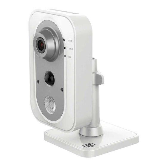
Camera description – Wedge Camera Camera cover/housing Alarm and Audio port Lens Reset/WPS button SD card Converter pan Ethernet RJ45 PoE port Antenna Power supply Microphone Base P/N 466-5236 • REV B • ISS 28APR16 © 2016 United Technologies Corporation. All rights reserved... - Page 8 Camera description – Desktop Camera 1. Lens 2. Microphone 3. IR LED 4. PIR 5. Light sensor 6. SD card slot 7. Bracket stand 8. RJ45 network port 9. WPS/RET button 10. Alarm I/O 11. DC12V port P/N 466-5236 • REV B • ISS 28APR16 ©...
-
Page 9: Accessing The Sd Card
Accessing the SD card Wedge Camera An 8GB Micro SD card is pre-installed with the camera; (see item 3 in Camera Description, page 6). Desktop Camera An 8GB Micro SD card is pre-installed with the camera. If desired, the Micro SD Card can be replaced with up to 64GB for local storage as a backup in case, for example, the network fails. -
Page 10: Mounting The Wedge Camera
Mounting the Wedge Camera To mount the wedge camera on a wall or ceiling: Drill the holes for the mounting hardware in the mounting surface using the supplied drill template. To route the cables from the base of the camera, drill a cable access hole in the mounting surface. - Page 11 3. Loosen the screws with the tamper-resistant hex wrench (supplied) to remove the camera cover. 4. Mount the camera base to the converter pan or mounting surface, depending on the installation. 5. Use the supplied lens alignment tool to adjust the pan [±30°...
- Page 12 6. Re-attach the dome cover to the camera. Wedge Camera Dimensions Wedge Camera Mounting Plate Dimensions P/N 466-5236 • REV B • ISS 28APR16 © 2016 United Technologies Corporation. All rights reserved...
-
Page 13: Mounting The Desktop Camera
Mounting the Desktop Camera 1. Drill the screw holes according to the drill template. 2. Disassemble the 3- axis bracket. Hold the base with one hand, and rotate the pole anticlockwise to disassemble the pole from the base. 3. Install the fixed tray to the ceiling with the supplied screws. 4. - Page 14 5. Install the camera to the bracket. 90° 6. Adjust surveillance Knob angle 360° 7. Loosen the knob to adjust the panning position and tilting position. 8. After adjusting the angle of the camera to the desired position, fasten the knob. P/N 466-5236 •...
- Page 15 Desktop Camera Dimensions P/N 466-5236 • REV B • ISS 28APR16 © 2016 United Technologies Corporation. All rights reserved...
-
Page 16: Quick Setup
Quick Setup Note: If the light source where the camera is installed experiences rapid, wide variations in lighting, the camera may not operate as intended. To quickly put the camera into operation: 1. Prepare the mounting surface. 2 Mount the camera using the appropriate fasteners. See “Mounting the Wedge Camera”... -
Page 17: Wi Fi Signal Strength
Wi Fi Signal Strength Wi Fi signal strength can be checked in the Network section of the TruVision Browser. Use the scale below to measure if actions are needed to improve performance. Below 65 65-75 75-85 Very Poor Good Good Excellent 85+ –... -
Page 18: Add Cameras To A Wi Fi Network
2. Connect the camera to your router with an Ethernet cable. 3. Launch TruVision Device Manager. Note: Use the included CD or download at www.interlogix.com/video 4. Verify that the camera is found in the main camera selection window. 5. Select the camera you would like to configure. -
Page 19: Add Cameras To Ultrasync
14. Click Save on the bottom of the screen. Note: Do not hit Connect in the WPS Section. 15. Below the Key 1 box, verify that “Your Network” is now showing connected. 16. Repeat steps for any additional cameras. Note: Do not exit the TruVision Camera Configurator browser. You are now connected to the network via Wi Fi! Add Cameras to UltraSync Ensure proper installation of camera hardware and adding cameras... -
Page 20: Reboot Cameras
Reboot Cameras Reopen TruVision IP Camera Configurator (Browser) Select System from the menu on the left. 10. Select Maintenance from the middle menu. 11. Select Reboot. i) Select OK when asked if you want to reboot the unit. ii) Note: Reboot may take 1-2 minutes. 12. -
Page 21: Program Event Triggered Camera Clips
Click Latest Clip to view the last recorded clip from a specific camera. Program Event Triggered camera clips Cameras can be programmed to automatically record when selected events occur. This is achieved by creating a scene. 1. Click More on the bottom of the screen. 2. - Page 22 Select the Scene to Configure and type Scene Name. Select the Scene Trigger. Select Alarm System under Action Device. Select Trigger Camera Video Clip under Action Type. P/N 466-5236 • REV B • ISS 28APR16 © 2016 United Technologies Corporation. All rights reserved...
- Page 23 Select the Camera(s) which will record when the scene is triggered. Clips are recorded on the Micro SD card installed in the camera and are linked to events in History. See page 22 to see how to view event triggered clips. P/N 466-5236 •...
- Page 24 View Event Triggered clips in History 1. Click More tab on bottom of the screen. 2. Click History. 3. Find the Event you wish to view using Oldest, Prev, Next, and Latest buttons. Once you find the clip you wish to view, click Play Video Clip. P/N 466-5236 •...
- Page 25 Remove Camera from UltraSync (if needed) 1. Click the More tab on the bottom of the Screen. 2. Click Settings 3. Select Cameras under Settings Selector 4. Select the camera you with to remove. 5. Delete text in Camera Name, IP Address and MAC Address. 6.
-
Page 26: Change Default Camera Settings
3. Change settings as desired such as video quality, frame rate, pre and post recording times. 4. For detailed instructions on using TruVision Navigator, go to www.interlogix.com/video Note: To find the IP address of a camera connected to UltraSync, go to Settings > Cameras in the UltraSync App. -
Page 27: Alternatives For Adding Cameras
Alternatives for Adding Cameras via Wi Fi (using Windows PC for setup) Power up the camera. (Boot up may take 1-2 minutes) From your Windows PC, find and connect to your camera in the Wi Fi network list. Go to Network and Sharing Center. Control Panel >... -
Page 28: Via Ethernet (Non-Dhcp, Using Windows Pc For Setup)
via Ethernet (non-DHCP, using Windows PC for setup) Power up the camera. (Boot up may take 1-2 minutes) From your Windows PC, find and connect to your camera in the Wi Fi network list. Go to Network and Sharing Center. Control Panel >... -
Page 29: Troubleshooting
Troubleshooting Troubleshooting/FAQ Camera is not showing in list of Wi Fi networks. Cause Solution The camera takes up to 90 It will not show in Wi Fi seconds to boot up. Networks until this is complete. The camera has previously been Perform a factory reset to setup and ad hoc mode was broadcast the camera again. - Page 30 The camera was added in the setup process, but the video doesn’t show in the Cameras tab. Cause Solution After completing the setup process, the camera may take Wait for the process to complete up to 2 minutes to full sync and show in the UltraSync App.
-
Page 31: Specifications
Specifications UltraSync Wi Fi IP Wedge Camera Electrical Voltage input 12 VDC, PoE (IEEE 802.3af) Power consumption Max. 5 W Wi Fi parameters Wi Fi standard IEEE802.11b/g/n Frequency range 2.4 to 2.4835 GHz Communication Support 20/40 MHz bandwidth Security 64/128-bit WEP, WPA/WPA2, WPA- PSK/WPA2-PSK, WPS Transmission rate 11b: 11Mbps, 11g: 54Mbps, 11n: up... - Page 32 UltraSync Wi Fi IP Desktop Camera Electrical Voltage input DC12V±10%, PoE (IEEE 802.3af) Power consumption Max. 5.9W Wi Fi parameters Wi Fi standard IEEE802.11b/g/n Frequency range 2.4 to 2.4835 GHz Communication Support 20/40 MHz bandwidth Security 64/128-bit WEP, WPA/WPA2, WPA- PSK/WPA2-PSK, WPS Transmission rate 11b: 11Mbps, 11g: 54Mbps, 11n:...
- Page 33 Copyright © 2016 United Technologies Corporation. All rights reserved. All trademarks are the property of their respective owners. Interlogix is part of UTC Climate, Controls & Security, a unit of United Technologies Corporation. Manufacturer Interogix 2955 Red Hill Avenue, Costa Mesa, CA 92626-5923, USA Authorized EU manufacturing representative: UTC Fire &...
- Page 34 Federal Communication Commission (FCC) Radiation Exposure Statement This equipment complies with FCC radiation exposure set forth for an uncontrolled environment. In order to avoid the possibility of exceeding the FCC radio frequency exposure limits, human proximity to the antenna shall not be less than 20 cm (8 inches) during normal operation.
- Page 35 use of the equipment. National Restrictions This device is intended for home and office use in all EU countries (and other countries following the EU directive 2014/53/EU) without any limitation except for the countries mentioned below: Country Restriction Reasons/remarks Bulgaria None General authorization required for outdoor use and public service...
- Page 36 only for purposes of gathering telemetry information for automated monitoring and resources accounting systems or security systems. 2.3. Maximum mean e.i.r.p. density is 10 mW/MHz. Maximum 100 mW e.i.r.p. indoor applications. e.i.r.p. ≤100 mW with built-in antenna with Ukraine Limited implementation amplification factor up to 6 dBi.
- Page 37 For more information see: www.utcfssecurityproducts.eu/recycle/ Contact For contact information, see www.interlogix.com or www.utcfssecurityproducts.eu. information P/N 466-5236 • REV B • ISS 28APR16 © 2016 United Technologies Corporation. All rights reserved...
- Page 38 THERE WILL BE NO DEATH, PERSONAL INJURY, AND/OR PROPERTY DAMAGE AS A RESULT. WHILE INTERLOGIX UNDERTAKES TO REDUCE THE PROBABILITY THAT A THIRD PARTY MAY HACK, COMPROMISE OR CIRCUMVENT ITS SECURITY PRODUCTS OR RELATED SOFTWARE, ANY SECURITY PRODUCT OR SOFTWARE MANUFACTURED, SOLD OR LICENSED BY INTERLOGIX, MAY STILL BE HACKED, COMPROMISED AND/OR CIRCUMVENTED.
Need help?
Do you have a question about the UltraSync RS3130 and is the answer not in the manual?
Questions and answers