Table of Contents
Advertisement
Advertisement
Table of Contents
Troubleshooting

Subscribe to Our Youtube Channel
Related Manuals for Elsist MISSION 1000


Summary of Contents for Elsist MISSION 1000
- Page 1 Mission 1K-2K-3K Single Phase UPS Uninterruptible Power Systems...
-
Page 2: Table Of Contents
MISSION 1K●2K●3K SINGLE PHASE Contents 1.Safety instruction ............................3 1.1 Safety instruction ........................... 3 1.2 Symbols indication ..........................3 2.Product Introduction ........................... 4 2.1 The appearance of the product ......................4 2.2 The principle of the product ........................5 2.3 Model ..............................5 3.Installation .............................. -
Page 3: Safety Instruction
MISSION 1K●2K●3K SINGLE PHASE 1. SAFETY INSTRUCTION This chapter mainly introduce the safety marks and notes of MISSION 1KVA-2KVA-3KVA series on-line UPS. Read this chapter carefully before operating on the equipment. 1.1 Safety instruction There is dangerous voltage and high temperature inside the UPS. During the installation, operation and maintenance, please abide the local safety instructions and relative laws, otherwise it will result in personnel injury or equipment damage. -
Page 4: Product Introduction
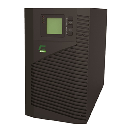
MISSION 1K●2K●3K SINGLE PHASE 2. PRODUCT INTRODUCTION 2.1 The appearance of the product Fig. 1 Front Panel view Fig. 2 1KVA Rear Panel view Fig. 3 2KVA Rear Panel view Fig. 4 3KVA Rear Panel view Rev. 02 – 19 March 2015... -
Page 5: The Principle Of The Product
MISSION 1K●2K●3K SINGLE PHASE 2.2 The principle of the product Fig 5 UPS Principle Diagram 1. Input filter: Complete filtering the input AC utility power to provide the clean power for UPS. 2. AC/DC converter: Convert the filtered AC mains to DC and boost the DC for DC/AC inverter. 3. -
Page 6: Installation
MISSION 1K●2K●3K SINGLE PHASE 3. INSTALLATION 3.1 Unpacking and inspection Unpacking the box and check the UPS. If damaged or some parts missing, don’t start the machine and inform your supplier. Check the box content (please consult Box Content Table). Check if the UPS is that you wanted to purchase. -
Page 7: Long Backup External Battery Connection
MISSION 1K●2K●3K SINGLE PHASE 3.5 Long backup external battery connection Fig 8 Battery connection Warning: ★ Before installing battery, make sure that UPS and breaker are all turned off. Remove all your metallic adornment such as finger ring, watch, and so on before connecting battery. ★... -
Page 8: Panel Display,Operation And Running
MISSION 1K●2K●3K SINGLE PHASE 4. PANEL DISPLAY, OPERATION AND RUNNING The operation is simple, operators only need to read the manual and follow the operation instructions listed in this manual without any special training. 4.1 Faceplate display illumination 4.1.1 Keys function Fig. - Page 9 MISSION 1K●2K●3K SINGLE PHASE 4.1.2 The function of LED indicators Warning red LED is on: UPS is fault. For example: Overload beyond the allowed time, inverter fault, BUS fault, over temperature fault etc. Bypass yellow LED is on: UPS is alarming. For example: Bypass mode supply power and etc. Battery yellow LED is on: UPS is alarming.
-
Page 10: Operation
MISSION 1K●2K●3K SINGLE PHASE Fan-status graphics section: display if the fan works normally. When the fan works normally, it will show the dynamic fan blades rotating; when the fan works abnormally, the icon will keep on flashing with the warning. Charger-status graphics section: display the status of the charger. -
Page 11: Parameter Setting
MISSION 1K●2K●3K SINGLE PHASE When turning off the UPS, it will do self-testing firstly. LED light and go out circularly and orderly until there is no display on the panel. 4.2.3 UPS self-test/mute test operation. When UPS is in line mode, press and hold the self-test/mute key for more than 1 second, LEDs light and go out circularly and orderly. - Page 12 MISSION 1K●2K●3K SINGLE PHASE 4.3.2 Output on bypass mode setting (bPS) Enter the setting interface. Press and hold the function setting key for more than 2 seconds, then come to setting interface, Press and hold the function setting key for more than half a second (less than 2 seconds), select the function setting, choose the auto battery test setting interface, at the moment, the letters “ABT”...
- Page 13 MISSION 1K●2K●3K SINGLE PHASE 4. Exit the configuration interface. Press and hold the button for more than 2 seconds to exit this configuration interface to return to the main interface. Note: When configuring the output voltage, the load should be off or disconnected from the UPS. 4.3.4 Number and type of battery selection function (bAt) 1.
- Page 14 MISSION 1K●2K●3K SINGLE PHASE 4.3.6 Battery discharge time setting function (tod) To enter the configuration interface, press and hold the configuration function key for more than 2 seconds, then access the Configuration Interface. Press the key until you reach the "tod" menu (6), the word "tod"...
- Page 15 MISSION 1K●2K●3K SINGLE PHASE Confirm the auto battery test setting interface. After selecting ON or OFF, press and hold the function setting key for more than half a second (less than 2 seconds), Now, the ABT setting function is completed and the “ON” or “OFF” below the “ABT” will light without flash. Exit from the setting interface.
- Page 16 MISSION 1K●2K●3K SINGLE PHASE second (less than 2 seconds) the selection is confirmed. Now, the EPO function configuration is completed and "" - P "or" + P "under" EPO "will remain fixed. Exit the configuration interface. Press and hold the configuration function key for more than 2 seconds to exit this configuration interface and return to the main interface.
-
Page 17: Parameters Inquiring
MISSION 1K●2K●3K SINGLE PHASE Exit the configuration interface. Press and hold the button for more than 2 seconds to exit this configuration interface to return to the main interface. IPF: The output frequency at the Ups is the same as that of the Ups input voltage. (inactive converter) 50.0Hz: the output frequency at the Ups is set at 50Hz, regardless of the input frequency at the Ups input. -
Page 18: Run Mode
MISSION 1K●2K●3K SINGLE PHASE Input: Display the voltage and frequency of the input. As the following graphics shows: the input voltage is 210V, input frequency is 49.8Hz. Battery: Display the voltage and capacity of the battery (determined by type). As the following graphics shows: the battery voltage is 28V, the capacity of battery is 100% (the capacity of battery is approximately reckoned according to the battery voltage). - Page 19 MISSION 1K●2K●3K SINGLE PHASE Bypass yellow LED is on, the buzzer beeps once every 2 minutes. The warning red LED is on when beeping, LCD displays are according to the exact load and battery capacity. Turn to bypass mode under the following two conditions: Turn off the UPS in line mode while start the bypass output.
-
Page 20: Maintenance
MISSION 1K●2K●3K SINGLE PHASE Fault mode (LCD interface on which the fault code display) When UPS has fault. The warning LED is on and the buzzer beeps. UPS will turn to fault mode. UPS cuts off the output and LCD display fault codes. At the moment, you can press the mute key to make the buzzer stop beeping temporarily to wait for maintenance. -
Page 21: Led Indication And Warning Table
MISSION 1K●2K●3K SINGLE PHASE 6.1 LED indication and warning table Appendix 1: Fault codes FAULT CODE FAULT CAUSATION 00-19 Bus Fault 20-39 Inverter Fault 40-44 Over Heat 45-49 Output short circuit 50-54 Overload 55-59 Output Relay Fault 60-64 Input NTC Fault 65-69 Auxiliary Power Fault 70-74... -
Page 22: Troubleshooting
MISSION 1K●2K●3K SINGLE PHASE mode seconds loads Once every 2 Check if the fan is blocked by ▲ ▲ ▲ ★ Fan fault (fan icon flash) seconds object. If display fault code and icon lights, contact for ● Fault mode Long beeps maintenance when you can’t deal with it by yourself. -
Page 23: Emc Standard/Safety Standard
SAFETY STANDARD NUMBER IEC62040-1 IEC62040-2 IEC61000-4-2 GB4943-5 IEC61000-4-3 IEC61000-4-4 IEC61000-4-5 6.4 PRODUCT PERFORMANCE MODEL MISSION 1000 MISSION 2000 MISSION 3000 RATED CAPACITY (VA/W) 1000VA / 800W 2000VA / 1600W 3000VA / 2400W Input Single phase and earthing Voltage range 115±5VAC - 295±5VAC... - Page 24 Full load ≥4min (only refers to standard UPS), As for long backup UPS, Backup time the backup time is determined by the capacity of battery. Charge current (A) ◆ Work Environment MISSION 1000 MISSION 2000 MISSION 3000 MODEL 0°C ~ 40°C Temperature 0~95% non condensing...
-
Page 25: Communication Interface
MISSION 1K●2K●3K SINGLE PHASE 6.5 COMMUNICATION INTERFACE 6.5.1 RS232 communication interface This UPS provides a standard DB9 communication interface on its rear panel, the definition of the pins is as following: DEFINITION 1-4-6-7-8-9 Not used 6.5.2 RS232 cable specifications When connecting the UPS with PC by RS232 cable, it needs to use the standard RS232 cable, the detailed cable No. - Page 26 MISSION 1K●2K●3K SINGLE PHASE 6.5.4 Emergency Power Off (EPO) The EPO function is used to shutdown the Ups by remote. This function, for example, can be used to turn off the load connected to the UPS by means of a thermal relay in case of over temperature in a room. When the EPO is activated, the UPS immediately switches off the output by disconnecting power from all the loads connected, the Ups remain alarmed by displaying the "EPO ON"...
Need help?
Do you have a question about the MISSION 1000 and is the answer not in the manual?
Questions and answers