
Summary of Contents for Generac Mobile Products MLT6SK
- Page 1 LIGHT TOWER MLT6SM • MLT6SK • MLT8SK 00749 OPERATING MANUAL Parts manuals available online at www.generacmobile.com 17973 G 07/15...
- Page 2 WARNING CALIFORNIA PROPOSITION 65 WARNING: Diesel engine exhaust and some of its constituents are known to the state of California to cause cancer, birth defects, and other reproductive harm. WARNING CALIFORNIA PROPOSITION 65 WARNING: This product contains or emits chemicals known to the state of California to cause cancer, birth defects, and other reproductive harm.
-
Page 3: Introduction
Generac Mobile Products, or can be found at www.generacmobile.com.The information contained in this manual was based on machines in production at the time of publication. Generac Mobile Products reserves the right to change any portion of this information without notice. - Page 4 This Page Intentionally Left Blank...
-
Page 5: Table Of Contents
Table of Contents Introduction ..........................iii Section 1 - Safety Safety Notes ............................1 Operating Safety..........................1 Engine Safety ............................. 2 Service Safety ............................ 3 Towing Safety............................. 3 Reporting Trailer Safety Defects ......................3 Safety Symbol Summary ........................5 Section 2 - General Information Specifications ............................. - Page 6 Section 6 - Wiring Diagrams Mast Light Connections ........................35 AC Wiring - MLT6SM, MLT6SK......................36 AC Wiring - MLT8SK ........................37 DC Wiring - Mitsubishi ........................38 DC Wiring - Kubota........................... 39 DC Wiring - Electric Winch ....................... 40 DC Wiring Option - Heated Fuel Filter - Mitsubishi................
-
Page 7: Section 1 - Safety
Section 1 - Safety SAFETY NOTES This is the safety alert symbol. It is used to alert you to potential personal injury hazards. Obey all safety messages that follow this symbol to avoid possible injury or death. This manual contains DANGERS, WARNINGS, CAUTIONS, NOTICES and NOTES which must be followed to prevent the possibility of improper service, damage to the equipment, personal injury or death. -
Page 8: Engine Safety
Safety • Bulbs become extremely hot during use. Allow bulb and light fixture to cool 10-15 minutes before handling. • NEVER raise, lower or turn the mast while the unit is operating. • ALWAYS extend the outriggers and level the unit before raising the mast. DO NOT retract the outriggers while the mast is up. -
Page 9: Service Safety
REPORTING TRAILER SAFETY DEFECTS If you believe your trailer has a defect which could cause a crash or could cause injury or death, you should immediately inform the National Highway Traffic Safety Administration (NHTSA) in addition to notifying Generac Mobile Products 17973 G... - Page 10 However, NHTSA cannot become involved in an individual problem between you, your dealer, or Generac Mobile Products LLC. To contact NHTSA, you may either call the Auto Safety Hotline toll-free at 1-888-327-4236 (TTY:1-800-424-9153), go to http://www.safercar.gov;...
-
Page 11: Safety Symbol Summary
Safety SAFETY SYMBOL SUMMARY This equipment has been supplied with numerous safety and operating decals. These decals provide important operating instructions and warn of dangers and hazards. Replace any missing or hard-to-read decals and use care when washing or cleaning the unit. Decal placement and part numbers can be found in the online parts manual at www.generacmobile.com. - Page 12 Safety This Page Intentionally Left Blank MLT6SM/K-8SK Operating Manual 17973 G...
-
Page 13: Section 2 - General Information
Section 2 - General Information SPECIFICATIONS GENERAC MODEL MLT6SM MLT6SK Engine Make/Brand................Mitsubishi ........Kubota Model ..................L3E-W461ML ......D1005-E3BG1-MGM-1 EPA Tier ..................4f ..........4f Horsepower - Prime hp (kW) ..........10.5 (7.8) .........11.7 (8.7) Horsepower - Standby hp (kW) ..........12.2 (9.1) .........13.1 (9.8) Operating Speed rpm .............1800 ........1800 Displacement in (L) ..............57.97 (0.95) ......61.08 (1.00) -
Page 14: General Information
General Information GENERAC MODEL MLT8SK Engine Make/Brand........................... Kubota Model ............................ D1105-E3BG EPA Tier ..........................4f Horsepower - Prime hp (kW) ....................13.5 (10.1) Horsepower - Standby hp (kW) ................... 15.4 (11.5) Operating Speed rpm ......................1800 Displacement in (L) ......................68.53 (1.12) Cylinders - qty ........................ -
Page 15: Unit Dimensions
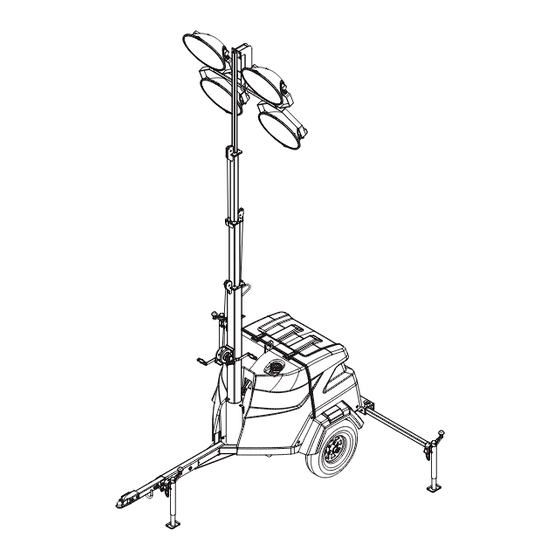
General Information Unit Dimensions 00751 Figure 1 - Unit Dimensions MLT6SM, MLT6SK, 118 in. (3 m) 101 in. (2.6m) 23 ft (7 m) 57 in. (1.45 m) 120.5 in. (3.1 m) MLT8SK Specifications are subject to change without notice. 17973 G... -
Page 16: Unit Serial Number Locations
VIN Tag Manufactured by Generac Mobile Products LLC (920) 361-4442 (800) 926-9768 TIRE AND LOADING INFORMATION DATE: 00/0000 MANUFACTURED BY/FABRIQUE PAR: Generac Mobile Products LLC Country of Origin Model Serial Number RENSEIGNEMENTS SUR LES COLD INF. PRESS./ GVWR/PNBV: 000KG (0000LBS) PNEUS ET LE CHARGEMENT PRESS. -
Page 17: Component Locations
General Information COMPONENT LOCATIONS 01742 Figure 3 - Component Locations - Front and Left Side 1. Outriggers 5. Tongue Jack 2. Rear Jack 6. Mast Rotation Knob 3. Fuel Fill 7. Winch 4. Tie Down Locations 8. Lights 17973 G MLT6SM/K-8SK Operating Manual... - Page 18 General Information 01743 Figure 4 - Component Locations - Rear and Right Side 1. Central lift point 5. Control box 2. Radiator access 6. Rear jack 3. Forklift pockets 7. Engine access 4. Tie down location MLT6SM/K-8SK Operating Manual 17973 G...
-
Page 19: Control Panel
15 SEC. MAX. STOP MAIN BREAKER 240V 00757 Figure 5 - Control Panel Component Locations - MLT6SM, MLT6SK 1. DC Breaker 6. 240V Twist-Lock Receptacle 2. AC Breaker 7. Engine Hour Meter 3. Light Switches 8. Main Circuit Breaker 4. Electric Winch Switch (Optional) 9. - Page 20 General Information DC CIRCUIT AC CIRCUIT BREAKER BREAKERS 120V 15 SEC. MAX. STOP MAIN BREAKER 240V 00758 Figure 6 - Control Panel Component Locations - MLT8SK 1. DC Breaker 6. 240V Twist-Lock Receptacle 2. AC Breakers 7. Engine Hour Meter 8.
-
Page 21: Prestart Checklist
General Information PRESTART CHECKLIST Before starting the unit, all items in the prestart checklist must be completed. Read and understand ALL safety sections at the beginning of this manual. Ensure all maintenance procedures are up to date. For more information, refer to “General Maintenance”... - Page 22 General Information This Page Intentionally Left Blank MLT6SM/K-8SK Operating Manual 17973 G...
-
Page 23: Section 3 - Operation
Section 3 - Operation LIGHT TOWER SET UP 1. For maximum light coverage, locate the unit at ground level or in a spot higher than the area being illuminated by the lamps. WARNING The mast extends up to 23 ft (7 m). Make sure the area above the unit is open and clear of overhead wires and obstructions. -
Page 24: Raising The Mast
Operation 6. Turn the jack handles clockwise to start leveling the trailer (E). Adjust all three jacks by turning their handles clockwise until they are firmly in contact with the ground and continue until the wheels are approximately 1 inch (2.5 cm) off the ground (F). 7. -
Page 25: Raising The Mast With Electric Winch Option
Operation 4. Rotate the mast by loosening the mast rotation knob at the bottom of the mast (C). Turn the mast until the lights face in the desired direction and then tighten the mast rotation knob to secure the mast in position. WARNING Never raise or lower the mast while the unit is operating. -
Page 26: Starting The Unit
Operation 4. Rotate the mast by loosening the mast rotation knob at the bottom of the mast (D). Turn the mast until the lights face in the desired direction and then tighten the mast rotation knob to secure the mast in position. WARNING Never raise or lower the mast while the unit is operating. -
Page 27: Derating For Altitude
Operation 1. Once the engine is up to temperature and running smoothly, switch the main circuit breaker (A) to the ON (I) position. DC CIRCUIT AC CIRCUIT BREAKER BREAKERS 120V 2. With the main circuit breaker on, switch each individual circuit breaker for the lights (B) to the ON (I) position, one at a time. -
Page 28: Control Panel Receptacles
Operation CONTROL PANEL RECEPTACLES The control panel is equipped with multiple receptacles 240V Twist-Lock 120V GFCI for running accessories or tools from the generator. Receptacle Receptacles Power is supplied to the receptacles any time the engine is running and the main circuit breaker is switched to the ON (I) position. -
Page 29: Lowering The Mast - Manual
Operation LOWERING THE MAST - MANUAL 1. Shut down the lights and engine, refer to “Shutting Down the Unit” on page 22. Allow the lights to cool 10-15 minutes before lowering the mast. 2. If the unit is going to be moved, it is recommended that the mast is turned so the lights face the rear of the unit. -
Page 30: Towing The Unit
Operation 1. Remove the power cables from the two terminals on the winch motor assembly (A). 2. Remove the two flange head screws (B) securing the winch motor assembly to the winch. Retain the screws for reassembly. 3. Carefully remove the motor assembly (C), making sure the two pieces do not separate. 4. -
Page 31: Lifting And Tie Down
Operation 10. Maximum recommended speed for highway towing is 45 mph (72 km/h). Recommended off-road towing speed is not to exceed 10 mph (16 km/h) or less, depending on the terrain. LIFTING AND TIE DOWN When lifting the unit, attach any slings, chains or hooks directly to the central lift point. The central lift point is located on top of the enclosure. - Page 32 Operation This Page Intentionally Left Blank MLT6SM/K-8SK Operating Manual 17973 G...
-
Page 33: Section 4 - Maintenance
Normal maintenance service and replacement of parts are the responsibility of the owner/operator and, as such, are not considered defects in materials or workmanship within the terms of the warranty. It is strongly recommended that the equipment be periodically checked by a Generac Mobile Products Authorized Dealer. DAILY WALK AROUND INSPECTION Look for conditions that could hinder performance or safety, such as (but not limited to) oil/coolant/fuel leakage, blocked vents, loose/missing hardware, and electrical connections. -
Page 34: Basic Maintenance Schedule - Mitsubishi Engine
Maintenance This Page Intentionally Left Blank MLT6SM/K-8SK Operating Manual 17973 G... -
Page 35: Basic Maintenance Schedule - Kubota Engine
If proper voltage is not achieved, perform capacitor check to determine if the capacitor or coil needs to be replaced. If problems persist, contact Generac Mobile Products Technical Service at 1-800-926-9768 for assistance. 17973 G MLT6SM/K-8SK Operating Manual...
Need help?
Do you have a question about the MLT6SK and is the answer not in the manual?
Questions and answers