Table of Contents

Related Manuals for Go Power GP-IC-2000


Summary of Contents for Go Power GP-IC-2000
-
Page 1: User Manual
INVERTER/CHARGER User Manual GP-IC-2000/GP-IC-3000 © 2017 Go Power! Worldwide Technical Support and Product Information gpelectric.com ® Go Power! 250 Bay St, Victoria, BC Canada V9A 3K5 Tel: 1.866.247.6527 79497_MANUAL_GP-IC-Series_RevC powered by... - Page 2 Combined with the numerous DC power systems Go Power! manufactures and sells, the IC Series allows you to enjoy the luxuries that electricity provides, with or without a campsite hookup. This manual will aid in the process of installing the Go Power! IC Se- ries Inverter/Charger.
-
Page 3: Table Of Contents
1. CONTENTS GENERAL INFORMATION ......................4 CAUTIONS .................................4 DISCLAIMERS ..............................7 IC SERIES KIT PARTS ............................7 2.3.1 PARTS CHECKLIST ..........................7 UNIT FEATURES ...............................8 UNIT DIMENSIONS ............................10 UNIT ACCESSORIES ............................11 INSTALLATION TOOLS AND MATERIALS ....................11 INSTALLATION .......................... 11 TYPICAL Inverter/Charger SYSTEM OVERVIEW ..................12 LOCATION AND ENVIRONMENTAL REQUIREMENTS ................ -
Page 4: General Information
2.GENERAL INFORMATION 2.1 CAUTIONS/WARNINGS This document contains important safety instructions for the products produced by Go Power! Read all instructions and cautionary markings on the product and on any accessories or additional equipment included in the installation. Failure to follow these instructions could result in severe shock or possible electrocution. Use extreme caution at all times to prevent accidents. - Page 5 Do not perform any servicing other than that specified in the WARNING! installation instructions unless qualified to do so, or have been Lethal Voltage instructed to do so by Go Power! Technical Support personnel. To avoid electric shock, disconnect the DC input and AC input of the inverter at least 5 minutes before performing any installation or maintenance. Do not tighten the AC and DC terminals or pull on the AC and DC wiring when the inverter is running.
- Page 6 If a battery must be removed, always remove the grounded terminal from the battery first. Make sure all devices are de-energized or disconnected to avoid causing a spark. Use the battery types recommended by Go Power!. Follow the battery manufacturer’s recommendations for installation and maintenance. Insulate batteries as appropriate against freezing temperatures. A discharged battery will freeze more easily than a charged one.
-
Page 7: Disclaimers
Go Power! will refuse requests for exchanges or returns, resulting from the purchase and installation of items which do not comply with local codes. To avoid such concerns Go Power! recommends installation by a professional electrician or RV technician. -
Page 8: Unit Features
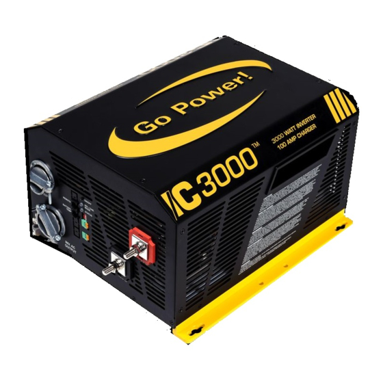
GENERAL INFORMATION 2.4 UNIT FEATURES Power Inverter/Charger Status LED Switches ON/OFF Switch Mode Intake Air Vents (and on right side) Positive (+) ON/OFF DC Terminal INV. / CHR. MODE REMOTE STATUS Negative (-) DC Terminal BATTERY AC INPUT TEMP Mounting AC Entry/Exit Flange Terminals... - Page 9 (Back side) Label Please note: Label shown is for a GP-IC-2000. Please refer to the label on your Inverter/Charger for accurate information. Dip Switches - Reserved for future use. Exhaust Air Vents - These cut-outs are used as ventilation openings. Air is drawn in through the front of the Inverter/ Charger and passes through to keep the electronics cool for optimum performance.
-
Page 10: Unit Dimensions
GENERAL INFORMATION 2.5 UNIT DIMENSIONS 13.6” (346mm) 4.9” 2” (51mm) 4.9” (124mm) (124mm) .28” .51” (7mm) (13mm) 12” (304mm) 12.6” (321mm) 14.9” (378mm) 13.7” (349mm) CAUTION: • TO PREVENT FIRE, DO NOT COVER OR OBSTRUCT VENTILATION OPENINGS. DO NOT MOUNT IN ZERO-CLEARANCE COMPARTMENT. -
Page 11: Unit Accessories
GENERAL INFORMATION 2.6 UNIT ACCESSORIES ® The IC Series Inverter/Charger has two accessories available: INVERTER SHORE POWER ON/OFF UNIT READINGS UNIT SETUP CHARGER REMOTE SETTINGS ON/OFF • IC 2000 series remote (not included). • Battery temperature sensor (included). ENTER / SET BACK IC 2000 Remote This remote control device can be used for monitoring the performance of the unit. -
Page 12: Installation
The following diagrams on pages 12-15 show how the GP-IC-2000 is typically installed in a mobile RV application. The diagrams show where the Inverter/Charger is installed and how the mobile power system can be integrated with a Go Power! RV Solar Kit (sold separately by Go Power;... - Page 13 INSTALLATION GP-IC-Remote Solar Controller Cable to Battery Bank Cable to IC Series AC Power OUTPUT - to RV appliances AC Power INPUT - from Shore Power/Generator (Fuses/Breakers not shown) IC Series IC Series Inverter/Charger Inverter/Charger Cables to/from Battery Bank Cables From Battery Bank Solar Charge Controller gpelectric.com | [page 13]...
- Page 14 AC Transfer Switch Refrigerator Vent Cover Cable Entry Plate Main Pane Solar Charge Controller Earth Ground (RV, Boat Ground) Fuse Battery Temperature Sensor To Battery Bank To Battery Bank Typical RV Solar Kit (sold separately by Go Power) [page 14] | gpelectric.com...
- Page 15 INSTALLATION Generator Power 120/240 VAC Remote Control (Optional) 120 VAC 240 VAC (cabin install) 120 VAC Sub Panel IC Series Inverter/Charger DC Panel Battery Disconnect Switch (not required if circuit breaker is used) Fuse or Circuit Breaker Battery Bank gpelectric.com | [page 15]...
-
Page 16: Location And Environmental Requirements
INSTALLATION 3.2 LOCATION AND ENVIRONMENTAL REQUIREMENTS The IC Series Inverter/Charger must be installed in a location that meets the following requirements: 1. TEMPERATURE Make sure the Inverter/Charger is installed in a location where the normal air temperature is between 0 °C and 50 °C. The cooler the better within this range. -
Page 17: Mounting The Inverter/Charger
OUTPUT The GP-IC-2000 weighs: 39 lbs (17.6kg). The GP-IC-000 weighs: 39 lbs (17.6kg). Take the necessary precautions required whilst lifting, moving and installing the unit. It is recommended to use two people whilst mounting the unit. All mounting surfaces and hardware must be capable of supporting at least twice the weight of the Inverter/Charger. -
Page 18: General Wiring Specifications
INSTALLATION 3.4 GENERAL WIRING SPECIFICATIONS The following sections detail how the IC Series Inverter/Charger should be wired. Before starting any wiring, read and understand these instructions. Wiring should meet all local codes and standards and be performed by qualified personnel such as a licensed electrician. -
Page 19: Dc Wiring
INSTALLATION Main Panel 3.5 DC WIRING The cables linking the Inverter/Charger to the battery bank are the DC cables. These cables handle the Direct Current power used to charge the batteries (Charging Mode) and power the main appliances (Inverter Mode). It is important to select the correct wire size and to provide adequate over-current protection between the Inverter/Charger and battery bank. -
Page 20: Dc Wire Sizing
If you install a fuse for overcurrent protection, then a separate disconnect switch will need to be installed. 3.5.3 PREPARING THE DC CABLES Go Power! supplies 2 ring lugs with the IC Series, which can be used for the Inverter/Charger end of the DC Cables. Source the correct ring terminals for the batteries you are using. -
Page 21: Battery Temperature Sensor
INSTALLATION DO NOT INSTALL ANYTHING BETWEEN RING LUG and DC TERMINAL Split Washer Washer Battery Temperature Sensor Battery Cable (with ring lug) Battery Post (Negative Terminal) Inverter/Charger DC Terminal Battery Cable (with ring lug) M8mm Washer M8mm Split Washer M8mm Nut DO NOT INSTALL ANYTHING BETWEEN RING LUG and BATTERY POST... -
Page 22: Wiring The Inverter/Charger To The Battery Bank
DC Positive and Negative Wires • Connect the negative cable from the battery bank negative terminal to the Inverter/Charger’s negative terminal. Mount the DC circuit breaker or fuse assembly and leave open (no power to the GP-IC-2000). Connect the positive 120 VAC Sub Panel cables from the circuit breaker/fuse to the battery bank and to the Inverter/Chargers positive terminal. -
Page 23: Battery Layouts
INSTALLATION 3.5.7 BATTERY BANK CONFIGURATIONS 12 VDC 12 VDC (400 AH) (600 AH) 12 VDC 12 VDC 12 VDC (400 AH) 12 VDC (600 AH) (400 AH) (600 AH) 12 VDC 12 VDC (100 AH) 12 VDC 12 VDC (200 AH) 12 VDC 12 VDC 12 VDC... -
Page 24: Dc Grounding
INSTALLATION 3.5.8 DC GROUNDING To protect against electrical shock hazards the IC Series metal chassis must be connected to the DC grounding system. The DC grounding system is sometimes referred to as the earth ground or another designated ground. For example, on an RV, the metal frame of the RV is designated as the negative DC ground/RV ground. - Page 25 INSTALLATION The AC cables link the Inverter/Charger to the main panel and the sub paneL. These cables handle the incoming alternating current (AC) utility or generator power which can be passed through the Inverter/Charger to directly power the main appliances (pass-through mode) and/or used to charge the batteries (charging mode).
-
Page 26: Ac Power Sources
3.6.3 GFCI (GROUND FAULT CIRCUIT INTERRUPTION) OUTLETS Compliance with UL standards requires that Go Power! test and recommend specific GFCIs for use on the AC output of the GP-IC-2000. GFCIs shall be installed in the AC output wiring system to protect all branch circuits. A GFCI is a device that de–energizes a circuit when a current exceeds a specified value that is less than that required to open the circuit breaker. GFCIs are intended to protect people from electric shocks and are usually required in wet or damp locations. -
Page 27: Ac Terminal Block Connections
INSTALLATION AC cover plate removed Phillips screw boss x3 Terminal label ACN-IN ACN-IN AC terminal block OUT1 OUT1 OUT2 OUT2 ACN-OUT ACN-OUT AC ground IN (from main panel) size : 55x36.5mm AC ground OUT (to sub panel) 3.6.4 AC TERMINAL BLOCK CONNECTIONS The IC Series has a six-pole AC terminal block and two AC ground terminals to connect the Inverter/Charger’s AC input and output wiring. -
Page 28: Ac Cable Connections
INSTALLATION 3.6.5 AC CONDUCTOR WIRING Make sure the IC Series is fully disconnected from the battery bank and no AC power is connected to the Inverter/Charger before commencing any AC wiring connections. AC INPUTS WIRING (50A Dual IN, Dual Out Configuration) • Remove the AC cover plate. • Route the wires: IN1 (Hot1), IN2 (Hot2), ACN-IN (neutral), and Ground from the main panel through the AC Input strain relief clamp. - Page 29 INSTALLATION AC GROUND WIRING • Connect the ground (Green) wire from the main panel to the AC Ground IN terminal. Tighten the terminal securely. • Connect the ground (Green) wire from the sub panel to the AC Ground OUT terminal. Tighten the terminal securely. Note: The Ground terminals are lugs and they are not labelled within the compartment.
-
Page 30: Ac Wiring 1 - Single Phase, ≤30A Service, Single In/Single Out
INSTALLATION 3.6.6 AC WIRING 1 - Single Phase, ≤30A Service, Single IN/Single OUT Single Phase - ≤30 Amp Service 120 VAC ≤30 Amps - 120VAC AC Power Source Hot1 Only Shore Power Generator Power 120 VAC 120 VAC Maximum Input Breaker (Single Pole Breaker) required... -
Page 31: Ac Wiring 2 - Single Phase, 30A> Service, Single In /Single Out
INSTALLATION 3.6.7 AC WIRING 2 - Single Phase, 30A> Service, Single IN /Single OUT Single Phase - 30> Amp Service 120 VAC ≤ 25 Amps a Leg AC Power Source Shore Power Generator Power 120 VAC 120 VAC Maximum Input Breaker (Single Pole Breaker) required... -
Page 32: Ac Wiring 3 - Split Phase, 50A Service, Dual In, Dual Out, Option 1
3.6.8 AC WIRING 3 - Split Phase, 50A Service, Dual IN, Dual OUT, Option 1 Split Phase - ≤50 Amp Service Install Option 1 120 / 240 VAC AC Power Source 50 Amps per 120 VAC leg. Hot 1 + Hot 2. Shore Power Generator Power 120/240 VAC... -
Page 33: Ac Wiring 4 - Split Phase, 50A Service, Dual In, Dual Out, Option 2
AC Power Source 50 Amps per 120 VAC leg. Hot 1 + Hot 2. Shore Power Generator Power 120/240 VAC 120/240 VAC CB1: 50A (located within the GP-IC-2000) Maximum Input Breaker CB2: 50A External Transfer Switch Switch (located within the GP-IC-2000) -
Page 34: Grounding The Inverter - Ac Grounding
Minimum #8 AWG Main Panel Wire OUT 2 (Input & Output) Size AC Live to sub panel Hot 1 (Black) Neutral Bus Bar AC Ground INSTALLATION ACN-OUT AC Ground to sub panel AC Neutral to sub panel Ground Bus Bar Maximum 6000W Inverter... -
Page 35: Disabling The Neutral To Chassis Ground Connection
Sub Panel Notes: Ground Bus Bar Neutral Bus Bar Notes: * All previo INSTALLATION * All previous converter/charger wiring must be disconnected from the breaker pan breaker panel. The IC Series is now used for battery bank charging. 3.6.11 DISABLING THE NEUTRAL TO CHASSIS GROUND CONNECTION The IC Series Inverter/Charger has the automatic neutral to ground switching feature enabled as a factory default setting. -
Page 36: Grounding On Boats
INSTALLATION 3.6.12 GROUNDING ON BOATS If you are installing the IC Series Inverter/Charger on a boat there are some specific guidelines/standards to follow. The Inverter/ Charger must be installed adhering to the standards of the ABYC (American Boat and Yacht Council). Some guidelines are out- lined below but these notes do not replace the full guidelines detailed in the ABYC standard. Always install the Inverter/Charger using the ABYC standard as the primary reference. -
Page 37: Final Inspection
INSTALLATION 3.7 FINAL INSPECTION Verify all cables/conduit runs are secured with zip ties or other non-conductive cable clamps to prevent damage from vibration. Ensure all cables that pass-through walls, bulkheads, or any other openings are protected against abrasion by using strain reliefs and/or grommets. -
Page 38: Operation
The AC load required to switch the Inverter ON is set to 5W as a factory default value. The search feature can be turned OFF and can be adjusted between 5 and 50W—to adjust these values the GP-IC-Remote must be used (this can be purchased separately from Go Power!). [page 38] | gpelectric.com... - Page 39 ABSORPTION FINAL (FLOAT) Battery Charging Current Time Equalization Charging: The EQ charging is used to stir up stratified electrolyte and to reverse any battery plate sulfation that may have occurred. The EQ charging mode can only be used with the GP-IC-Remote, sold separately by Go Power!. BATTERY CHARGING SET POINTS LED Status Flooded AGM 1 AGM 2...
-
Page 40: Ac Power Pass-Through Mode
OPERATION 4.2 AC POWER PASS-THROUGH MODE In AC power pass-through mode: • Shore power (utility or generator) is connected. The power required by the appliances (fridge, TV, charger) is 3600W (30AAC x 120VAC) - • • Shore power is powering all the appliances (3600W) - •... -
Page 41: Charging Mode
OPERATION 4.3 CHARGING MODE In charging mode: • Shore power (utility or generator) is connected and supplying 15AAC (1800W: 15AAC x 120VAC) - • No power is required by the appliances (fridge, TV, charger). • Batteries are being charged up to 100 Amps (with the 2000W) or 125 AMPs (with the 3000W) DC per hour - Utility Power Generator Power 120/240 VAC... -
Page 42: Power Sharing Mode
3600W OPERATION Main Panel 4.4 POWER SHARING MODE 1 In power sharing mode: • The power required by the appliances (fridge, TV, charger) is 4200W (35AAC x 120VAC) - AC Power Pass Through Mode • Shore power (Utility or Generator) is connected and supplying 6000W (50AAC x 120VAC) - * IC-2000 operates in AC Pass Through Mode •... -
Page 43: Generator Mode
OPERATION Main Panel 4.5 POWER SHARING MODE 2 In generator mode: • The power required by the appliances (fridge, TV, outlets) is 3600W (30AAC x 120VAC) - Inverting Mode Battery Discharging • Shore power (utility or generator) is connected and supplying 2400W (20AAC x 120VAC) - Battery Dis - Charging (1) 2000W of load power required (fridge, air conditioner, etc) ≈186 Amps DC / hour... -
Page 44: Inverting Mode
OPERATION 4.6 INVERTING MODE In inverting mode: • The load power required by the appliances (fridge, TV, charger) is 2000W (16.7AAC x 120VAC) - The inverter supplies the 2000W or 3000W (186 ADC x 12VDC x 0.9) of AC power required to power the •... -
Page 45: Battery Temperature Sensor Operation
2 Hours These settings are only adjustable with the GP-ICR-50 remote, which can be purchased separately from Go Power!. For detailed information on these settings please refer to the remote control manual. The remote also displays the real time Inverter/Charger’s operating status and allows the user to run the equalize charging profile on the battery bank. -
Page 46: Ic Series Fault Conditions
OPERATION 4.9 IC SERIES FAULT CONDITIONS The IC Series is protected against fault conditions and in normal use it will be rare to see any. If a fault condition does occur, the Inverter/Charger will shut down as a safety measure to protect itself, the battery bank, and the AC loads. The following fault conditions could be the cause of Inverter/Charger shut down: LOW BATTERY - The IC Series will shut off whenever the battery bank voltage falls to the Low Battery Cut Out (LBCO) level to protect the batteries from being over-discharged. When the Inverter/Charger has reached the LBCO and turned off, the unit will... - Page 47 Unit is in search mode, which means load is Inverter/Charger to full output power, or turn off too small for search mode circuit detection. Inverter LED is search function with the GP-IC-2000 remote. Loose or corroded battery cables. Clean and tighten all cables. Low output or Low batteries.
-
Page 48: Specifications
5. SPECIFICATIONS Electrical Specification Item GP-IC-2000 Nominal Voltage 12 VDC Absolute Max. DC Input 25 VDC HBCO/HBCI 17 VDC ±0.3V LBCO/LBCI 9.0 VDC ±0.3V Input Voltage Range 9 - 17 VDC ±0.3V Input Input Over-Voltage Protection 16.5 - 17 VDC Input Under-Voltage Protection 9 - 10.5 VDC... - Page 49 SPECIFICATIONS Electrical Specification Item GP-IC-3000 Nominal Voltage 12 VDC Absolute Max. DC Input 25 VDC HBCO/HBCI 17 VDC ±0.3V LBCO/LBCI 9.0 VDC ±0.3V Input Voltage Range 9 - 17 VDC ±0.3V Input Input Over-Voltage Protection 16.5 - 17 VDC Input Under-Voltage Protection 9 - 10.5 VDC Max DC Input Current 400 ADC...
-
Page 50: Important Safety Instructions
6. IMPORTANT SAFETY INSTRUCTIONS SAVE THESE INTRUCTIONS: This manual contains important safety and operating procedures. The IC Series Inverter/Chargers are Marine UL listed, and can be used in marine applications. Below are important safety and operating instructions for using the IC Series in marine applications. CAUTION! Personal Injury. -
Page 51: Warranty Return Procedure
An RMA number (Return Materials Authorization number) from Go Power! Customer Service is required prior to returning any Go Power! products. Go Power! reserves the right to refuse any items sent to Go Power! without an associated RMA number. To obtain an RMA number, please contact customersupport@gpelectric.com... -
Page 52: Product End Of Life Information - Recycling
A Phillips screwdriver is required to disassemble the Inverter/Charger. Note: The IC Series should only be disassembled at the end of its service life. Go Power! provides no spare parts for the Inverter/Charger. Remove the screws holding the outer case to the base plate. The plastic handles can be removed from the outer case by pushing them out from the inside. - Page 53 END OF LIFE - RECYCLING INFORMATION Remove the screws holding PCB #2. PCB #2 Recycling (small electronics) Remove the screws holding the transformer. Transformer (Copper) Recycling (small electronics) Metals Copper Remove the screws holding the Remove the screws holding PCB The Inverter/Charger has been fans.
- Page 54 © 2017 Go Power! Worldwide Technical Support and Product Information gpelectric.com ® Go Power! 250 Bay St, Victoria, BC Canada V9A 3K5 Tel: 1.866.247.6527 79497_MANUAL_GP-IC-Series_RevC powered by...
Need help?
Do you have a question about the GP-IC-2000 and is the answer not in the manual?
Questions and answers