Table of Contents
Advertisement
Advertisement
Table of Contents
Troubleshooting

Subscribe to Our Youtube Channel
Related Manuals for Go Power GP-PWM-25


Summary of Contents for Go Power GP-PWM-25
- Page 1 Go Power! Manual GP-PWM-25 Regulator...
- Page 2 Owner’s Manual | GP-PWM-25 Regulator © 2009 Carmanah Technologies Corporation Last revised July 2009...
-
Page 3: Table Of Contents
CONTENTS Installation Overview .................4 Introduction ....................4 Specifications....................4 Warnings.....................5 Tools and Materials Needed..............5 Choosing a Location .................6 Installation Instructions................6 Operating Instructions................7 Before You Read Troubleshooting............10 Troubleshooting Problems ..............11 Problems with the Display...............11 Problems with Voltage ................11 Problems with Current ................12 Limited Warranty..................13 General Warranty Issues ..............13 Repair and Return Information.............14 10.0 Glossary…………………………………………………………………………15... -
Page 4: Installation Overview
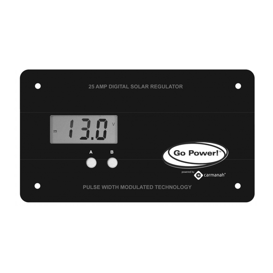
100% state of charge, the Regulator prevents overcharging by limiting the current flowing into the batteries from your solar array. The GP-PWM-25 is an automatic selecting 12 or 24 volt flush mounted photovoltaic (PV) charge controller rated for a continuous solar current input of 25 amps. The GP-PWM-25 uses pulse width modulation technology and a unique four stage charging system and optional equalize setting to charge and protect your battery bank. -
Page 5: Warnings
Torque wrench (optional) Electrical Tape If the GP-PWM-25 Regulator was purchased with a Go Power! RV Solar Power Kit then UV resistant wire is included. For instructions regarding the Go Power! RV Solar Power Kit installation, please refer to the Installation Guide provided with the Kit. -
Page 6: Choosing A Location
Owner’s Manual | GP-PWM-25 Regulator 4.0 Choosing a Location The GP-PWM-25 is designed to be mounted flush against a wall, out of the way but easily visible. The GP-PWM-25 should be: • mounted as close to the battery as possible. -
Page 7: Operating Instructions
NOTE: If the battery voltage is below 6 Volts the GP- PWM-25 will not function. Sleep Mode: The GP-PWM-25 will go into “sleep mode” after 30 minutes of no user activity (pushing the buttons). In sleep mode the GP-PWM-25 turns it’s display off to conserve power. To bring the regulator out of sleep mode, simply press the A Button and the display will reappear. - Page 8 Confirm the Battery Type / Charging Profile selection by pressing the A Button. Depending on the battery voltage when the GP-PWM-25 Power Up occurs, the GP-PWM-25 may do a Boost Charge or quickly go into Float Charge. The Charging Profile selected will commence the following day after a Power Up.
- Page 9 The GP-PWM-25 will begin to limit the current as the battery reaches a full charge. Icons Displayed: Sun, Battery, Current Symbol (A) Non volatile memory: Any settings made on the GP-PWM-25 will be saved even when the power has been disconnected from the regulator. Errors...
-
Page 10: Before You Read Troubleshooting
Ensure they are in a well ventilated space. My voltmeter shows a different reading than the GP-PWM-25 display The meter value on the GP-PWM-25 display is an approximate reading intended for indication purposes only. There is an approximate 0.1 volt inherent error present that may be accentuated when compared with readings from another voltmeter. -
Page 11: Troubleshooting Problems
Owner’s Manual | GP-PWM-25 Regulator Troubleshooting Problems How to read this section Troubleshooting Problems is split into three sub-sections, grouped by symptoms involving key components. Components considered irrelevant in a diagnosis are denoted ‘Not Applicable’ (N/A). A multimeter or voltmeter may be required for some procedures listed. -
Page 12: Problems With Current
Owner’s Manual | GP-PWM-25 Regulator 8.3 Problems with Current Current Reading: 0 A Time of Day: Daytime, clear sunny skies Possible Cause: (1) Current is being limited below 1 Amp as per normal operation. (2) Poor connection between solar array and regulator How to tell: (1) The State of Charge (SOC) screen is close to 100% and the Sun and Battery icon are present with an arrow between. -
Page 13: Limited Warranty
Owner’s Manual | GP-PWM-25 Regulator 9.0 Limited Warranty 1. Carmanah warrants the GP-PWM-25 for a period of five (5) years from the date of shipment from its factory. This warranty is valid against defects in materials and workmanship for the five (5) year warranty period. It is not valid against defects resulting from, but not limited to: •... -
Page 14: Repair And Return Information
Owner’s Manual | GP-PWM-25 Regulator 6. This warranty supersedes all other warranties and may only be modified by statement in writing, signed by Carmanah. 7. Warranty terms effective as of January, 2009. 9.2 Repair and Return Information To return items: 1. -
Page 15: Glossary
Owner’s Manual | GP-PWM-25 Regulator 10.0 Glossary Ampere: A unit of electrical current. Designates the number of electrons flowing per second through a conductive material. Array: One or more photovoltaic (PV) modules electrically connected to produce a single electrical output. -
Page 16: Installation Template
Owner’s Manual | GP-PWM-25 Regulator 11.0 Installation Template © 2009 Carmanah Technologies Corporation Last revised July 2009... -
Page 17: Wiring Diagram
Owner’s Manual | GP-PWM-25 Regulator Wiring Diagram 12.0 THE GP-PWM-25 IS BASED ON A 25 AMP MAX FOR THE SOLAR ARRAY TOTAL IMP OF THE SYSTEM. E.G. THREE MODULES IN PARALLEL WITH AN IMP OF 7 AMPS EACH EQUALS A TOTAL IMP OF 21 AMPS. - Page 18 © 2009 Carmanah Technologies Corporation carmanah.com Technical Support: info@gpelectric.com Toll Free (US and Canada): 1-800-667-6527 Worldwide: 1-250-652-5233 Toll Free Fax (US and Canada): 1-866-607-6527 Number: 57175_MAN_GP-PWM-25 Regulator_RevB-8.5x11 57175...
Need help?
Do you have a question about the GP-PWM-25 and is the answer not in the manual?
Questions and answers