
Related Manuals for Bosch EX49


Summary of Contents for Bosch EX49
-
Page 1: Installation Instructions
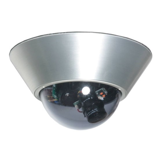
Precision Engineered Opto-Electronics™ INSTALLATION INSTRUCTIONS EX49 “No-Grip” High Impact Dome Camera MAN-49-00... - Page 2 IMPORTANT SAFETY INSTRUCTIONS Read these instructions. Keep this instruction. Heed all warnings. Follow all instructions. Do not use this apparatus near water. Clean only with dry cloth. Do not block any ventilation openings. Install in accordance with manufacturer instructions. Do not install near any heat sources such as radiators, heat registers, stoves or other apparatus (including amplifiers) that produce heat.
- Page 3 consult an electrician for replacement of the obsolete outlet. Protect the power cord from being walked on or pinched particularly at plugs, convenience receptacles, and the power where they exit from the apparatus. Only use attachments/accessories specified by the manufacturer. Use only with the cart, stand, tripod, bracket, or table specified by the manufacturer, or sold with the apparatus.
- Page 4 EU Directives covered by this declaration: 72/9/EC Low Voltage Directives 89/336/EEC Electromagnetic Compatibility Directive Bosch Security Systems, Inc. will not be responsible for injuries or damages resulting from the improper installation or use of any product sold by Bosch Security Systems, Inc their agents,...
- Page 5 PSU box. 3) Contact Bosch for further advice.
-
Page 6: Table Of Contents
INDEX – EX49 Page Description ............1 Unpacking ............2 Parts List ............2 Items Required for Installation ......2 Initial Preparations ..........3 Guidelines ............3 Section 1. Dome Removal .........4 Section 2. Input Power Connections....6 Section 3. Mounting – Camera Base ....9 Section 4. Lens: Directional, Focus, and “Auto-Iris”... -
Page 7: Description
A voltage regulator circuit allows for 12V dc or 24V ac operation, and a range in between, also providing protection from voltage surge, transient spikes, and reverse voltage. The EX49 is available in several models designed to meet specific needs. -
Page 8: Unpacking
Check the parts list and confirm all items have been located. Inspect the equipment thoroughly to ensure nothing was damaged in transit. Contact BOSCH Service Center if a problem is noted, see the rear page of this booklet for contact numbers. -
Page 9: Initial Preparations
GUIDELINES The installation of the EX49 camera is explained in Sections 1 to 5 listed below. It is important that these steps are followed in sequence Dome Removal Input Power Connections Mounting –... -
Page 10: Section 1. Dome Removal
1. DOME REMOVAL The camera dome and its retaining ring must be removed prior to mounting the camera or adjusting the lens direction. The set-screws in the retaining ring are not tightened in the factory and protrude by 1/8" (3mm) in order for the ring to be rotated. Refer to Figure 1 - 1 on page 5. - Page 11 Rotation Set Screws Retaining Ring Dome Camera Base FIGURE 1 – 1 Dome Removal...
-
Page 12: Section 2. Input Power Connections
Attention: External Video Cable Systems Must Be Properly Grounded In Accordance With The National Electrical Code, ANSI/NFPA 70. The EX49 Camera Unit is pre-connected with an electrically isolated power board (VRB) for 24V ac or 12V dc operation, with no change to the polarity of the wires. - Page 13 Power Power FIGURE 2 – 1 12VDC or 24VAC Electrically Isolated Power Board...
- Page 14 This view shows the location of the optional Heater Module for the Single Board Fixed Lens Cameras. Camera and Single Board Mounting Bracket VRB Module (reference only, not exactly as shown). Camera Heater From Power Input Board Terminal Block on VRB Module FIGURE 2 –...
-
Page 15: Section 3. Mounting - Camera Base
3. MOUNTING - CAMERA BASE Caution: The selected mounting location should not place the camera in a situation where its environmental specifications could be exceeded. See page 30. Ensure the selected location is protected from falling objects, accidental contact with moving objects, and unintentional interference from personnel. - Page 16 The mounting holes are configured for a single-gang electrical box or a round ceiling electrical box. The camera base can also be mounted to any flat surface. See the template on page 29. It would be advantageous if the power and video wires from the remote source could be routed into the electrical box at this time.
- Page 17 Use four (4) screws for double-gang boxes or two (2) screws for ceiling boxes. FIGURE 3 – 1 – 1 EX47 Camera Adaptor Plate Mounting...
- Page 18 FIGURE 3 – 1 – 2 EX47 Camera Base to Adaptor Plate Mounting...
- Page 19 FIGURE 3 – 1 – 3 EX49 Camera Base Mounting...
-
Page 20: Section 4. Lens: Directional, Focus, And "Auto-Iris" Adjustments
4. LENS: DIRECTIONAL, FOCUS, and “AUTO-IRIS” ADJUSTMENTS For optimum picture quality the camera lens must be as close as possible to the dome’s inside face, without touching. The lens and inside dome clearance as well as the camera’s directional adjustment can be achieved through the use of the PTT adjustment bracket attached to the housing base. - Page 21 Note: Gasket Back Cover - Some products have a paper backing on the gasket. Please remove it before installation. Mounting - It is recommended that the camera be mounted to a flat non-porous surface for best results. The mounting holes and the area around the mounting screws should be sealed with silicone to prevent water or moisture from entering into the unit.
- Page 22 FIGURE 4 – 1 Camera Lens Directional Alignment...
- Page 23 PTT Bracket PTT Locking Knob Base Adjustment Knobs (2) Lens Vertical Adjustment Tilt Adjustment Note: the optional camera heater board is not shown for reasons of clarity. Loosen the two adjustment knobs on the PTT bracket and tilt the lens to the desired viewing angle.
- Page 24 Base Camera Rotation PTT Bracket Linear Adjustment Locking Knob Loosen the locking knob, rotate the PTT and Camera/Lens assembly to the desired position, and re-tighten the knob. The Camera Assembly can also be moved along the linear axis by this method.
- Page 25 Camera Lens. Adjustable Disc for rotation Disc Rotation Camera Boards (dual) This adjustment is necessary in case the image on the monitor is not perpendicular. DO NOT touch the camera lens during this adjustment. Grip the camera boards between thumb and finger.
- Page 26 4.1 Vari Focal and “Auto-Iris” Control Adjustments Step 4.1.1 - Loosen the lens set-screws For focus/zoom adjustments. See Figure 4-5 on page 21. Step 4.1.2 - The set screw marked N ←→ ∞ is used for image focus. Step 4.1.3 - The set screw marked T←→ W is used for telephoto or wide- angle settings.
- Page 27 Loosen this set screw for Focus adjustment. Loosen this set screw for Telephoto (T) or Wide Angle (W) adjustment. FIGURE 4-5 Lens Focus Adjustment...
- Page 28 Vari Focal Lens Adjustments • Loosen the lens set screws for focus/zoom adjustments. • The setscrew marked N ←→ ∞ is used for image focus. • The setscrew marked T←→ W is used for telephoto or wide-angle settings. • Re-tighten the setscrews after focus adjustments have been completed.
- Page 29 Use a Neutral Density filter or Infra-Red Pass filter to cover the lens during focusing to simulate low light conditions on scene for correct 24-hour focusing. For camera with vari- focal lens, the camera should be focused with the lens iris fully opened to simulate the worst possible depth of field.
-
Page 30: Section 5. Camera Re-Assembly
5. CAMERA RE-ASSEMBLY Make sure all wires are properly connected and tightened into the terminal blocks, all holes are sealed against moisture penetration, and all mounting screws are tight. Step 5.1 - Check that the large “O” ring gasket in the camera base has not been dislodged or distorted. - Page 31 Camera Base Adhesive Dome Retaining Ring Set Screws Tighten FIGURE 5 – 1 Camera Re-Assembly The Camera/Lens and PTT Assemblies are not shown for clarity purposes.
-
Page 32: Section 6. Troubleshooting Guide
6. TROUBLESHOOTING GUIDE PROBLEM POSSIBLE LIKELY SOLUTION CAUSE No Video 1. Power Supply: -Connections…. Check input power connections at the cable leads. Check for loose wires. -Voltage Range... If connected to DC, check input voltage range of 10.5 – 40V. If connected to AC, check input voltage range of 12 –... - Page 33 If still no video, connect the camera directly to the monitor. Check the video signal. If okay, the problem is with the interconnections. If still no video, contact BOSCH Service Center. See rear page of this manual for contact information __________ ________________ _________________...
- Page 34 Poor Picture Snowy Noisy Power Check connections. Image Supply Relocate or replace (cont’d.) the power supply. Horizontal Ground Looping on Check the coax cable Scan Lines, video cable shield is not touching Rolling Up ground, e.g. at or Down couplings. Check video polarity.
-
Page 35: Section 7. Template - Mounting Holes
MOUNTING HOLE DIAGRAM... -
Page 36: Section 8. General Specifications
8. GENERAL SPECIFICATIONS TV System ..Color – NTSC (PAL optional) Monochrome – EIA (CCIR optional) Video Signal Output.... 1 V p-p, 75 Ohm Operational Range....-50°C to +50°C *with optional heater ..... -70°C to +50°C Humidity Range .....Up to 85% (relative) Power Supply (dc) ..... - Page 37 NOTE:...
- Page 38 NOTE:...
- Page 39 Phone: +65 6319 3450 Telephone+1 888-289-0096 Phone: + 31 40 2577 284 Fax: +65 6319 3499 +1 585-223-9180 Fax: +31 40 2577 330 apr.securitysystems@bosch.com Email: security.sales@us.bosch.com emea.securitysystems@bosch.com www.boschsecurity.com www.boschsecurity.us www.boschsecurity.com © Bosch Security Systems, Inc. 2009; Data subject to change without notice.
Need help?
Do you have a question about the EX49 and is the answer not in the manual?
Questions and answers