Table of Contents
Advertisement
Advertisement
Table of Contents

Related Manuals for Corsair AIR540


Summary of Contents for Corsair AIR540
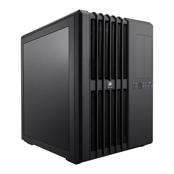
- Page 1 CARBIDE SERIES ® HIGH AIRFLOW MID-TOWER CASE INSTALLATION GUIDE...
- Page 2 PCI-E components without your drives or power supply getting in the way. Quieter Operation Carbide Series Air 540 includes 140mm Corsair Air Series AF140L intake and exhaust fans. The AF140L is based on the award-winning AF140 and provides great airflow performance at lower noise levels than typical case fans.
- Page 3 CARBIDE SERIES AIR 540 HIGH AIRFLOW MID-TOWER CASE ® Corsair AF140L (x3) fans included Top Dual 120mm/140mm fan mounts compatible with 240/280mm radiators Rear 120mm/140mm fan mounts compatible with 120/140mm radiators Front Triple 120mm/140mm fan mounts compatible with 240/280/360mm radiators USB 3.0 (x2) Headphone/Mic, Power/Reset...
- Page 4 CARBIDE SERIES AIR 540 HIGH AIRFLOW MID-TOWER CASE ® Built-in cable routing cutouts with grommets Tool-free optical drive bays (x2) Tool-free 3.5" hard drive caddy with 2.5" compatibility (x2) HDD/SDD Hot-swap bay (x2) Tool-Free expandable 2.5" SSD removable cage Eight expansion slots for GPUs Removable Front Magnetic low restriction dust filter...
- Page 5 Removing the side panels Installing the motherboard Install your motherboard’s I/O shield Unscrew thrumbscrews and remove, then pull side panels outward (see motherboard manual for guidance) Align motherboard with the stando s in the case NOTE: It is advised that both side panels are completely removed Secure with included screws ( MBD/HDD screws) and set aside when building your system to avoid accidental damages...
- Page 6 Installing the Power Supply (PSU) Installing the PCI-E/PCI Cards Remove thumbscrews and corresponding slot cover(s) Unscrew and remove PSU mounting bracket Install the add-on card & secure with thumbscrews Place the PSU on the bottom of the case with the fan side facing outwards Align holes &...
- Page 7 Installing 5.25" Drive/Devices (ODD) Remove the front panel 5.25" drive bay cover Insert ODD into drive bay until tool-free latch clicks securing the drive To remove drive, push tool-free tab to release...
- Page 8 Installing 3.5" HDD/ 2.5" SSD Remove Tool-free 3.5" HDD tray Insert HDD into HDD tray Align HDD holes with the tray pins to secure NOTE: Tool-free 3.5" HDD tray are also compatible with 2.5" SSD...
- Page 9 Installing 2.5" SSD into Tool-free expandable SSD cage Installing Hot-swap connectors Plug the Sata connector to the Sata power cable Place the SSD into the tool-free cage until you feel it secure Plug the Sata data cable to the motherboard Sata header To remove the SSD, pull tab to release...
- Page 10 Attach case fan cables to motherboard headers Installing front I/O connectors See motherboard manual for front panel header locations and pin-outs See motherboard manual for fan header locations USB 3.0 HDD LED POWER SW POWER LED – HD AUDIO RESET SW POWER LED +...
- Page 11 How to remove/install SSD Cage How to remove front magnetic dust filters Unscrew the thumbscrews from rear top dust filter To remove, push the tab down to release the SSD cage Pull the top dust filter back and upwards to remove Lift SSD cage up to remove Pull the front dust filter up and outwards to remove To install, align the SSD cage with holes and slide down until secure...
Need help?
Do you have a question about the AIR540 and is the answer not in the manual?
Questions and answers