
Related Manuals for AFL OFL280 FlexTester


Summary of Contents for AFL OFL280 FlexTester
- Page 1 OFL280 FlexTester User Guide ® www.AFLglobal.com or (800) 321-5298, (603) 528-7780...
-
Page 2: Table Of Contents
Light Source and Power Meter Settings ..........20 Trace Page Features ................22 Event Table Page Features ..............23 Summary Page Features ..............24 Information Page Features ..............24 © 2008-2011, AFL, all rights reserved. OFL2-28-1000 Revision 1E 2011-08-31 Specifications are subject to change without notice. - Page 3 Table of Contents Running OTDR Tests and Viewing Results ........25 To Start a Test ..................25 Test Viewer Pages Description ............25 Saving and Reviewing Test Results ..........26 File Manager System ................26 File Manager – Jobs Page ..............26 File Manager – Cables Page ...............27 Creating New Cables (folders) Using the Save As Page .......29 Selecting a Cable as the Current Cable (folder) ........29 Saving Test Results ................29...
-
Page 4: Safety Information
Safety Information WARNING! Use of procedures or adjustments other than those specified herein may result in hazardous radiation exposure. This is a CLASS I LASER 1310/1550 nm OTDR/OLS port output 1310/1490/1550 nm OTDR/OLS port 1310/1550/1625 nm OTDR/OLS port 1310/1550/1625 nm/Live Fiber filter/PON meter OTDR/OLS port This is a CLASS II LASER VFL port... -
Page 5: General Information
FlexTester and assumes that you have basic knowledge about testing fiber optic networks. The purpose of this user’s guide is to explain how to use and maintain your OFL280 FlexTester. Please check our web site at www.AFLglobal.com, NOYES Test and Inspection for updates to this manual, software updates, and additional application information. -
Page 6: Ofl280 Hardware Features
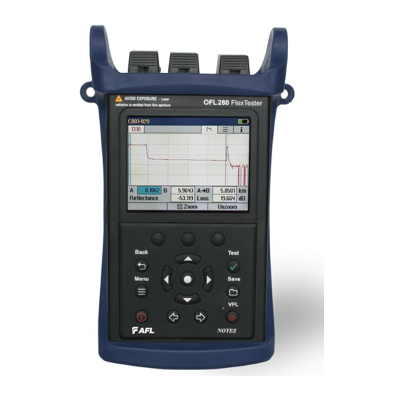
OFL280 Hardware Features Front Panel (Keys and Display) The OFL280 front panel contains keys, indicator, and a display. The use of the [Power], [Menu], [Test], [Back], [Save], and [VFL] keys are fixed. The use of the soft function keys and arrow keys depends on which menu or editor submenu is displayed. -
Page 7: Top Panel (Test Ports)
Top Panel (Test Ports) Red colored bar indicates Blue colored bar indicates the OTDR/OLS test port the VFL test port OPM test port - Input for the Silver bar - UPC ferrule standard optical power meter Green bar - APC ferrule OTDR OLS OPM port VFL port - This is a CLASS II LASER output. -
Page 8: Front Panel Keys
Front Panel Keys The use of each key is summarized in the table below. Key Symbol Key Name Key Function Power Press and hold (~1 second) to turn the OFL280 on or off. VFL laser Visual Fault Locator (red laser) ON - Press and hold (~1 second) LED will flash ON - Press and hold (~1 second) LED will be solid OFF - Press and hold (~1 second) LED should be OFF... -
Page 9: Ofl280 Models
OFL280 Models The OFL280 FlexTester is available in four models as indicated below: AFL No. WAVELENGTHS and added fea- notes tures OFL280-100 1310, 1550 nm Dual-wavelength OTDR/Loss test set for both point-to-point and PON applications OFL280-101 1310, 1550, 1625 nm... -
Page 10: Main Menu
Main Menu Main Menu - OFL280-103 model shown Time Main Menu tabs Page header Battery icon - < 10% Highlighted tab - Fully charged indicates the currently displayed Menu Page Press USB to transfer saved The currently results and highlighted Menu download software option upgrades (OTDR is... -
Page 11: Understanding Otdr Test Parameters
Understanding OTDR Test Parameters Parameter Description Range The [Range] parameter determines the distance range of the full (unzoomed) trace. It also determines the distance between data points in the trace: the longer the range, the wider the data point spacing. We recommend selecting the shortest distance range that is longer than the fiber under test. - Page 12 Pulse width Narrow pulse widths provide better resolution. That is, they may be used to detect events which are close together. However, narrower pulse widths inject less optical energy into the fiber-under-test, resulting in a noisier trace (lower dynamic range). If a narrow pulse width is used on a long fiber, the trace may reach the noise floor before the end of the fiber is reached.
-
Page 13: Fttx - In Service Test Mode Settings (Ofl280-103 Only)
FTTx – In Service Test Mode Settings (OFL280-103 only) In the FTTx – In Service mode (available only in the OFL280-103 model) the first page displays received FTTx PON power at 1490 and 1550 nm. On dark fibers users can test at 1310/1550 nm. On live fibers users can test only at 1625 nm. -
Page 14: Fttx - Pon Construction Test Mode Settings
FTTx - PON Construction Test Mode Settings In this test mode, the user may select the desired test wavelength(s) and set the [Range] and [PON] parameters. From the Mode menu, display the FTTx - PON Construction page. keys to highlight the desired test setup parameter to set. keys to set/change the highlighted parameter. -
Page 15: Real Time Test Mode Settings
Real Time Test Mode Settings In the Real Time test mode, the user may set the [Auto Setup] parameter to [Off] or [By Range]. • [Off]: Setting the [Auto Setup] parameter to [Off], allows the user to set the [Range], [Pulse], and [Resolution] parameters. -
Page 16: Event Thresholds: Fttx - In Service Mode
Event Threshold Settings Event threshold settings may be modified in FTTx - In Service, FTTx - PON Construction, Full Auto, and Expert test modes. Event Thresholds: FTTx – In Service mode In the FTTx - In Service test mode the [Event] parameter is set to [Auto] by default. 1. -
Page 17: Event Thresholds: Fttx - Pon Construction Mode
Event Thresholds: FTTx – PON Construction mode In FTTx – PON Construction mode, the [Events] parameter is set to [Auto] by default and may not be disabled. 1. From the FTTx - PON Construction test mode page, display the Event menu A using keys. -
Page 18: Event Thresholds: Expert Mode
Event Thresholds: Expert mode In Expert mode, the [Events] parameter may be set to [Auto] or [Off]. When set to [Auto], automatic event detection is enabled, applying user-set End Loss, Event Loss, and Event Reflectance thresholds. Thresholds are adjusted as follows: From the Expert test mode page, display the Event menu A using keys. -
Page 19: Cables Menu Settings
Cables Menu Settings Note: Launch and Receive cables are required to measure the insertion loss and reflectance of the near-end and far-end connectors respectively, on the fiber link being tested. See section titled “Recommended Accessories” for details and recommended launch and receive cable lengths. Launch Cable (Launch Cord) - A test cable used to connect an OTDR to the near end of the link under test. -
Page 20: Light Source And Power Meter Settings
Light Source and Power Meter Settings Light Source Operation After enabling the Light Source & Optical Power Meter test mode or turning the [Laser] option On, let the laser stabilize for approximately five minutes. 1. Use keys to highlight the desired light source setup parameter. 2. - Page 21 Wave ID Mode Feature Wave ID is a powerful feature which cuts multi-wavelength testing time in half and eliminates user setup errors. 1. When Wave ID is enabled in the Source, each wavelength is transmitted with a wavelength indicator. A Wave ID-compatible Power Meter will detect and synchronize its wavelength calibration factor to the transmitted wavelength, eliminating the need for the user at the Source fiber end from having to call the user at the Power Meter fiber end to tell him/her which wavelength is being sent.
-
Page 22: Trace Page Features
Trace Page Features The illustration below and table on the next page describe the Trace Page features (example trace below includes a launch and receive cable). Trace Page displays OTDR trace, A/B cursors, Event Table displays OTDR Loss, Distance, and max reflectance between event measurements A and B cursors Summary Page... -
Page 23: Event Table Page Features
Event Table Page Features Event Table is always generated if testing in the FTTx - In Service or FTTx - PON Construction test mode and optionally generated if testing in the Full Auto or Expert test mode. 1. In the FTTx - In Service and FTTx - PON Construction modes, [Events] are set to [Auto] by default. 2. -
Page 24: Summary Page Features
Summary Page Features Summary page displays: trace graph, fiber under test [Length] in user selected units, [Loss] and [ORL] in (dB) For multiple-wavelength tests, press to toggle the wavelength and display [Length], [Loss] and [ORL] test results for that wavelength Information Page Features The information page displays how the test was created. -
Page 25: Running Otdr Tests And Viewing Results
Running OTDR Tests and Viewing Results To Start a Test • Press the - Test key. Note: After an OTDR test is started, it may take several seconds for the first results to appear and depending on setup, tens of seconds or even several minutes for tests to complete. To Stop a Test • Press the - Test key. -
Page 26: Saving And Reviewing Test Results
Saving and Reviewing Test Results File Manager System The OFL280 File Manager system consists of four pages as follows: Page Name Description Jobs Lists the Jobs (folders) stored in the OFL280 internal memory. Use to open or delete the highlighted job folder. Cables Lists the Cables (folders) in the currently open Job folder. -
Page 27: File Manager - Cables Page
File Manager – Cables Page Depending on the prior settings, the File Manager may be displayed as [Jobs], [Cables], or [Traces] page. To display [Cables] page perform the following. • Press the [Files] soft key. • If the [Jobs] page is displayed, highlight the desired job, and then press [Select] - to display the [Cables] page. - Page 28 File Manager – Traces Page Depending on the prior settings, the File Manager may be displayed as [Jobs], [Cables], or [Traces] page. • Press the [Files] soft key. • If the [Jobs] page is displayed, highlight the desired job, and then press [Select] - to display the [Cables] page.
-
Page 29: Creating New Cables (Folders) Using The Save As Page
If the Folder name is edited to a name that already exists, then pressing the [Save] (soft or hard) key will save the current test results in this folder and make this folder current. If the Job/End1/End2/Cable name and Fiber number are edited to the name and number that already exist in the current folder, then pressing the [Save] key will cause the OFL280 to display “Overwrite file?”. -
Page 30: Deleting Jobs/Cables/Traces
Deleting Jobs/Cables/Traces 1. Access the File Manager. 2. Use keys to highlight the desired job/cable/trace. 3. Press the [Delete] soft key to delete the highlighted job/cable/trace. Transferring Files to a PC via USB To transfer files from your OFL280 to a PC using a USB cable, perform the following: 1. -
Page 31: Clean Test Cables And Fiber-Under-Test (Fut)
• Unscrew the adapter cap from the adapter cap mount. Cleaning the Exposed Ferrule or the OPM port Use lint-free optical cleaning wipes such as AFL FiberWipes and optical quality cleaning fluid such as AFL FCC2 connector cleaning fluid. Note: if using isopropyl alcohol (IPA), be sure to use 99% pure IPA that has not been contaminated. -
Page 32: Recharging Batteries
• Charge batteries until the [AC/Charger] indicator turns Green. Repair and Calibration AFL suggests that NOYES test equipment be calibrated every 12 months by an authorized NOYES calibration facility. Annual calibration ensures that you are getting the most out of your equipment and that it is performing accurately. -
Page 33: How To View Version Information
1 year, 2 year, and 4 year extended warranties are available for NOYES products with or without annual calibration included. Any product that is found defective within the warranty period will, at the discretion of AFL, be repaired or replaced. Warranty will be voided if the product has been repaired or altered by other than an authorized NOYES product repair facility, if the void sticker has been compromised, or which have been subject to misuse, negligence, or accident. - Page 34 Thank you for choosing NOYES Test and Inspection I S O 900 1 www.AFLglobal.com or (800) 321-5298, (603) 528-7780...
Need help?
Do you have a question about the OFL280 FlexTester and is the answer not in the manual?
Questions and answers