
Related Manuals for AFL FlexScan FS300


Summary of Contents for AFL FlexScan FS300
- Page 1 Test & Inspection FlexScan FS300 OTDR ® With SmartAuto and LinkMap ® ® User’s Guide www.AFLglobal.com or (800) 321-5298, (603) 528-7780...
-
Page 2: Table Of Contents
OTDR Test Results Viewers . . . . . . . . . . . . . . . . . . . . . . . . . . . . . . . . . . . . . . . 24 ©2019 AFL, all rights reserved . FS300-00-1000 Revision AA, 2019-04-01... - Page 3 Contents SmartAuto OTDR . . . . . . . . . . . . . . . . . . . . . . . . . . . . . . . . . . . . . . . . . . . . . . . . 25 ®...
- Page 4 Contents Test Sequence in Expert OTDR Mode . . . . . . . . . . . . . . . . . . . . . . . . . . . . . . . . 44 Testing in Real-time OTDR Mode .
- Page 5 File Manager . . . . . . . . . . . . . . . . . . . . . . . . . . . . . . . . . . . . . . . . . . . . . . . . . . . . 59 Deleting Projects/Jobs/Fibers .
-
Page 6: Safety Information
Safety Information WARNING! Use of procedures or adjustments other than those specified herein may result in hazardous radiation exposure . 850/1300 nm MM OTDR/OLS port This is a CLASS I LASER output. 1310/1550 nm SM OTDR/OLS port This is a CLASS IIIa/3R LASER output. VFL port Avoid exposure to the beam! NOTE! FlexScan OTDRs equipped with Bluetooth/WiFi (option W1) contain the following two Bluetooth / WiFi... -
Page 7: Apple Inc. Legal Notice
NOTICE: Except user replaceable battery, FlexScan OTDR contains no user-serviceable parts, it must be returned • to AFL or authorized agents for repair and calibration . IMPORTANT: Proper care in handling should be taken when using any precision optical test equipment . -
Page 8: Hardware Overview
Hardware Overview Controls, Display, Interfaces Ref Feature Description Power button Press to power FlexScan OTDR on/off . Power port (5 VDC) This is interface for the AC power adapter/charger . AC/Charger indicator Illuminates when AC is connected and indicates battery charging status . RED light = rechargeable battery is charging . - Page 9 Hardware Overview Ref Feature Description Multimode OTDR/ This is a CLASS I LASER output. Multimode OTDR/Light Source port . Source port Single-mode This is a CLASS I LASER output. Single-mode OTDR/Light Source port . OTDR/Source port This is a CLASS IIIa/3R LASER output. Avoid exposure to the beam! VFL port The VFL (visual fault locator) port is a 635 nm (visible red) laser .
-
Page 10: Front Panel Buttons And Indicators
Front Panel Buttons and Indicators Reserved Ref Feature Description Home button Press to access the Home screen . Test start/stop button Press to start a new test; or, if a test is running, stop the current test . VFL button Use the VFL button to control the VFL laser: Press and hold ~ 1 sec to enable VFL at ~2 Hz flash rate Press and hold ~ 2 sec = CW... -
Page 11: Battery Charging
Battery Charging You may charge the battery while your FlexScan is switched on or off by attaching the supplied AC charger . Plug the included AC charger into AC outlet . • Connect charger plug to the Power port • AC/Charger indicator will illuminate to indicate charging •... -
Page 12: Configuring Flexscan To Auto-Off
Configuring FlexScan to Auto-Off The Auto-Off feature is available for conserving battery power on your FlexScan . To Configure the Auto-Off Timer: Turn your FlexScan On . • From the displayed Home screen , touch Settings menu • In the Settings menu, locate the Auto Off Timer option •... -
Page 13: User Interface Overview
User Interface Overview Home Screen Features The Home screen is the FlexScan’s Main screen that is displayed at startup . While in any other screen, return to Home by either pressing the Home button or touching and holding (if available) the Back soft key . -
Page 14: Utility Modes And Features Summary
User Interface Overview Utility Modes and Features Summary My Projects: Touch to view test results . USB: Touch to enable file transfer . Enabling this mode allows the user to connect to a PC to upload results to the PC or download software updates from the PC . -
Page 15: General Settings
General Settings While in the General Settings screen: Touch the desired setting field (e .g . Language) to display a sub-menu . • Touch Left / Right Arrows to display additional General Settings screen . • Touch Back to return to the previous menu . •... - Page 16 General Settings While in the General Settings screen, select and view or edit settings as follows: Language: touch to select from available languages (depends on installed language pack) . Distance Units: select – kilometers – meters – kilofeet – feet –...
- Page 17 General Settings Speaker Volume: – If disabled, touch the on/off control to turn the Speaker on . – Touch and/or touch and drag the adjustment slider right/left to increase/decrease the Speaker volume . Or, press controls for precise adjustments of 10% by step . –...
- Page 18 General Settings Date and Time: – Enable / Disable 24 hour format – Touch current Date & Time to edit . From the displayed sub-menu, touch the desired Time/Date parameter to enable it: hours, minutes, AM/PM – (if 24-hour format disabled), year, month, day . Use controls to change (increment or decrement) the selected parameter value .
- Page 19 General Settings Auto Off Timer: Touch to display a sub-screen and select Auto Off option: Never, 5 min, 15 min . Bluetooth: Touch to display a sub-screen and enable Bluetooth .
- Page 20 General Settings Screen Brightness and Auto-dim: Touch the on/off control to enable/disable the Auto Brightness feature . • – When the Auto Brightness feature is disabled, you may adjust Brightness by touching and/or touching and dragging the adjustment slider right/left to increase/decrease the Brightness value . Or, you may press the [-] and [+] controls for precise adjustments of 10% by step .
- Page 21 General Settings Touch Left / Right Arrows to display additional General Settings screen . Remote Control: Reserved for future remote control feature . Launch Quality Check: Touch the on/off control to enable/disable check of the OTDR connection quality at start of each OTDR test . –...
- Page 22 General Settings Received Image: FlexScan FS300 accepts connector inspections images via Bluetooth from FOCIS Flex, ® ® FOCIS Duel and FOCIS Lightning inspection probes . – Received images may either be immediately displayed (Popup Window selected) or may be stored in memory for display when Connector Inspection selected from the Home screen (Show in Tray selected) Switch Mode(future software update): Touch to configure MPO switch settings .
-
Page 23: Common Functions In Otdr Test Modes
Common Functions in OTDR Test Modes Live Fiber Detection To prevent service disruption on live PONs, FlexScan performs a Live Fiber check prior to every OTDR test . If a live fiber is detected, FS300 displays a warning screen and does not allow testing . Launch Quality Check An optional launch quality check enables users to detect dirty, damaged, poorly seated, or mismatched (UPC to APC) connectors . -
Page 24: Otdr Test Results Viewers
OTDR Test Results Viewers SmartAuto OTDR and Expert OTDR. Test results may be displayed in four views as follows: ® LinkMap View - displays an icon-based representation of the network . Event Table View - displays measurements for the currently selected Link Summary, Event, or Section . LinkMap View Trace View - Displays OTDR trace(s), graph scale (dB/div &... -
Page 25: Otdr
SmartAuto OTDR ® SmartAuto OTDR Setup Summary Network Type Configure Network Type: Select the network type: • FTTH PON, Single-mode – Point-to-Point, Single-mode – Point-to-Point, Multimode – Configure splitters if the FTTH PON • option is selected . You may chose ‘Auto -detect’... -
Page 26: Test Wavelength
SmartAuto OTDR ® SmartAuto OTDR Setup Summary Test Wavelength Test Wavelength(s) option is disabled - SmartAuto always tests both SMF or MMF wavelengths Fiber Type Fiber Type settings depends on the selected Network Type option . Touch the Fiber Type field to display one of the following: Multimode OMx or User-MMF options –... -
Page 27: Viewing And Configuring Fiber Type
SmartAuto OTDR Setup Summary Viewing and Configuring Fiber Type G.65x Fiber Settings may be viewed but NOT changed . OMx Fiber Settings may be viewed but NOT changed . User Settings may be viewed and changed . To view G.65x or OMx Fiber Settings While in the OTDR Setup screen , make sure G .65x/OMx •... - Page 28 To view and edit User Fiber Type Settings While in the OTDR Setup screen , make sure the User Fiber Type • label is displayed in the Fiber Type field . If not, touch the Fiber Type field to display the Fiber Type menu •...
-
Page 29: Launch & Tail Cords
SmartAuto OTDR ® SmartAuto OTDR Setup Summary Launch & Tail Cords Touching Launch & Tail Cords option displays the Launch & Tail Cords Setup screen that allows the user to configure the following settings: Enable Launch Quality Check . When Launch •... -
Page 30: Pass/Fail Rule
SmartAuto OTDR ® SmartAuto OTDR Setup Summary Pass/Fail Rule Touch Pass/Fail Rule option to select ITU G .671, TIA-568 .3-D or User-configured rules: ITU G .671 – TIA-568 .3-D – User-configured – For details, see section “Viewing and Configuring Pass/Fail Rule” on page 31 . -
Page 31: Viewing And Configuring Pass/Fail Rule
SmartAuto OTDR Setup Summary Viewing and Configuring Pass/Fail Rule ITU G.671 Pass/Fail Settings may be viewed but NOT changed . TIA-568.3-D Pass/Fail Settings may be viewed but NOT changed . User Pass/Fail Settings may be viewed and changed . To view ITU G.671 or TIA-568.3-D Pass/Fail Rule Settings: While in the OTDR Setup screen , make sure the ITU G .671/ •... - Page 32 To view and edit User Pass/Fail Rule Settings: While in the OTDR Setup screen , make sure the User Rule label is displayed in the Pass/Fail Rule field . • If not, touch the Pass/Fail Rule field to display the Rules menu and touch the User option to select .
- Page 33 – Touch keys to cycle through screens . – Touch the desired threshold field to display its Editor screen – Edit the threshold value using on-screen controls . – Touch Done to save changes and return to the Thresholds screen . Touch to return to the OTDR Setup screen .
-
Page 34: To Start Smartauto Otdr Test
SmartAuto OTDR ® To Start SmartAuto OTDR Test Initiate the SmartAuto test by touching Start soft key or pressing Start/Stop button . FlexScan begins testing with the Live Fiber check and if a live fiber is NOT detected, proceeds to next step . If the Launch Quality Check is enabled , FlexScan checks loss and reflectance of the OTDR connection . -
Page 35: Understanding Linkmap ® View Features
Understanding LinkMap View Features ® LinkMap is an icon-based representation of the analyzed network . x/y or x1-x2/y, where x = number of the selected event x1-x2 = link section between events x1 and x2, Link map thumbnail view with y = total events proportionally spaced events File name: consists of cable... - Page 36 Link Summary icon: may be Event icon: event icons may be green (pass) or red green (all events passed) (fail) . Pass/Fail fault is based on event loss and or red (one or more events reflectance thresholds configured by the currently failed) selected Pass/Fail Rule .
-
Page 37: Understanding Event Table View Features
Understanding Event Table View Features Event Table View may be accessed from either LinkMap ® LinkMap View or Test Info View by touching the Event Table tab Event Table View displays measurements for the currently selected Link Summary, Event, or Section . Touch the desired Event icon (or Section) to learn more •... -
Page 38: Understanding Trace View Features
Understanding Trace View Features Trace View is accessed from any other results view Touch the desired wavelength make it active . • by touching the Trace tab . Trace View displays White background indicates active wavelength . • OTDR trace(s), graph scale (dB/div & m/div), A/B cursor Cursor measurements apply to active wavelength . -
Page 39: Trace View - Cursor Control Enabled
Trace View – Cursor Control Enabled A and B cursors . Touch and drag in trace display area to Event Marker: move the active cursor to the desired location Green - Passing event; Red • - Failing event, Blue - Not evaluated event . -
Page 40: Trace View - Zoom Control Enabled
Trace View – Zoom Control Enabled Note: Pinch in trace area to zoom • Zoom In/Out centers trace • (horizontally or vertically) about a point where the active Swipe in trace area to pan • cursor intersects with the active display (horizontally or wavelength trace vertically) -
Page 41: Expert And Real-Time Otdr
Expert and Real-time OTDR Understanding Expert and Real-time OTDR Settings Parameter Description Network Type Available options to select from: Point-to-Point, SMF • FTTH PON, SMF • Point-to-Point, MMF • Fiber Type G .65x or User-SMF • OMx or User-MMF • See section “Viewing and Configuring Fiber Type”... -
Page 42: Parameter Description
Expert and Real-time OTDR Understanding Expert and Real-time OTDR Settings Parameter Description Pulse Width Short pulse widths provide the shortest event and attenuation dead zones . • Longer pulse widths provide smoother trace, but closely-spaced events may • overlap and be reported as single event . Longer pulse widths only available on longer Trace Lengths . -
Page 43: Expert And Real-Time Otdr Setup
Expert and Real-time OTDR Setup Expert or Real-time OTDR test mode is accessed from the Home screen by touching the Expert OTDR tab or Real-time OTDR tab While in the Expert OTDR screen: Touch the desired test setup parameter to display a sub-screen . •... -
Page 44: Testing In Expert Otdr Mode
Testing in Expert OTDR Mode Test Sequence in Expert OTDR Mode Initiate Expert OTDR test by touching or pressing the Start/Stop button . 1 . FlexScan begins testing with the Live Fiber check and if a live fiber is NOT detected, proceeds to next step . For details, see section “Live Fiber Detection”... -
Page 45: Testing In Real-Time Otdr Mode
Testing in Real-time OTDR Mode Test Sequence in Real-time OTDR Mode Initiate Real-time OTDR test by touching or pressing the Start/Stop button . 1 . FlexScan begins testing with the Live Fiber check and if a live fiber is NOT detected, proceeds to next step . For details, see section “Live Fiber Detection”... -
Page 46: Light Source And Power Meter Operation
Light Source and Power Meter Operation Light Source Settings and Features Touch to enable/disable light source . RED Laser indicates that source is ON . Touch to select test mode: Wave ID, CW, Tone (270 Hz, 330 Hz, 1 kHz, 2 kHz) . –... -
Page 47: Power Meter Settings And Features
Light Source and Power Meter Operation Power Meter Settings and Features 1 . If used with non-Wave ID source, touch to select wavelength . If used with Wave ID source, power meter automatically synchronizes to and indicates received wavelength(s) . Touch and hold to store new reference(s) at received wavelength(s) . -
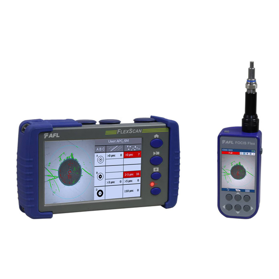
Page 48: Inspecting Fibers With Focis Series Inspection Probe And Flexscan
Inspecting Fibers with FOCIS Series Inspection Probe and FlexScan Optical connectors may be inspected using FOCIS Flex, FOCIS Duel, or FOCIS Lightning auto-focusing connector inspection probe with IEC pass/fail analysis . Captured fiber end- face images and pass/fail results are immediately displayed on the FOCIS probe display and on the paired FlexScan OTDR and may be saved in either FOCI or FlexScan . - Page 49 FOCIS Flex Inspection Probe Overview Display (2-inch Color LCD [320 x 240]) Screen title . Battery status icon . Image and information display area . F1 and F2 soft key labels area . Interfaces 10 Optical inspection port . 11 Adapter tip . 12 Dust cover .
-
Page 50: Pairing Flexscan With Focis Flex Inspection Probe
Pairing FlexScan with FOCIS Flex Inspection Probe To transfer fiber-end images from the FOCIS Flex inspection probe and display inspection results on FlexScan, you must Bluetooth pair your FOCIS Flex probe with FlexScan . Enable Bluetooth on FlexScan Home Screen General Settings Screen Bluetooth Screen From the Home screen, touch Settings... -
Page 51: Enable Bluetooth On Focis Flex
Enable Bluetooth on FOCIS Flex From FOCIS probe Main Menu, select Settings, then press Select . From the displayed Settings Menu, select Bluetooth, then press Select . Highlight Pair with New Device, then press Select . When a list of devices is displayed, navigate to and select Bluetooth ID of the FlexScan device, and then press Select to ‘Set as Default Device’... -
Page 52: Configuring Auto-Send
Configuring Auto-Send 1 . From the Main Menu, select Settings > Capture to display the Capture settings screen . 2 . Highlight and Select Auto-Send . 3 . Use Arrow Keys to enable Auto-Send on 1st Capture key or on 2nd Capture key . When Auto-Send is enabled, pressing Capture key from Live Image mode will initiate auto-focus (if enabled), capture image, analyze pass/fail (if enabled), then send image and pass/fail results to paired FlexScan OTDR . -
Page 53: Inspecting Optical Connectors
Inspecting Optical Connectors Once FlexScan is paired to FOCIS Flex with Bluetooth enabled on both units, perform the following steps . On FOCIS Flex: If testing an optical fiber connector, slide the ferrule of the optical fiber into the adapter tip installed on the FOCIS •... - Page 54 Inspecting Optical Connectors General Settings Screen On FlexScan: If the Received Image option is set to Popup Window • General Settings, inspection results received from FOCIS Flex will be immediately displayed on FlexScan screen . If the Received Image option is set to Show in Tray in General •...
-
Page 55: File Manager
File Manager Fiber test results may be stored in the FlexScan internal memory or external USB stick . Saved test results are organized into a Fiber Group sub-folder within a Project folder Results - Fibers Fiber Groups Projects The name of a saved result consists of several parameters, which are Save As Screen defined in the Save As screen S13 for 1310 nm... -
Page 56: Saving Results
Saving Results While in the Results view, touch Menu icon Touch ‘Save As’ . Edit [Project], [End1], [End2], [Cable] and [Fiber#] names used to identify saved results: touch any field to edit it . Touch Done when finished . Select if results are to be saved in SOR and/or PDF file format . Touch Results to view, navigate and select destination Project/ Fiber Group folder . -
Page 57: Saving To A Newly Created Folder
File Manager Saving to a Newly Created Folder While in the Results view, touch Menu From the displayed sub-screen, touch Save As to display the Results Manager screen . Define [Project], [End1], [End2], [Cable] and [Fiber#] fields used to name saved results . Touch Done when finished . -
Page 58: Viewing Saved Test Results
File Manager Viewing Saved Test Results To View Saved Test Results From the Home screen, touch ‘My Projects’ • Navigate through Project/Fiber Group/Fiber screens to locate the desired • test record, then touch it to display test results . – Touch up/down keys or swipe to scroll up/down through list of files . -
Page 59: File Manager
File Manager Deleting Projects/Jobs/Fibers From the Home screen, touch ‘My projects to display the Results Manager, which may be displayed as Projects screen, Jobs screen, or Fibers screen . Navigate through the Projects/Jobs/Fibers screen to locate the desired results . Touch Files icon control to enable ‘select’... -
Page 60: Transferring Results To A Pc Via Usb
Transferring Results to a PC via USB To transfer files from your FlexScan to a PC using a USB cable, perform Home Screen the following: Connect your FlexScan to a PC using the supplied micro-USB to USB • cable . Make sure the micro-plug is fully seated in your FlexScan . Touch the USB soft key on the FlexScan’s Home screen . -
Page 61: Back Up Saved Results To Usb Memory
Back Up Saved Results to USB Memory To back up internally stored results to USB memory stick: Plug external USB memory stick into FlexScan . From the Home screen, touch ‘My Projects’ . If Folder Up icon is shown, touch it to navigate up to Projects level until icon disappears Verify that Internal Memory is currently selected - memory... -
Page 62: Printing Results To Pdf
Printing Results to PDF Saved test results may be organized into reports and printed to PDF file format as needed . Navigate to the desired test results and touch Menu ( ) from the results display . Touch Print to PDF from the displayed menu . Select options to include cover page and configure content of printout . -
Page 63: How To View Device Information
How to View Device Information FlexScan software revision, serial number, and calibration date can be Home Screen viewed from the Device Information screen, which is accessed from the Home screen . From the Home screen, touch the Menu soft key . From the displayed sub-screen, touch Info . -
Page 64: General Information
. Any product that is found defective within the warranty period will, at the discretion of AFL, be repaired or replaced . Warranty will be voided if the product has been repaired or altered by other than an authorized AFL product repair facility, if the void sticker has been compromised, or which have been subject to misuse, negligence, or accident . - Page 65 Test & Inspection Thank you for choosing AFL Test & Inspection! www.AFLglobal.com or (800) 321-5298, (603) 528-7780...
Need help?
Do you have a question about the FlexScan FS300 and is the answer not in the manual?
Questions and answers
if there is a break in the fiber will it show up red on the link map
Yes, a break in the fiber will show up red on the LinkMap for the AFL FlexScan FS300 if it causes one or more events to fail, as red indicates failed events based on loss or reflectance thresholds.
This answer is automatically generated