Table of Contents
Advertisement
TECHNICAL MANUAL
Of
Intel Bay Trail Series CPU
Based Mini-ITX M/B
NO. G03-NLBT-F
Revision: 2.0
Release date: June 16, 2015
Trademark:
* Specifications and Information contained in this documentation are furnished for information use only, and are
subject to change at any time without notice, and should not be construed as a commitment by manufacturer.
Advertisement
Table of Contents

Subscribe to Our Youtube Channel
Related Manuals for JETWAY NLBT-I1900 Series


Summary of Contents for JETWAY NLBT-I1900 Series
- Page 1 TECHNICAL MANUAL Intel Bay Trail Series CPU Based Mini-ITX M/B NO. G03-NLBT-F Revision: 2.0 Release date: June 16, 2015 Trademark: * Specifications and Information contained in this documentation are furnished for information use only, and are subject to change at any time without notice, and should not be construed as a commitment by manufacturer.
- Page 2 Environmental Protection Announcement Do not dispose this electronic device into the trash while discarding. To minimize pollution and ensure environment protection of mother earth, please recycle.
-
Page 3: Table Of Contents
TABLE OF CONTENT ENVIRONMENTAL SAFETY INSTRUCTION ................iii USER’S NOTICE ........................iv MANUAL REVISION INFORMATION ..................iv ITEM CHECKLIST ........................iv CHAPTER 1 INTRODUCTION OF THE MOTHERBOARD FEATURE OF MOTHERBOARD ................1 SPECIFICATION ......................2 LAYOUT DIAGRAM ....................CHAPTER 2 HARDWARE INSTALLATION JUMPER SETTING ..................... -
Page 4: Environmental Safety Instruction
Environmental Safety Instruction Avoid the dusty, humidity and temperature extremes. Do not place the product in any area where it may become wet. 0 to 60 centigrade is the suitable temperature. (The figure comes from the request of the main chipset) ... -
Page 5: User's Notice
USER’S NOTICE COPYRIGHT OF THIS MANUAL BELONGS TO THE MANUFACTURER. NO PART OF THIS MANUAL, INCLUDING THE PRODUCTS AND SOFTWARE DESCRIBED IN IT MAY BE REPRODUCED, TRANSMITTED OR TRANSLATED INTO ANY LANGUAGE IN ANY FORM OR BY ANY MEANS WITHOUT WRITTEN PERMISSION OF THE MANUFACTURER. -
Page 6: Chapter 1 Introduction Of The Motherboard Feature Of Motherboard
Chapter 1 Introduction of the Motherboard Feature of Motherboard ® Onboard Intel Bay Trail Series Processor, with low power consumption never denies high performance Support DDR3L SO-DIMM 1066/1333 MHz up to 8GB Support 1 * SATAII (3Gb/s) Device ... -
Page 7: Specification
1-2 Specification Spec Description Mini-ITX form factor ; Design PCB size: 17.0 x 17.0 cm ® Intel Bay Trail-D/M/I series CPU Embedded CPU 1* DDR3L SO-DIMM slot Support DDR3L 800/1066/1333 MHz SDRAM, expandable to Memory Slot ... - Page 8 1*SPEAK_CON1 header 1*SPEAK_CON2 header 1* SPDIF Out header 5 * COM header (COM2 with support for RS422/RS485 function) 1* TX_RXCOM2 header 1 * Front panel header 1 *GPIO header 1* 9-pin USB 2.0 header for 2* USB 2.0 ports ...
-
Page 9: Layout Diagram
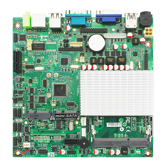
1-3 Layout Diagram Rear IO Diagram For NLBT-I1900/NLBT-I2930/ NLBT-I1800 Series: USB 2.0 Port RJ-45 LAN Port COM1 Port VGA Port DC12V Line-OUT Power-in Connector USB 3.0 Port USB 2.0 Ports For NLBT-I1900-2L Series: RJ-45 LAN Ports Parallel Port USB 2.0 Port DC12V Line-OUT Power-in... - Page 10 Motherboard Internal Diagram-1 For NLBT-I1900/NLBT-I2930/ NLBT-I1800 Series: ATX12V Power Connector HDMI Port Header DC12V Power-in Connector Intel CPU USB 2.0 Port Over USB 3.0 Port DDR3L SODIMM Slot VGA Port Header VGA Port PS2 KB/MS Header Parallel Port Header SATA Hard Disk Power-Out Connector CPUFAN1 Header COM1 Port...
- Page 11 Motherboard Internal Diagram-2 For NLBT-I1900-2L Series: ATX12V Power Connector HDMI Port Header DC12V Power-in Connector Intel CPU USB 2.0 Port Over USB 3.0 Port DDR3L VGA Port Header SODIMM Slot PS2 KB/MS Header Parallel Port over VGA Port & COM1 Port SATA Hard Disk Power-Out Connector CPUFAN1 Header...
- Page 12 Internal Diagram-Back Side: *SIM Card Slot -Optional *SIM card slot is available to specific models. Please refer to the product you purchase for actual specification.
- Page 13 Motherboard Jumper Position JBAT JCOMP1 ME_RTC COPEN1 JCOMP2 *JCOM2...
- Page 14 Jumper Jumper Name Description JBAT CMOS RAM Clear Function Setting 2-pin Block ME_RTC Clear ME RTC Function Setting 2-pin Block COPEN1 Case Open Message Display Function 2-pin Block INVERTER VCC 3.3V/5V/12V Select 4-pin Block LVDS VCC 3.3V/5V/12V Select 4-pin Block JCOMP1 COM1 Header Pin9 Function Select 6-Pin Block...
- Page 15 Headers Header Name Description FP_AUDIO1 Front Panel Audio Header 9-pin Block SPEAK_CON1 Left Speaker Header 2-pin Block SPEAK_CON2 Right Speaker Header 2-pin Block SPDIF Header 2-pin Block HDMI_SPDIF COM2/3/4/5/6 Header X 5 9-pin Block Serial Port TX-RXCOM2 RS422/RS485 Header 4-pin Block JW_FP Front Panel Header(PWR LED/ HD 9-pin Block...
-
Page 16: Hardware Installation
Chapter 2 Hardware Installation 2-1 Jumper Setting JBAT (2-pin): Clear CMOS Setting JBAT 1-2 Open: Normal; 1-2 Closed:Clear CMOS CMOS Clear Setting ME_RTC (2-pin): Clear ME_RTC Function Setting ME_RTC 1-2 Open: Normal; 1-2 Closed: Clear ME_RTC. - Page 17 COPEN1 (2-pin): Case Open Message Display Function Select COPEN1 Pin 1-2 Closed: When Case open function pin short to GND, the Case open function was detected. When Used, needs to enter BIOS and enable ‘Case Open Detect’ function. In this case if your case is removed, next time when you restart your computer, a message will be displayed on screen to inform you of this.
- Page 18 JP4 (4-pin): LVDS VCC 3.3V/5V/12V Select JP4→LVDS VCC 2-4 Closed: 3-4 Closed: 4-6 Closed: VCC=3.3V; VCC= 5V; VCC= 12V. JCOMP1 (6-pin): COM1 Port Pin9 Function Select JCOMP1→COM1 1-2 Closed: RS232; 3-4 Closed : +12V; 5-6 Closed : +5V.
- Page 19 JCOMP2 (6-pin): COM2 Header Pin9 Function Select JCOMP2→COM2 1-2 Closed: RS232; 5-6 Closed : +5V 3-4 Closed : +12V JCOM2 (6-pin): COM2 Header RS232/RS485/RS422 Function Select → JCOM2 COM2 5-6 Closed : RS422. 1-2 Closed: RS232; 3-4 Closed : RS485;...
-
Page 20: Connectors And Headers
Connectors and Headers 2-2-1 Connectors (1) Rear I/O Panel Icon Name Function For user to connect compatible power DC-in 12V Power adapter to provide power supply for the Connector system. To connect USB keyboard, mouse or other USB 2.0 Port devices compatible with USB specification. - Page 21 (2) COM1 (9-pin block): Serial Port Connector Pin No. Definition Pin 1 RING/5V/12V (JCOMP1) (3) DC12V1 (4-pin block): DC12V Power Connector Pin1 Pin2 Pin3 Pin4 Pin No. Definition +12V DC_IN +12V DC_IN...
- Page 22 (4) ATX12V (4-pin block): ATX12V Type Power Connector Pin1 Pin No. Definition +12V +12V (5) SATA1 (7-pin block)::SATAII Port connector This connector is a high-speed SATAII port that supports 3 GB/s transfer rate. Pin No. Defnition...
-
Page 23: Headers
(6) SATAPW(4-pin): SATA Hard Disk Power-out Connector Pin 1 2-2-2 Headers (1) FP_AUDIO1 (9-pin): Line-Out, MIC-In Header This header connects to Front Panel Line-out, MIC-In connector with cable. Pin 1... - Page 24 (2) SPEAK_CON1 (2-pin)/ SPEAK_CON 2 (2-pin): Speaker Headers Pin1 Pin1 SPEAK_CON1 Header SPEAK_CON2 Header (3) SPDIF (2-pin): HDMI_SPDIF Out Header Pin1...
- Page 25 (4) COM2/3/4/5/6 (9-Pin): Serial Port Headers Pin1 (5) TX-RXCOM2 (4-Pin): RS422/485 Header Pin 1 *Notice: User needs to go to BIOS to set ‘Transmission Mode Select’ as [RS422/RS485] for COM2 as well (refer to Page 34).
- Page 26 (6) JW-FP (9-pin): Front Panel Header RSTSW PWRBTN PWRLED- HDDLED- HDDLED+ PWRLED+ Pin 1 (7) GPIO (10-pin): GPIO Header GPIO_37 GPIO_36 GPIO_34 GPIO_35 GPIO_32 GPIO_33 GPIO_31 GPIO_30 Pin 1...
- Page 27 (8) F_USB1 (9-pin): USB 2.0 Port Header +DATA +DATA -DATA -DATA Pin 1 (9) PS2KBMS (6-pin): PS/2 Keyboard & Mouse Header Pin1...
- Page 28 (10) LPT1 (25-pin): Parallel Port Header Pin 14 Pin 1 Pin NO. Pin Definition Pin NO. Pin Definition STB- AFD- Pin 1 Pin 14 PRD0 ERR- Pin 2 Pin 15 PRD1 INIT- Pin 3 Pin 16 PRD2 SLIN- Pin 4 Pin 17 PRD3 Pin 5...
- Page 29 (11) HDMI (20-pin): HDMI Header Pin 1 Pin 2 Pin NO. Pin Definition Pin NO. Pin Definition HDMI_TXP2 Pin 1 Pin 2 HDMI_TXP1 HDMI_TXN2 Pin 3 Pin 4 Pin 5 HDMI_TXN1 Pin 6 HDMI_TXP0 Pin 7 Pin 8 Pin 9 HDMI_TXCP Pin 10 HDMI_TXN0...
- Page 30 (12) CPUFAN1 (4-pin)/SYSFAN1 (3-pin): FAN Headers Pin1 CPUFAN1 SYSFAN1 Pin1 +12V Fan Power Fan Speed (13) VGA1 (12-pin): VGA Header Pin No. Definition VCC5(Reserved) VGA_VSYNC VGA_HSYNC GND_RED RED_VGA GND_GRN GRN_VGA Pin 1 GND_BLUE BLUE_VGA DDC_DATA DDC_CLK...
- Page 31 (14) JP2 (2-pin): LVDS Panel Brightness Adjustment Header Pin1 (15) INVERTER (6-Pin): LVDS1 Inverter Header Pin No. Definition BKLT_PWR1 BKLT_PWR2 BKLT_EN Pin 1 BKLT_PWM GND1 GND2...
- Page 32 (16) LVDS (30-Pin): 24-bit dual channel LVDS Header Pin 2 Pin 1 Pin NO. Pin Define Pin NO. Pin Define Pin 1 LVDS_VCC Pin 2 LVDS_VCC Pin 3 LVDS_VCC Pin 4 Pin 5 Pin 6 Pin 7 LVDSA_DATAN0 Pin 8 LVDSA_DATAP0 Pin 9 LVDSA_DATAN1...
-
Page 33: Chapter 3 Introducing Bios
Chapter 3 Introducing BIOS Notice! The BIOS options in this manual are for reference only. Different configurations may lead to difference in BIOS screen and BIOS screens in manuals are usually the first BIOS version when the board is released and may be different from your purchased motherboard. -
Page 34: Bios Menu Screen
BIOS Menu Screen The following diagram show a general BIOS menu screen: Menu Bar General Help Items Current Setting Value Menu Items Function Keys BIOS Menu Screen Function Keys In the above BIOS Setup main menu of, you can see several options. We will explain these options step by step in the following pages of this chapter, but let us first see a short description of the function keys you may use here: ... -
Page 35: Getting Help
Press <Enter> to select. Press <+>/<–> keys when you want to modify the BIOS parameters for the active option. [F1]: General help. [F2]: Previous value. [F3]: Optimized defaults. [F4]: Save & Reset. Press <Esc> to quit the BIOS Setup. Getting Help Main Menu The on-line description of the highlighted setup function is displayed at the top right... -
Page 36: Main Menu
Main Menu Main menu screen includes some basic system information. Highlight the item and then use the <+> or <-> and numerical keyboard keys to select the value you want in each item. System Date Set the date. Please use [Tab] to switch between date elements. System Time Set the time. -
Page 37: Advanced Menu
3-7 Advanced Menu OS Selection The optional settings: [Windows 8.X]; [Android]; [Windows 7]. * Note: User need to go to this item to select the OS mode before installing corresponding OS driver, otherwise problems will occur when installing the driver. ... - Page 38 ACPI Sleep State Use this item to select the highest ACPI sleep state the system will enter when the suspend button is pressed. The optional settings are: [Suspend Disabled]; [S3 (Suspend to RAM)]. EUP Function The optional settings: [Disabled]; [Enabled]. This item should be set as [Disabled] if you wish to have all active wake-up functions.
- Page 39 Configuration/Serial Port 5 Configuration / Serial Port 6 Configuration Press [Enter] to make settings for the following items: Serial Port Configuration Serial Port Use this item to enable or disable serial port (COM). Change Settings Use this item to select an optimal setting for super IO device. ...
- Page 40 User can set a value in the range of [4] to [255]. WatchDog Timer Unit The optional settings are: [Sec.]; [Min.]. Case Open Detect Use this item to detect case has already open or not, show message in POST. The optional settings: [Disabled]; [Enabled]. ...
- Page 41 The optional settings: [Disabled]; [Enabled]. Hardware Prefetcher The optional settings are: [Disabled]; [Enabled]. Use this item to turn on/off the Mid Level Cache (L2) streamer prefetcher. Adjacent Cache Line Prefetch The optional settings are: [Disabled]; [Enabled]. Use this item to turn on/off prefetching of adjacent cache lines. Intel Virtualization Technology The optional settings: [Enabled];...
- Page 42 EIST The optional settings: [Enabled]; [Disabled]. Use this item to enable or disable Intel SpeedStep. CPU C Status Report The optional settings: [Disabled]; [Enabled]. Use this item to enable or disable CPU C status report to OS. *When set as [Enabled], the following sub-items shall appear: Max CPU C-state This option controls Max C state that the processor will support.
- Page 43 This item is for BIOS reaction on INT19 trapping by Option ROM. The optional settings are: [Immediate]; [Postponed]. [Immediate]: To execute the trap right away; [Postponed]: To execute the trap during legacy boot. Option ROM execution order Storage This item controls the execution of UEFI and Legacy Storage OpROM. The optional settings are: [Do not launch];...
-
Page 44: Chipset Menu
USB Mass Storage Driver Support The optional settings are: [Disabled]; [Enabled]. 3-8 Chipset Menu North Bridge Press [Enter] to view current using memory information and make settings for the following sub-items: IGD Turbo Enable The optional settings are: [Enabled]; [Disabled]. DVMT Pre-Allocated Use this item to select DVMT 5.0 pre-allocated (fixed) graphics memory size used by the internal graphics device. - Page 45 DVMT Total Gfx Mem Use this item to select DVMT 5.0 total graphics memory size used by the internal graphics device. The optional settings are: [128M]; [256M]; [MAX]. Spread Spectrum Clock The optional settings are: [Enabled]; [Disabled]. RC6(Render Standby) Use this item to enable or disable render standby support. Primary IGFX Boot Display Use this item to select the video device which will be activated during POST.
- Page 46 XHCI Mode The system will show whether current XHCI support is enabled or disabled. USB 2.0 (EHCI) Support The system will show whether current USB 2.0 (EHCI) support is enabled or disabled. Audio Controller Use this item to control the detection of the Azalia HD Audio device. The optional settings are: [Disabled];...
-
Page 47: Security Menu
3-9 Security Menu Security menu allow users to change administrator password and user password settings. -
Page 48: Boot Menu
3-10 Boot Menu Boot Configuration Setup Prompt Timeout Use this item to set number of seconds to wait for setup activation key. Bootup Numlock State Use this item to select keyboard numlock state. The optional settings are: [On]; [Off]. Fast Boot The optional settings are: [Enabled];... - Page 49 will not be shown during POST. EFI driver will still be installed with EFI OS. USB Support The optional settings are: [Disabled]; [Full Initial]; [Partial Initial]. [Disabled]: All USB devices will NOT be available until after OS boot; [Partial Initial]: USB mass storage and specific USB port/device will NOT be available before OS boot;...
-
Page 50: Save & Exit Menu
3-11 Save & Exit Menu Save Changes and Reset This item allows user to reset the system after saving the changes. Discard Changes and Reset This item allows user to reset the system without saving any changes. Save Options Save Changes This item allows user to save changes done so far to any of the setup options. - Page 51 Use this item to save the changes done so far as user defaults. Restore User Defaults Use this item to restore defaults to all the setup options. Boot Oerride UEFI: Built-in EFI Shell Press this item and a dialogue box shall appear to ask if user wish to save configuration and reset.
Need help?
Do you have a question about the NLBT-I1900 Series and is the answer not in the manual?
Questions and answers