
Related Manuals for Uplink 4550-CB


Summary of Contents for Uplink 4550-CB
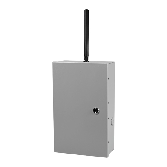
- Page 1 ® 4550-CB 4G CELLULAR ALARM COMMUNICATOR WIRELESS COMMERCIAL SECURITY APPLICATIONS PRIMARY OR BACKUP COMMUNICATIONS INSTALLATION & USER’S GUIDE PRODUCT ID # 202132UP455012...
- Page 2 4550-CB 4550-CB © 2013 Uplink Security LLC. All rights reserved. Uplink is a trademark of Uplink Security LLC. No part of this publication may be reproduced or used in any form without permission in writing from Uplink. This includes electronic or mechanical means, such as photocopying, recording, or information storage and retrieval systems.
-
Page 3: Table Of Contents
B. DIP Switch Settings ..............15 C. LEDs .....................16-18 D. Locating and Installing the 4550-CB ..........19-22 E. Connecting the 4550-CB to the Alarm Panel & Telephone Jack ..23-25 F. Activating the 4550-CB Unit ............26-27 G. Programming and Central Station Reporting .......28-30 H. -
Page 4: Introduction
® 4550-CB INTRODUCTION Uplink’s MODEL 4550-CB GSM Alarm Communicator is a UL Listed alarm and critical event communicator designed to interface with most manufacturers’ alarm panels that incorporate a digital telephone dialer. The 4550-CB features a “dialer capture” interface to the alarm panel. If the alarm panel’s TELCO connection is compromised, or if no TELCO connection is present, the 4550-CB will “intercept”... -
Page 5: Key Features
Network as the communications path for sending event information. C. Panel to 4550-CB Cable Supervision. Monitors continuity of the cable connecting the panel’s telephone dialer to the 4550-CB. This feature is activated through the web site www.uplink.com or by calling Uplink Customer Service at 1-888-9-UPLINK (1-888-987-5465). - Page 6 • No Central Station Acknowledgement • AC Loss • Low or Missing Battery • Telco Line Loss • Panel/MODEL 4550-CB Cable Supervision Trouble • Activation of Input(s) • Enclosure Tamper • Unit Disabled by Dealer Command • Watchdog Circuit Activation •...
-
Page 7: Key Features
Received Signal Strength reading e. programming inputs and other internally generated events L. UL Listed. The Model 4550-CB unit is UL Listed and conforms to ANSI/UL Standards 365 and 1610 for Police Station Connected and Central Station Monitored commercial burglar alarm systems as well as UL 1635 Digital Alarm Communicator System Units. -
Page 8: Warranty Information And Liability Waiver
12-month warranty period, Uplink will, at its sole option and at no charge, repair or replace it or arrange for its repair or replacement. Uplink’s agreement to repair (using new or... -
Page 9: Limitations Of Liability
The warranty set forth furthermore does not cover Uplink Devices that (a) have been improperly installed, operated, or serviced; (b) have been tampered with; or (c) have been subjected to environmental extremes. - Page 10 AND LIABILITY WAIVER (cont.) MORE RELATED OR UNRELATED CLAIMS EXCEED AN AMOUNT EQUAL TO THE AGGREGATE AMOUNT PAID BY THE CLAIMANT FOR UPLINK SERVICE DURING THE 12 MONTH PERIOD PRECEDING THE DATE OF THE EARLIEST EVENT GIVING RISE TO THE SUBJECT CLAIM(S).
-
Page 11: Fcc And Industry Canada Regulatory Compliance
4G CELLULAR ALARM COMMUNICATOR FCC & INDUSTRY CANADA REGULATORY COMPLIANCE Part 15 This device complies with Part 15 of the FCC Rules. Operation is subject to the following two conditions: (1) this device may not cause harmful interference, and (2) this device must accept any interference received, including interference that may cause undesired operation. -
Page 12: Part 68
This equipment complies with Part 68 of the FCC rules and the requirements adopted by the ACTA. On the side of the cover of the 4550-CB is a label that contains the product identifier, US: 3F0MO00BANYNETFDM. If requested, this number must be provided to the telephone company. -
Page 13: Fcc And Industry Canada Regulatory Compliance
The 4550-CB is not designed to be repaired in the field by an Installer. Repairs to this unit should only be undertaken by qualified Uplink Security personnel. -
Page 14: Fcc Rf Exposure Information
® 4550-CB FCC RF EXPOSURE INFORMATION In August 1996 the Federal Communications Commission (FCC) of the United States with its action in Report and Order FCC 96-326 adopted an updated safety standard for human exposure to radio frequency electromagnetic energy emitted by FCC regulated transmitters. -
Page 15: Technical Support
Technical support requires the caller to provide: • Login name • Password • Serial number of the 4550-CB UPLINK Technical Support 3330 Cumberland Blvd. SE Suite 700 Atlanta, GA 30339 1-888-9-Uplink (1-888-987-5465) Fax: 770-693-3501 For Customer Support, call 888-987-5465, or visit www.uplink.com... -
Page 16: Installation
Proximity to a Plug for the AC transformer. c. Proximity to the alarm panel and where to route the 4550-CB unit’s relay outputs that connect to the alarm panel unit’s inputs, and vice versa. (These wires will need to be in conduit for a UL certificated installation. -
Page 17: Leds
S1 restored to its OFF position. All website configurations will be erased by using S1. C. LEDs Normal Mode: Upon initial power up, the 5 LEDs on the 4550-CB will begin to function as follows: LED STATUS MEANING... - Page 18 ® 4550-CB INSTALLATION (cont.) LED STATUS MEANING Telco LED (#2) Phone line is not monitored GREEN Phone line is OK (Telco primary mode), Panel or Extension is on-hook Flashing Panel or Extension Line is off-hook Phone line Trouble Condition Trouble LED (#3)
- Page 19 4G CELLULAR ALARM COMMUNICATOR INSTALLATION (cont.) RSSI Mode: When the 4550-CB is placed in Received Signal Strength Indicator (RSSI) Mode by turning Dipswitch S4 to ON, the five LEDs indicate the following signal strength information: RECEIVED SIGNAL APPEARANCE OF LEDs (#1 thru #5) STRENGTH ≥...
-
Page 20: Locating And Installing The 4550-Cb
Note: For a UL Certificated Installation, additional installation requirements and tested configurations are located in the UL compliance section. The Model 4550-CB unit comes in a metal enclosure. The installer needs to supply the unit’s 16.5 VAC – 45VA transformer (Recommended Transformers: Elk TRG1640, MG Electronics Model MGT1640 or equivalent) and a 12VDC, 5 AH backup battery (Recommended Battery: Powersonic PS-1250F1 or equivalent). - Page 21 Note: All Circuits are power-limited, except for battery connections. A ¼ inch To Alarm Panel spacing is required between power- limited circuits and non-power limited circuits for UL compliant installations FIGURE 1: 4550-CB PC BOARD DETAILS (INSTALLATION continued next page)
- Page 22 4550-CB INSTALLATION (cont.) Position the bottom of the 4550-CB enclosure where it will be installed. Use four (4) #6 screws and mount the unit using the four holes in the enclosure’s back. The 4550-CB unit’s dimensions are shown in Figure 2.
- Page 23 JP13. 10. Before connecting the alarm panel and the 4550-CB, first: a. Return Dipswitch #4 (S4) to the OFF position. b. Disconnect the AC transformer from its power outlet.
-
Page 24: Connecting The 4550-Cb To The Alarm Panel & Telephone Jack
INSTALLATION (cont.) E. Connecting The 4550-CB to the Alarm Panel and Telephone Jack IMPORTANT: Make all of the connections to the 4550-CB in the powered down state. Once all of the connections have been established, turn power on. 1. First, remove AC and battery power from the 4550-CB, then proceed as follows: 2. - Page 25 Energized closed (N.O.) Failure to receive ACK from Central Station Energized open (N.C.) Total failure of Model 4550-CB See Figure 3 as an example of how to connect the 4550-CB to the alarm panel and the telephone line. (INSTALLATION continued next page)
- Page 26 Blue Wire (#7) Switch Note: To supervise the Telco cable connection to the Model 4550-CB unit, short wires #2 and #7 together. FIGURE 3: EXAMPLE CONNECTIONS BETWEEN THE 4550-CF AND THE ALARM PANEL. REFER TO UL COMPLIANCE SECTION FOR SPECIFIC UL WIRING REQUIREMENTS AND INSTALLATION NOTES.
-
Page 27: Activating The 4550-Cb Unit
A confirmation box will appear saying “Congratulations, your new Uplink Account was successfully created!” Press OK. f. Select the UPLINK DEALERS new/existing dealer button at the top of the page. Enter the newly created Login Name and Password to sign into the website. - Page 28 Activation is complete once a successful test message is displayed. Existing Dealer 4550-CB Activation: For dealers/customers who already have an account with Uplink, go to the Uplink web site (www.uplink.com). a. Enter the Login Name and Password. Wait about 20 seconds for the next web page to completely install.
-
Page 29: Programming And Central Station Reporting
The following parameters can be configured from the Dealer Web Site; 1. Dialer Intercept Mode Status (Default=Intercept determined by Line Monitor). The 4550-CB normally uses its built-in Telephone Line Monitoring circuit to determine whether the unit should intercept the alarm panel’s digital dialer or leave it connected to the premises telephone line. - Page 30 6. Definition of Output Relay (Default = #1 Loss of Cellular Service, #2 Central Station ACK Failure, #3 Total Unit Failure) There are 11 Trouble states that can be declared by the 4550-CB. Each of these states can be programmed from the Dealer Web Site to activate one of the three Output Relays.
-
Page 31: Default Event/Email Messages
ALARM COMMUNICATOR INSTALLATION (cont.) 7. Send Trouble Condition to Central Station Any or all of the Trouble Conditions detectable by the 4550-CB can be programmed to report that condition (and its Restoral) to the monitoring Central Station. See APPENDIX A for a list of Contact ID, SIA, Modem IIe/IIIa/IIIa and DMP format event codes generated by the 4550-CF that can be sent to the central station receiver. -
Page 32: Completing The Installation And Testing
Reconnect the Telco Line. d. If using one or both of the inputs on the 4550-CB, check to ensure both are properly activated and reporting to the central station. e. If using one or more of the Output Relays on the 4550-CB, then go back to the Dealer Web Site and use the Switch Output Relay command to test each relay. -
Page 33: Ul Compliance Section Part 1 - Installation Requirements
Commercial Burglary (UL 1610 - Category AMCX, UL 365 – Category APAW) 1. For a UL Certificated Installation, the 4550-CB must be connected to a Listed panel, sch as a DSC PC1616 panel and a Listed DACR, such as the DSC, Model SG-System III and configured to communicate via Contact ID protocol. - Page 34 UL COMPLIANCE SECTION – INSTALLATION REQUIREMENTS (cont.) 5. The Model 4550-CB unit must be located within the same room as the alarm panel and a maximum of 20 feet of the alarm panel. The 4550-CB must be installed at the protected premises.
- Page 35 13. The two (2) tamper switches provided with the Model 4550-CB must be installed and connected to a 24 hour alarm input on either the Model 4550-CB unit or the alarm panel. The lock and key provided with the unit must also be installed and used.
- Page 36 16. The S3 switch must be returned to the OFF position for normal operation and for a proper UL installation. 17. The wire connecting the 4550-CB to the POTS line shall be a minimum of 26 AWG and must use a minimum 300V insulation jacket.
- Page 37 1/4” inch away from all power-limited wiring. 27. The 4550-CB has two EOLR supervised inputs that report to the central station when activated. These inputs are disabled in the default state and must be enabled via the Dealer Web Site.
-
Page 38: Specifications
® 4550-CB SPECIFICATIONS Panel to 4550-CB Interface Line Voltage 48 VDC On-Hook Dial tone 350 + 440 Hz +/- 0.2% Distortion All tones less than 2.0% DTMF twist accuracy +/- 1 dB Panel tones +/- 0.2% Receive level minimum - 45 dBm... - Page 39 4G CELLULAR ALARM COMMUNICATOR SPECIFICATIONS Power (cont.) Maximum Battery charging current 700 mA for 5.0aH battery Maximum full charge DC voltage 13.6V +/- 0.2V Maximum Ripple 20mV Radio Frequencies 850/1900 MHz Avg. Current 290 mA Peak Current DC Voltage 3.3- 4.2 V D.C. Sensitivity -109 dB (typical) Environmental...
-
Page 40: Dmp Event Codes
APPENDIX A: CONTACT ID, SIA, MODEM IIe/IIIa/IIIa DMP EVENT CODES Following is a list of event codes that can be sent to the central station receiver for events generated by the 4550-CB unit EVENT DESCRIPTION CONTACT ID SIA DC-03 MODEM lle/... - Page 41 4G CELLULAR ALARM COMMUNICATOR APPENDIX A: CONTACT ID, SIA, MODEM IIe/IIIa/IIIa DMP EVENT CODES (cont.) EVENT DESCRIPTION CONTACT ID SIA DC-03 MODEM lle/ DMP EVENT EVENT CODE EVENT CODE llla/lllla CODE Low Battery Restoral R302 Zs...001 Low Temperature E159 Za...A1 Low Temperature R159 Zr...A1...
- Page 42 ® 4550-CB APPENDIX A: CONTACT ID, SIA, MODEM IIe/IIIa/IIIa DMP EVENT CODES (cont.) EVENT DESCRIPTION CONTACT ID SIA DC-03 MODEM lle/ DMP EVENT EVENT CODE EVENT CODE llla/lllla CODE Test E602 Zs...007 Trouble (generic) E300 Zt...BL Trouble Restoral R300 Zr...BL...
-
Page 43: Appendix B: 4550-Cb Default Event Codes
APPENDIX B: MODEL 4550-CB DEFAULT EVENT CODES The 4550-CB can be set to send both the Alarm/Trouble condition and the Restoral condition for all of the events listed below. Reporting individual events can be controlled from the Dealer Web Site. - Page 44 ® 4550-CB APPENDIX B: MODEL 4550-CB DEFAULT EVENT CODES (cont.) EVENT DESCRIPTION CONTACT SIA DC-03 MODEM ZONE NO. ID EVENT EVENT lle/llla/llla REPORTED CODE CODE Watchdog Circuit Trouble E616 Watchdog Circuit Restoral R616 Input 1 Alarm E140 Input 1 Normal...
- Page 45 4G CELLULAR ALARM COMMUNICATOR UPLINK 4G CELLULAR ALARM COMMUNICATOR INSTALLATION, OPERATION AND PROGRAMMING GUIDE © 2013 Uplink Security LLC. All rights reserved. Uplink is a trademark of Uplink Security LLC. GUIDE 00-25580-876 (REV. A) ® 3330 CUMBERLAND BLVD, SUITE 700, ATLANTA, GA 30339 888-987-5465 (888-9-UPLINK) WWW.UPLINK.COM...
-
Page 46: Product Information
® FOR SALES & PRODUCT INFORMATION Uplink 3330 Cumberland Blvd Suite 700 Atlanta, GA 30339 1-(888) 9-UPLINK sales@uplink.com www.uplink.com FOR TECHNICAL SUPPORT Please visit our website at www.uplink.com.
Need help?
Do you have a question about the 4550-CB and is the answer not in the manual?
Questions and answers