
Related Manuals for Uplink 2550


Summary of Contents for Uplink 2550
- Page 1 To download a copy of this manual go to “Quick Links” at www.numerexsolutions.com. 2550 PLINK ODEL GSM A LARM OMMUNICATOR ID # 19-25133-841 RODUCT NSTALLATION PERATIONS AND ROGRAMMING UIDE...
-
Page 2: Table Of Contents
2. Key Features..............4 A. Full Event Reporting ..........4 B. Telephone Line Supervision ........4 C. Panel to MODEL 2550 Cable Supervision ....4 D. Zone Inputs .............. 4 E. Three Relay Outputs ..........4 F. Power Source Monitoring (AC & Low Battery Reporting) .............. - Page 3 B. Household Burglary (UL 1023 - Category NBSX, and evaluated to UL 1635 - Category AMCX) .... 22 9. Specifications ..............23 Appendix A: Contact ID and SIA Event Codes ....25 Appendix B: Model 2550 Default Event Codes ....26...
-
Page 4: Introduction
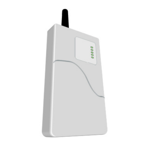
Uplink’s MODEL 2550 GSM Alarm Communicator is a UL Listed alarm communicator designed to interface with most manufacturer’s alarm panels that incorporate a digital telephone dialer. A key feature of the 2550 is a “dialer capture” interface to the alarm panel. If the alarm panel’s TELCO connection is compromised, or if no TELCO connection is present, the 2550 will “intercept ”... -
Page 5: Power Source Monitoring
. Ships with an active SIM card, with easy activations available via the Web at www.numerexsolutions.com or by calling Uplink Customer Service at 1-888-9-UPLINK (1-888-987-5465). Requires the central station receiver phone number and/or its IP address and Port number. K. Web-based Services . Available at www.numerexsolutions.com... -
Page 6: Warranty Information And Liability Waiver
These terms and conditions are a legal contact between you and the Company and supplement (but do not supersede) the terms and conditions of any master agreement between you and Uplink Security, Inc. (the “Company”) governing your purchase of the Product from the Company. By using, marketing, or selling the Product, you agreement to these terms and conditions. -
Page 7: Indemnification
INDEMNIFICATION You agree to defend, hold harmless, and indemnify the Company and its affiliates and their respective officers, directors, employees, and agents from and against any and all damages, liability, costs, and expenses (including, without limitation, reasonable attorneys’ fees) arising out of or relating to (a) any claim for breach of this Agreement by you;... -
Page 8: Part 68
Part 68 This equipment complies with Part 68 of the FCC rules and the requirements adopted by the ACTA. On the side of the cover of the 2550 is a label that contains the product identifier, US: 3F0MO00BANYNETFDM. If requested, this number must be provided to the telephone company. -
Page 9: Fcc Rf Exposure Information
The 2550 is not designed to be repaired in the field by an Installer. Repairs to this unit should only be undertaken by qualified Uplink Security personnel. -
Page 10: Technical Support
Plug in the AC transformer. c. Proximity to the alarm panel and where to route the 2550 unit’s relay outputs that connect to the alarm panel unit’s inputs, and vice versa. (These wires will need to be in conduit for a UL certificated installation. -
Page 11: Leds
This switch must be returned to the OFF position for normal operation, and for a proper UL installation. C. LEDs Normal Mode: Upon initial power up, the 5 LEDs on The 2550 will begin to function as follows: LED S... - Page 12 Unit is functioning normally Flashing S1 is ON after reset RSSI Mode: When the 2550 is placed in Received Signal Strength Indicator (RSSI) Mode by turning Dipswitch S4 to ON, the five LEDs indicate the follow signal strength information: Received Signal Strength Appearance of LEDs (#1 thru #5) ≥...
-
Page 13: Locating And Installing The 2550 Unit
D. Locating and Installing the 2550 The 2550 is housed in a plastic enclosure and requires an additional 16.5 VAC – 40VA transformer (Recommended Transformers: Ademco 1361, MG Electronics Model MGT1640 or equivalent) and backup 1.4 AH battery (Recommended Battery: Powersonic PS-1212 or equivalent). The recommended battery measures 3.8 inches long by 2.3 inches high by 1.7 inches wide. - Page 14 Figure 1: Parts on the 2550 PC Board...
- Page 15 Position the bottom of the 2550 enclosure where it will be installed. Use four (4) #6 screws and mount the unit using the four holes in the enclosure’s plastic bottom. The 2550 unit’s dimensions are shown in Figure 2. Figure 2: Inside & Outside Mounting Dimensions for the 2550 5.
-
Page 16: Connecting The 2550 To The Alarm Panel And Telephone Jack
4. Outputs The 2550 has three relay outputs that can be used to activate inputs on the alarm panel or for other local purposes. Decide on how to use these outputs, then wire them to terminal strip JP10 as follows:... -
Page 17: Activating The 2550 Unit
Failure to receive ACK from Central Station Energized open (N.C.) Total failure of Model 2550 See Figure 3 as an example of how to connect the 2550 to the alarm panel and the telephone line. Figure 3: Connections Between the 2550 and the Alarm Panel F. -
Page 18: Programming And Central Station Reporting
Click here to configure unit ”. → n. Click Click here to configure unit. o. There will now be a page entitled “Send MT – Model 2550”. Fill in all the options, then click Send All. Existing Dealer 2550 Activation: For dealers/customers who already have an account with Uplink, go to the Numerex/Uplink web site (www.numerexsolutions.com). - Page 19 The following parameters can be configured from the Dealer Web Site; 1. Dialer Intercept Mode Status (Default = Intercept determined by Line Monitor) The 2550 normally uses its built-in Telephone Line Monitoring circuit to determine whether the unit should intercept the alarm panel’s digital dialer or leave it connected to the premises telephone line.
-
Page 20: Default Event/Email Messages
6. Definition of Output Relays (Default = #1 Loss of Cellular Service, #2 Central Station ACK Failure, #3 Total Unit Failure) There are 11 Trouble states that be declared by the 2550, and each of these states can be programmed from the Dealer Web Site to activate one of the three Output Relays. -
Page 21: Ul Compliance Section
1. The 2550 must be connected to an alarm panel that also holds a current UL 985 Listing. 2. Power to the 2550 must be supplied from a 16.5 VAC – 40 VA UL Listed wall transformer. (Recommended Transformers: Ademco 1361, MG Electronics Model MGT1640 or equivalent) 3. -
Page 22: Household Burglary (Ul 1023 - Category Nbsx, And Evaluated To Ul 1635 - Category Amcx)
1. The 2550 must be connected to an alarm panel that also holds a current UL 1023 Listing. 2. Power to the 2550 must be supplied from a 16.5 VAC – 40 VA UL Listed wall transformer. (Recommended Transformer: Ademco 1361, MG Electronics Model MGT1640 or equivalent) 3. -
Page 23: Specifications
8. The 2550 must be programmed to send a Test signal to the central station a minimum of once every 24 hours. 9. The 2550 Output Relay #1 must be programmed for Loss of Cellular Service (i.e., Network Trouble Supervision), must be connected to a reporting zone on the alarm panel, and the zone must be set up as closed in the normal state and open in the off-normal state . - Page 24 Physical - Height 2.5 inches - Width 5.4 inches - Depth 10.5 inches...
-
Page 25: Appendix A: Contact Id And Sia Event Codes
Appendix A: Contact ID and SIA Event Codes Following is a list of event codes that can be sent to the central station receiver for events generated by the AnyNET module and the 2550 unit: SIA DC-03 VENT ESCRIPTION ONTACT... -
Page 26: Appendix B: Model 2550 Default Event Codes
The 2550 is defaulted to send both the Alarm/Trouble condition the Restoral condition for all of the events listed below. Reporting individual events can be controlled from the Dealer Web Site. Following is a list of the default event codes sent by the 2550: Event Description Contact ID SIA DC-03 Zone No. - Page 27 Numerex reserves the right to make changes to any software or product to improve reliability, function or design. Uplink is a servicemark of Numerex Corp. Other product names mentioned in this manual may be trademarks or registered trademarks of their respective companies and are hereby acknowledged.
Need help?
Do you have a question about the 2550 and is the answer not in the manual?
Questions and answers