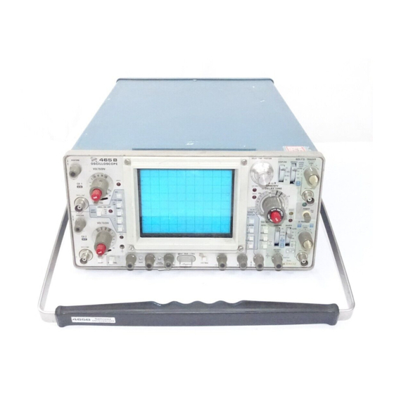
Tektronix 465B Instruction Manual
Dual channel four trace portable oscilloscope
Hide thumbs
Also See for 465B:
- Instruction manual (291 pages) ,
- Instruction manual (144 pages) ,
- Instruction manual (54 pages)
Table of Contents
Advertisement
Quick Links
Advertisement
Table of Contents
Troubleshooting


Need help?
Do you have a question about the 465B and is the answer not in the manual?
Questions and answers