Sign In
Upload
Manuals
Brands
Tektronix Manuals
Test Equipment
465B
Tektronix 465B Manuals
Manuals and User Guides for Tektronix 465B. We have
5
Tektronix 465B manuals available for free PDF download: Instruction Manual
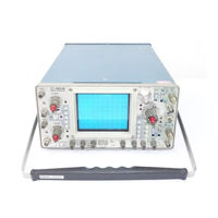
Tektronix 465B Instruction Manual (292 pages)
dual channel four trace portable oscilloscope
Brand:
Tektronix
| Category:
Test Equipment
| Size: 49 MB
Table of Contents
Table of Contents
3
List of Illustrations
8
List of Tables
10
Operators Safety Summary
11
Precautions
12
Servicing Safety Summary
13
Product View
14
Specifications
15
Electrical Characteristics
15
Environmental Characteristics
25
Physical Characteristics
26
Operating Instructions
27
Installation
27
Line Voltage Selection
27
Power Cord Conductor Identification
27
Regulating Range Selection
28
Controls, Connectors and Indicators
29
Vertical
29
Fuse Selection
29
Instrument Cooling
29
Display and Calibrator
30
Trigger - a and B Where Applicable
31
Horizontal and Power
33
Rear Panel
34
Basic Oscilloscope Displays
35
Left Side Panel
35
Right Side Panel
35
Preset Instrument Controls
36
Magnified Sweep Display
36
Normal Sweep Display
36
Delayed Sweep Display
36
Alternate Sweep Display
37
Single Sweep Display
37
X-Y Display
37
Rackmounting
38
Dimensions
38
Slide-Out Tracks
38
Dimensional Drawing
39
Slide-Out Track Assemblies
41
Hardware Needed to Mount the Instrument in the Cabinet Rack
41
Mounting Procedure
42
Installing the Support Block on the Instrument
42
Rear Support Kit View
42
Methods of Mounting the Stationary Section to the Front Rails
43
Locating the Mounting Holes for the Left Stationary Section
44
Supporting the Rear Stationary Sections
45
To Insert the Instrument
46
To Remove the Instrument
46
Alternative Rear Mounting Methods
47
Removing or Installing the Instrument
47
Slide-Out Track Lubrication
47
To Adjust Alignment
47
Method of Installing the Instrument Using Rear Support Brackets
48
Theory of Operation
49
Integrated Circuit Descriptions
49
Digital Logic Conventions
49
Basic Block Diagram of the Oscilloscope
49
General Description
50
Linear Devices
50
Detailed Description
52
Channel 1 Preamp
52
Input Coupling
52
Input Attenuator
53
Source Follower
53
First Amplifier
53
Channel 2 Preamp
54
Vertical Switching Logic
54
Second Amplifier
54
Diode Gates
54
Channel 1 Display Only
56
Channel 2 Display Only
56
A Trigger View/Add Vertical Mode/X-Y Mode
56
Chop Clock and Alternate Logic
56
Vertical Mode Switch
57
Alternate Trace Sync
57
Chopped Blanking Amplifier
57
Delay-Line Driver/Normal Trigger Pickoff Amplifier
57
Vertical Output Amplifier
58
Exclusive-NOR Switching Circuit
58
Scale-Factor Switching Circuit
58
Delay Line/Input Amplifier/Trace Separation
58
A and B Trigger Generators
59
Output Amplifier
59
Trigger Source
59
Trigger Coupling
59
Sweep and Z Axis Logic Circuit
60
Input Source Follower
60
Tunnel Diode Driver
60
A Sweep Gate
60
B Sweep Gate
61
Sweep Control Integrated Circuit
61
Holdoff Timing
61
A Sweep Holdoff Amplifier
63
B Sweep Holdoff Amplifier
63
A Sweep Z-Axis Gate/B Sweep Z-Axis Gate
63
A +Gate and B +Gate Emitter Followers
63
A and B Sweep Generators
64
Horiz Alt Sync Pulse Amplifier
64
Disconnect Amplifier
64
Sawtooth Generator
65
A Sweep Start Comparator
65
A Sweep End of Sweep Comparator
65
B Sweep Generator Differences
65
Horizontal Display Logic
66
Horizontal Amplifier
66
Vert Alt Sync Pulse
66
A and B Sweep Switching
66
X-Axis Amplifier
67
Input Paraphase Amplifier
67
Gain Setting Cascode Amplifier
67
CRT Circuit
68
High-Voltage Oscillator
68
High-Voltage Regulator
68
High-Voltage Rectifier and Output
69
CRT Control Circuits
70
Z-Axis Amplifier
70
DC Restorer
70
Sinusoidal Sample Voltage at Center Tap of T4015
71
Calibrator
72
Multivibrator
72
Low-Voltage Power Supply
73
Calibrator Circuit Waveform Diagram
73
Block Diagram of the Low-Voltage Power Supply Circuit
74
Fan Motor Circuit
75
Power Input
75
Secondary Circuit
75
Calibration Procedure
76
Test Equipment Required for Calibration
76
Performance Check
79
Index to Performance Check Procedure
80
Calibration: Vertical
81
The Instrument Control Settings
81
Check Trace Rotation
81
Check ALT Mode
81
Check CHOP Mode
82
Check CH 1 Balance
82
Check CH 2 Balance
82
Check Vertical Position Range and Centering
82
Deflection Factor Limits
83
Check Beam Find Operation
83
Check CH 1 and CH 2 Deflection Factor
83
Check Ch 1 and CH 2 VAR VOLTS/DIV Range/Check ADD Mode
83
Check Invert Mode
84
Check Vertical Low-Frequency Compensation
84
Check CH 1 and CH 2 Volts/Division Compensation
84
Check CH 1 and CH 2 Transient Response
84
Check CH 1 and CH 2 Bandwidth
85
Check Cascaded Gain and Bandwidth
85
Check Trigger View Centering and Gain
85
Check Trigger View Low-Frequency Compensation
86
Check Trigger View High-Frequency Compensation
86
Check Zero Trigger View Delay
86
Calibration: Triggers
87
Check a and B Internal Triggering
87
Check a and B External Triggering
88
Check a NORM TRIG Mode
88
Check SINGL SWP TRIG Mode
88
Calibration: Horizontal
90
Check a and B Time/DIV Accuracy
90
Check a VAR Time/DIV Range
91
Check Delay or Differential Time Linearity
91
Check Delay or Differential Time Accuracy
91
Check Delay or Differential Jitter
92
Check ALT Horizontal Display Trace Separation
92
Check a INTEN and B ENDS a Operation
92
Check X Gain
93
Check X Bandwidth
93
Adjustment Procedure
94
Limits and Tolerances
94
Calibration Equipment Altenatives and Partial Procedures
94
Interactions
94
Adjustment Interactions Chart
95
Index to Adjustment Procedure
96
Preparation to Adjustment
96
Power Supply Adjustment
98
Check/Adjust Power Supply DC Levels, Regulation and Ripple
98
Check High Voltage Supply
99
Low Voltage Power Supply Limits
99
Typical Low Voltage Power Supply Ripple
99
Display and Z Axis Adjustment
100
Check/Adjust CRT Grid Bias
100
Check/Adjust Trace Alignment - Trace Rotation
100
Check/Adjust Y-Axis Alignment
101
Check/Adjust Geometry
101
Check/Adjust Z-Axis Compensation
101
Vertical Adjustment
102
Check Probe Indicator LED
103
Check Input Coupling (AC-GND-DC) Switches
103
Check Beam Find
103
Check/Adjust CH 1 Var Volts/DIV Balance and Var Indicator
104
Check/Adjust CH 1 Position Centering
104
Check/Adjust CH 2 Var Volts/DIV Balance and Var Indicator
104
Check/Adjust CH 2 Invert Balance/Check/Adjust CH 2 Position Centering
104
Check CH 2 and CH 1 Gate Current
105
Check/Adjust Gain
105
Vertical Deflection Accuracy
105
Check CH 1 and CH 2 Var Volts/DIV Range
106
Check ADD Mode
106
Check Compression and Expansion
106
Check/Adjust Low-Frequency Compensation
107
Maximum Overshoot or Rounding
107
Vertical Output Low-Frequency Compensation
107
CH 1 Low-Frequency Compensation
108
CH 2 Low-Frequency Compensation
108
Check/Adjust CH 1 Volts/DIV Compensation
109
Adjust CH 2 Volts/DIV Compensation
109
Check/Adjust CH 2 and Output High-Frequency Compensation
110
Check CH 2 Position Effect
110
Check/Adjust CH 1 High-Frequency Compensation
111
Check CH 1 Position Effect
111
Check CH 2 Transient Response
111
Check Bandwidth
111
Check Channel Isolation
112
Check/Adjust Common-Mode Rejection Ratio
112
Check Bandwidth Limit Operation
113
Check/Adjust Trigger View Centering and Gain
113
Check/Adjust Trigger View Low-Frequency Compensation
113
Check/Adjust Trigger View High-Frequency Compensation
114
Check/Adjust Zero Trigger View Delay
114
Triggers Adjustment
115
Check/Adjust a Trigger Sensitivity and TRIG LED
115
Check/Adjust B Trigger Sensitivity
116
Check/Adjust B Trigger Slope Center and Level
117
Check/Adjust a Trigger Slope Center and Level
117
Check/Adjust a Trigger DC Levels
118
Check B Trigger DC Levels
118
Check B Internal 10 Mhz Triggering
118
Check a Internal 10 Mhz Triggering
119
Check a External 10 Mhz Triggering
119
Check B External 10 Mhz Triggering
120
Check B and a External 100 Mhz Triggering
120
Check a Internal 100 Mhz Triggering
121
Check B Internal 100 Mhz Tiggering
122
Check a and B High Frequency Reject Triggering
122
Check Single Sweep
122
Check 60 Hz Internal Triggering
123
Check 60 Hz External Triggering
124
Check a and B External Trigger Level Ranges
124
Check Line Triggers
125
Check NORM a Trigger Mode
125
Check Auto Recovery Time
126
Horizontal Adjustment
127
Check/Adjust Sweep Start and a Sweep Calibration
128
Check/Adjust Horizontal Amplifier Gain
128
Check Sweep Linearity
129
Check/Adjust R4253 Magnifier Centering and R4275 Registration
129
Check/Adjust B Sweep Calibration
129
Check a Sweep Length/Check Variable Time/Devision
129
Check Horizontal Position Range
130
Check/Adjust a 10 Μs Timing
130
Check/Adjust a Sweep High Speed Timing
130
Check/Adjust B Sweep High Speed Timing
131
Check a and B Time/Division Accuracy
131
Adjust High-Speed Magnified Timing
131
Check a and B Magnified Timing Accuracy
132
Check Delay or Differential Time Jitter
133
Check/Adjust X Gain
133
Check X-Y Phasing and Bandwidth
134
Check B Ends a
134
Check a Trigger Holdoff
134
Gates, Calibrator and EXT Z Axis Adjustments
136
Check a and B +Gates
136
Check/Adjust Calibrator DC Level
136
Check External Z Axis
137
Maintenance
138
Cabinet and Rack Adapter Removal and Replacement
138
Standard Cabinet Removal
138
Standard Cabinet Installation
138
Rack Adapter Removal
139
Rack Adapter Installation
139
Preventive Maintenance
140
Cleaning
140
Switch Contacts Care
140
Air Filter Care
141
Visual Inspection
141
Lubrication
141
Semiconductor Checks
141
Troubleshooting
142
Read-Only Memory U1605 Logic
144
Color Codes
145
Troubleshooting Techniques
146
Check Control Settings
146
Isolate Trouble to a Circuit
146
Check Voltages and Waveforms
146
Check Individual Components
147
Corrective Maintenance
148
Repair and Readjust the Circuit
148
Static-Sensitive Components
148
Relative Susceptibility to Static Discharge Damage
149
Component Removal and Replacement
150
Circuit Boards Removal and Replacement
150
Vertical Preamplifier Assembly Removal and Replacement
150
Vertical Mode Switch and Attenuators Removal and Replacement
151
Trigger Generator and Sweep Logic Board Removal and Replacement
151
Sweep Timing Circuit Board Removal and Replacement
152
Vertical Output Board Removal
152
Main Interface Board Removal
153
Power Transformer Removal and Replacement
155
Cathode Ray Tube (CRT) Removal and Replacement
155
High Voltage Multiplier Removal and Replacement
156
Transistors and Integrated Circuits Removal and Replacement
156
Interconnecting Pins Removal and Replacement
157
Ceramic Terminal Strips Removal and Replacement
158
Readjustment after Repair
158
Instrument Repackaging
158
Required Reshipment Information
158
Maintenance Aids
159
Suggested Troubleshooting Equipment
160
Options
161
Option 04 - EMC Environmental
162
Option 04 - Electrical
163
Option 04 - Mechanical
163
Option 05 - TV Sync Separator
164
Option 05 Specification
165
Option 05 - Furnished Accessories
165
Option 05 - Operating Information
165
Installation of Video Graticule
165
Operation of the Sync Separator
166
Triggering the Sweep
166
Vertical Operating Modes - Special Considerations
166
Single Channel Triggering
166
Add Mode
167
Selecting an Individual Line
167
One Frame Cycle/Two Frame Cycle
167
Overscanned Displays
167
Identifying Fields, Frames and Lines in 525/60 and 625/50 TV Systems
168
Horizontal Sync Pulse Measurement
168
RF Interference
168
NTSC (CCIR System M)/CCIR System B and Similar 625/50 Systems
168
Option 05: Theory of Operation
169
Trigger Pickoff
169
Option 05 Block Diagram
169
Trigger Amplifier and Inverter
170
Sync Separator
170
Option 05: Adjustment Procedure
171
Preliminary Procedure for Sync Separator Calibration
171
Option 05 Test Equipment Required
172
Preliminary Control Settings for Option 05 Calibration
172
Clipping Level Adjustment - R2826 on Sync Separator Board
172
A and B Sweep TV Line Trigger Check
173
A12 TV Sync Separator and Inverter Amplifier Board Component Locations
174
Option 05 465B Vertical Input Changes
174
Option 05 Trigger Switches and Trigger Pickoff
175
Option 05 TV Sync Separator and Inverter Amplifier
176
Option 05 - Electrical Parts
177
Option 05 - Mechanical Parts
179
Option 07: External DC Operation
180
Option 07: Controls and Connectors
180
Option 07: Operation and Inspection
180
Option 07: Theory of Operation
180
Turn-Off Level Circuit
181
Option 07 Block Diagram
181
Turn-Off Circuit
182
Start Circuit
182
465B Option 07 DC Inverter
182
Inverter Circuit
183
DC Input
183
465B Option 07 Primary Winding
183
Option 07: Maintenance
184
Option 07: Test Equipment Required
184
Start-Stop Switch
184
Power-Mode Switch - S1665
184
Option 07: Adjustment
185
Circuit Board Chassis Removal
185
Power Supply Alternatives
185
Inverter Balance
186
Turn-Off Level
186
Option 07 DC Inverter Circuit Boards Adjustment/Test Point Locations
187
Option 07 DC Inverter Idealized Waveforms
187
Option 07 DC Inverter Circuit Board Component Locations
188
Option 07: Electrical Parts
189
Option 07: Mechanical Parts
191
Option 07 Exploded View
192
Option 78: Type P11 Phosphor
193
Replaceable Electrical Parts
194
Cross Index - MFR. Code Number to Manufacturer
195
Semiconductor Lead Configurations
230
Diagrams and Circuit Board Illustrations
231
AC Waveforms
232
Test Oscilloscope Setup
233
DC Voltages
233
A1 Vertical Preamplifier Circuit Board Diagram
235
A5-Vertical Mode Switch Circuit Diagram
241
A2 Vertical Output Circuit Board Diagram
244
A7 Trigger Generator and Sweep Logic Circuit Board Diagram
248
A-4 Interface Circuit Board Diagram
249
A6-Timing Circuit Board Diagram
251
465B Control Settings
253
Vertical Preamplifier Circuit Board Adjustment Locations
265
A2 Vertical Output Amplifier Circuit Board Adjustment Locations
266
Vertical Output Amplifier Circuit Board Adjustment Locations
266
Trigger Generator and Sweep Logic Circuit Board Adjustment Locations
267
Timing Circuit Board Adjustment Locations
268
Replaceable Mechanical Parts
269
Indentation System
269
Item Name
269
Abbreviations
269
Mechanical Parts List
272
Exploded View
276
Accessories View
284
Manual Change Information
286
Calibration Test Equipment Replacement
287
Advertisement
Tektronix 465B Instruction Manual (291 pages)
Brand:
Tektronix
| Category:
Test Equipment
| Size: 6 MB
Table of Contents
Table of Contents
3
Installation
8
Vertical
8
Trigger
8
Rear Panel
8
Of Tables List
10
Introduction
15
Electrical Characteristics
15
Introduction and Specification
21
Environmental Characteristics
25
Physical Characteristics
26
Preparation for Use
27
Line Voltage Selection
27
Regulating Range Selection
28
Instrument Cooling
29
Display and Calibrator
30
Horizontal and Power
33
Left Side Panel
35
Right Side Panel
35
Preset Instrument Controls
36
Normal Sweep Display
36
Magnified Sweep Display
36
Delayed Sweep Display
36
Slide-Out Tracks
38
Mounting Procedure
42
Section Organization
49
Integrated Circuit Descriptions
49
General Description
50
Detailed Description
52
Channel
52
Preamp
52
Channel 2 Preamp
54
Vertical Switching Logic
54
Vertical Mode Switch
57
Vertical Output Amplifier
58
Aandb Trigger Generators
59
Sweep Andz Axis Logic Circuit
60
Aand Bsweep Generators
64
Horizontal Display Logic
66
Horizontal Amplifier
66
Crt Circuit
68
Calibrator
72
Low-Voltage Power Supply
73
Regulating Range
74
Fan Motor Circuit
75
Introduction
76
Test Equipment Required
76
Performance Check
79
Index to Performance Check Procedure
80
Delay or Differential Time Accuracy
80
Vertical
81
Low-Frequency Compensation
84
Triggers
87
Horizontal
90
Aandb Timing Accuracy
90
Adjustment Procedure
94
Index to Adjustment Procedure
96
Power Supply
98
Display and Zaxis
100
Vertical
102
Specification
94
Vertical Deflection Accuracy
105
Maximum Overshoot or Rounding
107
Triggers
115
Horizontal
127
Gates, Calibrator, and Ext Zaxis
136
Introduction
138
Preventive Maintenance
140
Introduction
140
Cleaning
140
Visual Inspection
141
Lubrication
141
Semiconductor Checks
141
Readjustment
141
Troubleshooting
142
Troubleshooting Aids
142
Read-Only Memory U1605 Logic
144
Troubleshooting Equipment
146
Troubleshooting Techniques
146
Corrective Maintenance
148
Obtaining Replacement Parts
149
Soldering Techniques
149
Component Removal and Replacement
150
Readjustment after Repair
158
Instrument Repackaging
158
Maintenance Aids
159
Suggested Troubleshooting Equipment
160
General Option Information
161
Introduction
162
Options
161
Option 05 Tv Sync Separator
164
Introduction
164
Specification 6
165
Furnished Accessories
165
Test Equipment Required
172
Tektronix 465B Instruction Manual (144 pages)
Digital Multimeter
Brand:
Tektronix
| Category:
Test Equipment
| Size: 3 MB
Table of Contents
Table of Contents
3
List of Illustrations
6
Safety Summary
7
Before Operating
11
Introduction
11
Operating Safety
12
Line Voltage Selection
12
Regulating Range Selection
13
Instrument Cooling
13
Controls,Connectors,Andindicators
14
Vertical
14
Display and Calibrator
16
Dm44 Option
18
Trigger
20
Horizontal and Power
23
Rear Panel
26
Left Side Panel
28
Right Side Panel
28
Basic Oscilloscope Displays
29
Preliminary
29
Preset Instrument Controls
30
Normal Sweep Display
31
Magnified Sweep Display
32
Delayed Sweep Display
32
Alternate Sweep Display
33
Y Display
34
Single Sweep Display
35
Dm44 Displays and Measurements
36
Resistance
36
Volts
38
Temperature
40
Temperature Accuracy Checks
42
Adjustments and Measurements
44
Operating Considerations
44
Graticule
44
Grounding
44
Signal Connections
45
Probe Compensation
45
Input Coupling Capacitor Precharging
46
Operator's Checks and Adjustments
47
Trace Rotation Adjustment
47
Basic 465B Timing Check
47
Dm44 Timing Check
49
A Trigger Input Coupling Check
50
External Horizontal Gain Check
50
Making Precision Measurements
51
Ac Peak-To-Peak Voltage
51
Instantaneous DC Voltage
52
Algebraic Addition
53
Common-Mode Rejection
55
Amplitude Comparison
56
Time Duration
57
Frequency
58
Rise Time
58
Time Difference between Two Time-Related Pulses
60
Time Comparison
61
Phase Difference
62
High Resolution Phase Difference
64
Pulse Jitter
65
Delayed Sweep Magnification
65
Magnified Sweep Starts after Delay
66
Triggered Delay Sweep Magnification
67
Basic 465B Delayed Sweep Time
68
Measurements
68
Time Duration (Basic 465B)
68
Frequency (Basic 465B)
70
Rise Time (Basic 465B)
70
Time Difference between Repetitive Pulses (Basic 465B)
71
Time Difference between Two Time-Related Pulses (Basic 465B)
73
Dm44 Delayed Sweep Time
74
Measurements
74
Time Duration Using DM44
78
Frequency Using DM44
79
Rise Time Using DM44
79
Time Difference between Repetitive Pulses Using DM44
80
Time Difference between Two Time-Related Pulses Using DM44
82
Specification
84
Vertical System
84
Trigger System
89
Horizontal Deflection System
91
Calibrator
95
Z-Axis Input
96
Signal Outputs
96
Power Source
97
Cathode-Ray Tube
98
Dm44
98
Accessories
105
Standard Accessories Included
105
Optional Accessories
105
Options
106
General Description
106
Option 01
106
Option 04
106
Option 05
106
Option 07
107
Option 05 Tv Sync Separator
108
General Information
108
Specification
109
Option 05 Accessories
110
Operating Information
110
Installation of Video Graticule
110
Operation of the Sync Separator
111
Triggering the Sweep
112
Vertical Operating Modes-Special Considerations
112
Typical Operation
113
Selecting an Individual Line
114
Special Measurements
115
Identifying Fields, Frames and Lines
115
In 525/60 and 625/50 Tv Systems
115
NTSC (CCIR System M)
115
CCI R System B and Similar 625/50 Systems (Including PAL)
116
Option 07 External DC Operation
117
Specification
117
Controls and Connectors
117
Optional Accessory
118
Operating Information
118
Advertisement
Tektronix 465B Instruction Manual (148 pages)
OSCILLOSCOPE AND DIGITAL MULTIMETER
Brand:
Tektronix
| Category:
Test Equipment
| Size: 3 MB
Table of Contents
Safety Summary
4
Before Operating
7
Horizontal and Power
17
Single Sweep Display
29
Temperature Accuracy Checks
36
Time Difference between Two
54
Tektronix 465B Instruction Manual (54 pages)
OSCILLOSCOPE WITH OPTIONS
Brand:
Tektronix
| Category:
Test Equipment
| Size: 3 MB
Table of Contents
Table of Contents
22
Horizontal and Rear Panel
25
Vertical
25
Trigger
25
Ower
25
Dimensions
25
Methods
25
Ogic
25
Circuit
25
Procedure
25
Horizontal
25
Vertical
26
Sync Separator
26
Low-Voltage Power Supply
27
Adjustment Interaction
27
List
27
Ist
27
Riggers
28
Option 04
28
Trigger Amplifier
28
Warranty
31
Ta Ble of
32
Ble of Co N Ten
33
TA BLE O FCO N TEN TS (Cont)
33
Identifying F Ields, Frames, and
34
List
35
Preset Instrument Controls
36
Agnified Sweep Display
36
Delayed Sweep Display
36
Specification
39
Controls and Connectors
39
Ext Ernal DC O Peratio N
39
DC Input
39
Specification
42
Controls, Connectors, and Indicators
42
Index to Performance Check
42
Operation
42
Test Equipment Required
43
Limits and Tolerances
43
Preventive Maintenance
43
Troubleshooting
43
Troubleshooting Aids
43
Corrective Maintenance
43
Obtaining Replacement Parts
43
Maintenance
43
Electrical Parts List
43
Mechanical Parts List
43
Maintenance Precautions
49
Removing or
49
Cabinet Removal
49
Readout Display
54
Advertisement
Related Products
Tektronix 465M
Tektronix 465
Tektronix 460
Tektronix 466
Tektronix 464
Tektronix 468
Tektronix 4691
Tektronix 465 QB
Tektronix 454A
Tektronix 432
Tektronix Categories
Test Equipment
Measuring Instruments
Amplifier
Portable Generator
Printer
More Tektronix Manuals
Login
Sign In
OR
Sign in with Facebook
Sign in with Google
Upload manual
Upload from disk
Upload from URL