Table of Contents
Advertisement
Quick Links
Optical Wavelength Laboratories
OPERATIONS GUIDE
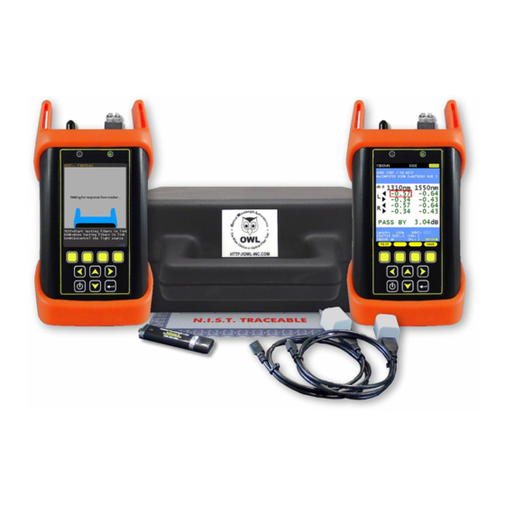
FIBER OWL 7 SERIES BI-DIRECTIONAL CERTIFIERS
MODEL #s:
F7BMS (MM / SM)
F7BMX (MM only)
F7BMV (MM / VFL)
F7BSX (SM only)
F7BSV (SM / VFL)
OWL
Optical Wavelength Laboratories (OWL)
N9623 Old Hwy 12
Whitewater, WI 53190
Phone: 262-473-0643
Internet: http://OWL-inc.com
Revision 1.0b
Advertisement
Table of Contents


Need help?
Do you have a question about the F7BMS MM and is the answer not in the manual?
Questions and answers