Table of Contents
Advertisement
Advertisement
Table of Contents

Related Manuals for HELIX P SIX DSP MK2


Summary of Contents for HELIX P SIX DSP MK2
- Page 1 P SIX DSP 6-Kanal Verstärker mit integriertem DSP...
-
Page 2: General Instructions
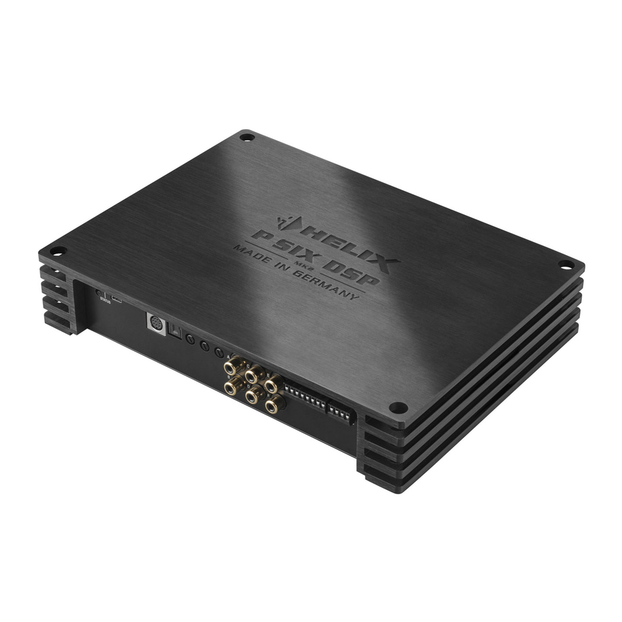
HELIX dealer. ble cross-section for the connection of HELIX Install your HELIX P SIX DSP MK2 in a dry loca- P SIX DSP MK2. The fuses may only be replaced by identically rated fuses (3 x 25 A) to avoid to a solid mounting surface using proper mount- ing hardware. - Page 3 DSP and which setup has been chosen. al stereo signals. USB Input Line Input Connects the HELIX P SIX DSP MK2 to your nals. Control Input Highlevel Input Multifunction interface for e.g. an optional re- Highlevel speaker inputs for connecting a mote control or other HELIX accessory.
-
Page 4: Initial Start-Up And Functions
Green means that setup 1 is load ed, orange Attention: It is mandatory to properly adapt the in- put sensitivity of the P SIX DSP MK2 to the signal dicates that no setup is loaded. In that case please load a new setup via the DSP PC-Tool software. -
Page 5: Line Output
We strongly recommend to use this output for turn- function if the device is fed with digital input signals. to the Line Outputs of the HELIX P SIX DSP MK2. If this LED lights up reduce the input sensitivity by using the potentiometers until the LED goes out. -
Page 6: Installation
Installation Connection of HELIX P SIX DSP MK2 to the head max.). It is not mandatory to use all speaker unit/car radio: inputs. Make sure that the polarity is correct. If one or more connections have reversed polarity Caution: Carrying out the following steps will re- quire special tools and technical knowledge. - Page 7 Installation Source Which input? Position Position Potentiome- Jumper A Jumper B ter position 4-channel OEM radio Highlevel A-D Optional Max. CCW Up to 25 Watts RMS power each channel position Highlevel A-D Optional Max. CCW Up to 100 Watts RMS power each channel position Highlevel A-F Max.
- Page 8 Follow the subsequent steps if you like to per- about the volume level. Keep in mind that this will lead to full level on the outputs of the HELIX your audio source by using the potentiometers: This may cause severe damage to your speak- speakers to the outputs of the HELIX ers.
- Page 9 Installation Information: The HELIX P SIX DSP MK2 can +12 V / +24 V wire) should be connected to a only handle uncompressed digital stereo sig- common ground reference point (this is locat- ed where the negative terminal of the battery is...
- Page 10 Easy Plug Cable. You may need To simplify installation to an OEM or aftermar- ket radio the HELIX P SIX DSP MK2 can also be a special ISO-adaptor depending on vehicle connected using the optional Easy Plug Cable type.
- Page 11 Caution: We strongly recommend not to connect 1. Download the DSP PC-Tool software from the puts of the HELIX P SIX DSP MK2 before the basic 2. Install the software on your computer. During Ignoring this advice may result in damaging the...
- Page 12 P SIX DSP MK2 by inserting an optional HELIX P SIX DSP MK2 and replace it by the new side pan- Extension Card (HEC) - for example a Bluetooth ®...
- Page 13 Ready for 24 V voltage even if the battery’s voltage drops to 6 Volts It is possible to operate the P SIX DSP MK2 with a during engine crank. supply voltage of 12 Volts or 24 Volts (e.g. as usual...
-
Page 14: Technical Data
Technical Data RMS power - Channel A - F @ 4 Ohms ..........120 Watts per channel ( 1% THD+N) - Channel C - F @ 2 Ohms ..........230 Watts per channel ( 1% THD+N) Inputs ................6 x RCA / Cinch 6 Highlevel speaker input 1 x Optical SPDIF (12 - 96 kHz) 1 x Remote In... - Page 15 Audiotec Fischer GmbH Hünegräben 26 · D-57392 Schmallenberg Tel.: +49 2972 9788 0 · Fax: +49 2972 9788 88...
Need help?
Do you have a question about the P SIX DSP MK2 and is the answer not in the manual?
Questions and answers