Table of Contents
Advertisement
Quick Links
Advertisement
Table of Contents

Related Manuals for Cybernet CyberMed M10 Series


Summary of Contents for Cybernet CyberMed M10 Series
- Page 1 CyberMed M10 Series User Guide...
- Page 2 Notes: Before using this information and the product it supports, be sure to read important Safety Information on page ii. Some instructions in this guide may assume that you are using Win 7/ Win 8.1. If you are using another Windows Operating System, some operations may be slightly different.
- Page 3 For this reason, we apologize for any omission you might find. Cybernet is always trying to improve the performance and reliability of its products. For that reason, the hardware and software components shown within the user guide might not perfectly match those of your system.
- Page 4 FCC-B Radio Frequency Interference Statement This equipment has been tested and found to comply with the limits for a class B digital device, pursuant to part 15 of the FCC rules. These limits are designed to provide reasonable protection against harmful interference in a residential installation.
-
Page 5: Safety Instructions
Safety Instructions Always read the safety instructions carefully. Keep this equipment away from humidity. Lay this equipment on a reliable flat surface before setting it up. The openings on the enclosure are for air convection hence protect the equipment from overheating. DO NOT COVER THE OPENINGS. Confirm the voltage of the power source and adjust accordingly to 110/220V before connecting the equipment to the power inlet. - Page 6 WEEE Statement (Waste Electrical and Electronic Equipment) The WEEE directive places an obligation on EU-based manufacturers, distributors, retailers and importers to take-back electronics products at the end of their useful life. A sister Directive, ROHS (Restriction of Hazardous Substances) compliments the WEEE Directive by banning the presence of specific hazardous substances in the products at the design phase.
-
Page 7: Table Of Contents
Contents FCC-B Radio…………………….……………..……………….…..…..i Introduction……………………………….………………..………...1 CyberMed M10 Specifications…………...……………………..1 Intended Use……………………...……...…………………….…3 Power Management…………………………………...…..……..7 Energy Saving Tips………………………………………………10 Over View………………………………...….………………11 R e a r V i e w … … … … … … … … … … … . . . … … … … … … … . 1 2 D i m e n s i o n …... -
Page 8: Introduction
Introduction Congratulations for purchasing the M10 Series. The CyberMed M10 Series is your best Slim LCD PC choice. With the fantastic appearance and small form factor, it can easily be set anywhere. The feature packed platform also gives you an exciting PC experience. - Page 9 Touch Screen True flat projected capacitive 2F touch. Optional True flat resistive touch available base on project basis Webcam Optional 2.0 Megapixel Camera Expansion Slot One half size mini-PCIe for WiFi Wireless Optional 802.11 b/g/n + Bluetooth or 802.11 a/b/g/n +Bluetooth Bottom I/O Panel 1 Power Switch;...
-
Page 10: Intended Use
OS Support Windows 7, POSReady 7, Windows 8.1, Linux Dust & Waterproof IP54 (Front Panel) Intended use The M10 Series is designed for general pc application purpose for hospital environment and for diagnosis. It could be used for Radiology, PACS (Picture Archiving Communication Systems), LIS (Lab Information Systems) and Electronic Medical Record purpose. - Page 11 4. Before suspending the unit, make sure the material usedfor suspension is sturdy and stable. If not properly suspended, the LCD PC unit may fall and causeserious injury to people standing nearby as well as to theunit itself. 5. If the user wishes to mount the LCD PC unit, rememberto use only the mounting hardware recommended by themanufacturer.
- Page 12 Various Factors of Environment 1. Operating Temperature: 0°C to 35°C; Non-operating temperature: -20°C to 60°C. 2. Operating Humidity (Non-Condensing): 20% to 85%. Non-operating Humidity (Non-condensing): 10% to 90%. 3. Do not insert objects into the openings. 4. Do not have liquids seep into the internal areas of the LCD PC unit. 5.
- Page 13 Servicing, Repairing, Maintenance & Safety Checks 1. If the unit is not functioning properly, observe theperformance level of the LCD PC closely todetermine what type of servicing is needed. 2. Do not attempt to repair the LCD PC unit on yourown. Disassembling the cover exposes users’...
-
Page 14: Power Management
ISO 7000-0434: Caution, consult ACCOMPANYING DOCUMENTS. ISO 7000-1641: Follow operating instructions or Consult instructions for use. IEC 60417 -5009: ready to use. IEC 60417-5031: Direct current. EU-wide legislation, as implemented in each Member State, requires that waste electrical and electronic products carrying the mark (left) must be disposed of separately from normal household waste. - Page 15 Power Management in Windows OS [Power Options] in Windows OS allow you to control the power management features of your display and hard drive. Go to [Start] > [Control Panel]. Then click on the [Power Options] link. M10 Series Power Management Page 8...
- Page 16 Select a power plan that suits your personal needs. You may also fine-tune the settings by clicking [Change plan settings]. The Shut down LCD-PC Menu presents the options of Sleep (S3) & Shut Down (S5) for rapid and easy management of your system power. M10 Series Power Management Page 9...
-
Page 17: Energy Saving Tips
Power Management through ENERGY STAR qualified Monitors (Not supply with the LCD PC) The power management feature allows the LCD-PC to initiate a low-power or “Sleep” mode after a period of user inactivity. When used with an external ENERGY STAR qualified Monitor, this feature also supports similar power management features of the monitor. -
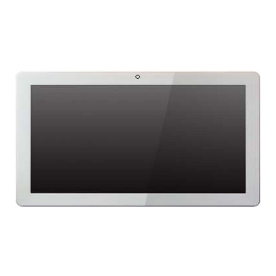
Page 18: Over View
CyberMed M10 Series Overview Figure 1: Front View with Optional Webcam and Side View Item No. Description Touch screen Built‐in web cam Ventilation Optional MSR cable hole M10 Series User Guide Page 11... -
Page 19: Rear View
Figure 2: Rear View Item No. Description VESA mounting holes Cable cover Power button Figure 3: Bottom I/O View Item No. Description Power button DC Jack 19V COM3 USB2 COM1~COM2(from right to left) USB 2.0 (x4) (two optional USB) i Audio Jack for Mic‐IN and Line‐Out M10 Series User Guide Page 12... -
Page 20: Optional Device Box
Figure 4: Dimension Figure 5: Optional Device Box(with USB cables attached) M10 Series User Guide Page 13... -
Page 21: Front View And Top View
Figure 6: Front View and Top View of Device Box Number Description Line-Out Mic-IN Card Reader Scanner RFID Figure 7: Dimension of Device Box M10 Series User Guide Page 14... -
Page 22: System Assembly
System Assembly This chapter provides system assembly information and procedures. While performing any installation, use a grounded wrist strap before handling computer components and carefullyfollow all installation procedures. Static electricity may damage the components. This chapter will include instructions for how to install CPU, heat sink, memory modules, hard disk drive (HDD), optical disk drive (ODD), mini-PCIE card. - Page 23 M10 Series Disassembly ORIENTATION: Presumes the top of the LCD PC is away from you and the bottom or I/O controller board is nearest you. Do not put any pressure on the LCD PC to avoid adding pressure to the System or place any equipment/device on top of it during assembly/disassembly.
- Page 24 Memory Module DDR3L SO-DIMM replacement 1. The memory module has only one notch And will only fit in the slot one way. 2. Flip the ejector clips outward to remove the memory module from the memory slot. 3. Insert the memory module into the DIMM Slot at a 45° angle.
- Page 25 Hard Disk Drive Replacement Loosen the two screws to remove the HDD bracket from the System. The HDD is secured by the bracket. Remove the two screws to release the bracket to replace the HDD. Optional MSR installation Insert the MSR module in place and fasten the two screws on the Side to secure the module Connect the MSR cable to the USB situated on the bottom I/O of the System.
-
Page 26: M O T H E R B O A R D L A Y O U
Motherboard Layout M10 Series User Guide Page 19... - Page 27 Connectors & Functions Connector Function Front I/O board Inverter connector LVDS connector System FAN connector LPT port connector Speaker & MIC connector 40pin external connector CN10 HDD LED connector CN11 Power LED connector CN12 SATA power connector CN13/14 USB port (internal) CN15 PS2 keyboard connector CN17 MSR connector CN18 COM5 (touch) connector CN19 Wide Range CN20 Power button (internal)
-
Page 28: Jumper Setting
Jumper Setting Inverter Selection Function 1 3 ▲LED 2 4 1 3 CCFL 2 4 COM1/COM2/COM3 Power Setting COM1, COM2 and COM3 can be set to provide power to your serial device. The voltage can be set to +5V or +12V in the BIOS. 1. Power on the system, and press the <DEL> key when the system is booting up to enter the BIOS Setup utility. 2. Select the Advanced tab. 3. Select VGA/COM Power Configuration Ports and press <Enter> to go to display the available options. 4. To enable the power, select COM1 ,COM2 or COM3 Power setting and press <Enter>. Select Power and press <Enter>. Save the change by pressing F10. ▲ = Manufacturer Default Setting M10 Series User Guide Page 21... -
Page 29: E-Recycling
Cybernet e-recycling SOP Cybernet has an e-recycling program that is very easy to use. Just follow the steps Explained below or go to our website at www.cybernet.us 1. Request an RMA via phone, email or support request. 2. We will arrange a call tag to have the product picked up. Just have it packed and ready to ship.
Need help?
Do you have a question about the CyberMed M10 Series and is the answer not in the manual?
Questions and answers