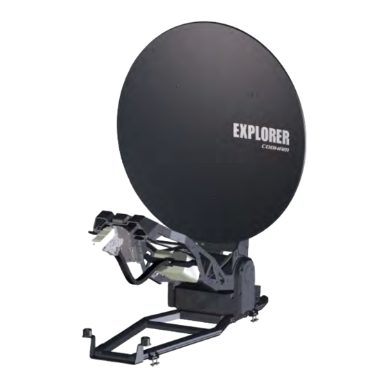
COBHAM EXPLORER 8100 User & Installation Manual
Drive-away vsat terminal
explorer 8000 series
Hide thumbs
Also See for EXPLORER 8100:
- User & installation manual (144 pages) ,
- Quick manual (2 pages) ,
- Quick manual (2 pages)
Table of Contents
Advertisement
Advertisement
Table of Contents

Related Manuals for COBHAM EXPLORER 8100


Summary of Contents for COBHAM EXPLORER 8100
- Page 1 EXPLORER 8000 series Drive-Away VSAT Terminal User & installation manual...
- Page 3 EXPLORER 8000 series Drive-Away VSAT Terminal User & installation manual Document number: 98-145510-E Release date: 8 June 2017...
- Page 4 Manuals issued by Thrane & Thrane A/S are periodically revised and updated. Anyone relying on this information should acquire the most current version e.g. from www.cobham.com/satcom, Cobham SYNC Partner Portal, or from the distributor.
-
Page 5: Safety Summary
Safety summary The following general safety precautions must be observed during all phases of operation, service and repair of this equipment. Failure to comply with these precautions or with specific warnings elsewhere in this manual violates safety standards of design, manufacture and intended use of the equipment, and will void the warranty. - Page 6 Service User access to the interior of the system units is not allowed. Only a technician authorized by Cobham SATCOM may perform service - failure to comply with this rule will void the warranty. Microwave radiation hazards During transmission the antenna radiates Microwave Power.This radiation may be hazardous to humans close to the antenna.
- Page 7 Product Variant General of radiation operators, short public area term EXPLORER 8100 Ku-band, 8 W BUC 30 m Ku-band, 20 W BUC 49 m 1200 mm Ku-band, no BUC Depends on BUC, see Figure 2 below Ka-band 36 m...
- Page 8 “Stay-clear area” shown below. Antenna clearance space [9.7] Ø2390 [94.1] Measures are in millimeter [inches in brackets]. Add a little extra security margin. Antenna clearance space [32.7] Ø2390 [94.1] Figure 3: Stay-clear area for the EXPLORER 8100 antenna 98-145510-E...
- Page 9 Mechanical “stay-clear” area, EXPLORER 8120 WARNING! Stay clear of the antenna when it is powered! The antenna dish can move quickly across a large area, and can cause injury to persons close to the antenna. When the antenna is powered, make sure nobody gets closer than the limits of the “Stay-clear area”...
-
Page 10: Table Of Contents
Table of contents Chapter 1 About this manual Manual overview ........................1-1 Precautions ..........................1-2 Chapter 2 Introduction EXPLORER 8000 series Drive-Away VSAT System ........2-1 Description of the system components ............. 2-3 Part numbers ......................... 2-10 Chapter 3 Installation To unpack the system ...................... - Page 11 Appendix D Command line interface Introduction ..........................D-1 Supported commands .....................D-3 Appendix E System messages Event messages – overview ..................E-1 Lists of events ......................... E-2 Appendix F Approvals EXPLORER 8100 ........................F-1 EXPLORER 8120 ........................F-6 Glossary ................................Glossary-1 Index ..................................Index-1 98-145510-E...
-
Page 12: About This Manual
1.1.1 Intended readers This is an installation and user manual for the EXPLORER 8100 and EXPLORER 8120 systems, intended for installers and users of the system. It is important that you observe all safety requirements listed in the beginning of this manual, and install and use the system according to the guidelines in this manual. -
Page 13: Precautions
Some materials can be dangerous. CAUTION! Do not use materials that are not equivalent to materials specified by Cobham SATCOM. Materials that are not equivalent can cause damage to the equipment. 98-145510-E Chapter 1: About this manual... -
Page 14: Introduction
The EXPLORER 8000 series is a series of drive-away VSAT antenna systems for vehicle roof mounting. It comes in the following versions: • EXPLORER 8100 (1 m reflector): • Ku Band with 8 W BUC • Ku Band with 20 W BUC •... - Page 15 The antenna provides a stable RF link and the modem provides services on the RF link. 2.1.2 Satellite service The EXPLORER 8100 operates in the Ku-band (10.7 to 14.5 GHz) or the Ka-band (Viasat eTRIA,19.7 to 30 GHz), depending on the EXPLORER 8100 model. The EXPLORER 8120 operates in the Ku-band (10.7 to 14.5 GHz).
-
Page 16: Description Of The System Components
Elevation drive Azimuth drive Connectors Manual stow and unfold access Figure 2: EXPLORER 8100 antenna system components, part 1 The location of the EXPLORER 8120 system components is the same as on the EXPLORER 8100 shown above. 98-145510-E Chapter 2: Introduction... - Page 17 GNSS antenna connecting cables are exposed on the Feed Support Structure. Reflector GNSS antenna Feed system Base frame Stow brackets with rubber bumpers Mounting brackets Figure 3: EXPLORER 8100 antenna system components, part 2 Reflector GNSS antenna Feed system Stow brackets with rubber bumpers Mounting brackets Base frame...
- Page 18 2.2.2 RF assembly The RF assembly varies depending on the antenna type. The following pages show the RF assemblies for EXPLORER 8100 Ku-Band, EXPLORER 8120 Ku-Band and EXPLORER 8100 Ka- Band. Ku-Band RF assembly The Ku version features a distributed RF system with a Block Up Converter (BUC) placed in the middle of the Feed support structure, connected to the Feed (Ortho Mode Transducer (OMT)/Low Noise Blockdown converter (LNB)) via a Flexible Wave Guide (FWG).
- Page 19 Description of the system components 2.2.3 Antenna Control Unit (ACU) The ACU manages all communication between the antenna and the connected modem. The ACU has status LEDs, a display and a keypad. It also provides a flexible configurable LAN interface (DHCP client/server, static IP address etc.) and a built-in web interface for configuration of the system.
- Page 20 Description of the system components 2.2.5 Web interface The VSAT system has a built-in web interface, which has two levels: • Mobile web interface, used for basic operations and status. Accessed from a smartphone or tablet. • Computer web interface, used for configuration, line-up, troubleshooting, extended status information etc.
- Page 21 2. Enter the IP address for the web interface. The default IP address is http://192.168.0.1. For details about further configuration and use, see Setup and operation on page 6-1. Figure 11: Web interface, DASHBOARD (example, EXPLORER 8100 Ku-Band) 98-145510-E Chapter 2: Introduction...
- Page 22 Description of the system components 2.2.6 LAN ports and WLAN The ACU has five configurable LAN connectors (type RJ45). LAN 2, LAN 3 and LAN 5 are switched, i.e. the configuration for LAN 5 also applies to LAN 2 and LAN 3. The default configuration is as follows: •...
-
Page 23: Part Numbers
System Control Unit, 500 W Antenna (Viasat eTria) Table 2-12: System part numbers for the EXPLORER 8100 systems Conversion kits The following conversion kits are available for the EXPLORER 8100 system: Part number Description 408157A-100 EXPLORER 8100 eTRIA Conversion Kit... - Page 24 Part numbers 2.3.2 EXPLORER 8120 system System part numbers The following EXPLORER 8120 system part numbers are available: Part number Description Antenna 408158A-50013 EXPLORER 8120 Ku VSAT EXPLORER Antenna EXPLORER 8120 Ku VSAT System Control Unit, 1000 W Antenna (No BUC) (No BUC, 1000 W ACU) 408158A-50211 EXPLORER 8120 Ku VSAT...
-
Page 25: Installation
Manual unfolding on page 7-11. Unpack the antenna and ACU and check that the following items are present: • EXPLORER 8100 Ku VSAT antenna (no BUC, 8 W BUC or 20 W BUC), or EXPLORER 8100 Ka VSAT antenna (Viasat eTRIA), or EXPLORER 8120 Ku VSAT antenna (no BUC, 8 W BUC or 20 W BUC) •... -
Page 26: To Install The Explorer 8000 Series
To install the EXPLORER 8000 series • With the antenna: • Cable harness, antenna to ACU and modem, 10 m (37-145530) • Hand crank for manual operation (62-147900) • Hex L key 4 X 142 mm for manual operation (covers and stow lock) (51-207294-000) •... - Page 27 To install the EXPLORER 8000 series Mechanical obstructions Make sure there are no objects on the vehicle that can obstruct the mechanical movement of the antenna. Preferably do not place any objects within the stay-clear area shown in page vi. If you cannot avoid objects inside the stay clear area, you must define a blocking zone.
- Page 28 To install the EXPLORER 8000 series The mounting frame of the antenna has lengthwise adjustable brackets to accommodate different placements of the supports. If you are not using a roof rack, omit the U-bars. Roof-rack mount We recommend a 3-bar solution over a 2-bar solution whenever possible. Adhere to the load limits of the roof-rack manufacturer and use sturdy, professional grade racks.
- Page 29 To install the EXPLORER 8000 series 3.2.4 Installation of the VSAT modem For a list of supported VSAT modems see VSAT modem unit on page 2-9. 1. Mount the VSAT modem close to the ACU, preferably at a distance less than 1 m. 2.
- Page 30 To install the EXPLORER 8000 series Ku-band, connections Figure 3: Ku-Band: Connection between antenna, ACU and VSAT modem If you replace antenna cables you must make a cable calibration. See Ku-Band Important version only: Cable calibration on page 6-22. Connect the cables as described below: The cables 6, 7, 8 and 14 are delivered as a cable bundle.
- Page 31 To install the EXPLORER 8000 series 12.Use LAN1 to access the web interface. 13.For LAN2, LAN3 and LAN4, see To configure the LAN network on page 6-14. 14.Connect ODU Comm. on the antenna pedestal to ODU Comm. on the ACU Ka-band, connections Figure 4: Ka-Band: Connection between antenna, ACU and VSAT modem Connect the cables as described below:...
-
Page 32: Interfaces Of The Antenna Control Unit (Acu)
Chapter 4 Interfaces This chapter is organized in the following sections: • Interfaces of the Antenna Control Unit (ACU) • Interfaces of the antenna • Interfaces of the VSAT modem Interfaces of the Antenna Control Unit (ACU) 4.1.1 WLAN interface The ACU has a WLAN interface for wireless access to the system. - Page 33 Interfaces of the Antenna Control Unit (ACU) 4.1.4 AC Input connector Provide AC power to the ACU from a standard 100-240 VAC supply using the cable included in the delivery. First find a suitable connector for your AC Mains supply and mount it on the cable according to the table below.
- Page 34 Interfaces of the Antenna Control Unit (ACU) 4.1.5 Connectors for antenna connection A cable bundle with all necessary cables between antenna and ACU is delivered with the system. There are 5 connectors on the ACU for connection to the antenna: •...
- Page 35 Interfaces of the Antenna Control Unit (ACU) • BUC Power & Comm.: GTC C4 female connector. Outline Pin function Wire color (on the ACU) BUC Power Black/Red BUC Power Rtn Black/White BUC Serial RX- BUC Serial RX+ Orange BUC Serial TX- Yellow BUC Serial TX+ Green...
- Page 36 Interfaces of the Antenna Control Unit (ACU) 4.1.7 RS-232 and RS-422 connectors for VSAT modem Use these connectors to connect the ACU to the VSAT modems with serial interfaces. See Appendix C, VSAT modem settings. RS-232 Outline (on the ACU) Pin function Not connected Ground...
- Page 37 Interfaces of the Antenna Control Unit (ACU) 4.1.8 LAN connectors The LAN connectors on the ACU are used for system setup and for connection to the VSAT modem. These connectors are normally only for communication within the VSAT system, Note not for connection to the Internet.
- Page 38 The User I/O connector is an 8-pin circular connector for user inputs and outputs, such as muting the antenna or signalling Rx lock. A short cable with a mating connector is available from Cobham SATCOM (part number S- 37-146760). Pinout and functions...
-
Page 39: Interfaces Of The Antenna
Interfaces of the antenna Interfaces of the antenna 4.2.1 VSAT air interface The antenna operates in the Ku-band (10.7 to 14.5 GHz) or the Ka-band (19.2 to 30 GHz). Service capabilities are determined by the connected VSAT modem. 4.2.2 GNSS air interface The antenna has a GNSS receiver for positioning input from the Positioning system. - Page 40 Interfaces of the antenna The connectors on the front of the antenna are partially hidden behind the reflector as shown. Pol-unit BUC-TX BUC M&C GNSS Figure 14: Connectors on the front of the antenna • Pol-unit. GTC C4 female connector for connecting to the Pol-unit. •...
-
Page 41: Interfaces Of The Vsat Modem
Interfaces of the VSAT modem • GNSS: SMA connector for input from the GNSS receiver • LNB: SMA connector for input from the LNB (Ku) or input/output for eTRIA (Ka) 4.2.5 Emergency stop button The antenna has a emergency stop button for service purposes or emergency stop. In normal operation the switch is on. -
Page 42: Initial Setup And Basic Functions
Chapter 5 Initial setup and basic functions This chapter describes the initial setup and basic functions of the EXPLORER 8000 series VSAT systems. For information on configuration with the web interface and how to use the display and keypad, see Setup and operation on page 6-1. This chapter has the following sections: •... - Page 43 Prerequisites for installation If you cannot avoid obstacles, you must define a blocking zone to make sure the equipment is not damaged. See Blocking zones on page 6-11. Unexpected antenna movements The movements of the antenna can be very powerful and hazardous to human beings. For this reason, the antenna has a safety feature that prevents or limits unexpected movements of the antenna, e.g.
-
Page 44: Initial Setup
Initial setup Initial setup After you have installed and connected the antenna, ACU and modem, you must make some initial configuration in the web interface before you can use the system. Go through the following steps to set up your VSAT system: 1. - Page 45 Start up and basic functions 2. Wait until the Power LED and the Fail/Pass LED on the ACU light steady green and the display shows Not ready: Not deployed. Then you can deploy the antenna. To deploy and stow the antenna you can use the keypad and display on the ACU, a smartphone or tablet, or a PC and the built-in web interface.
- Page 46 Start up and basic functions When the modem is ready, you can use it to connect to the Internet via the VSAT satellite system. To deploy the antenna using the web interface 1. Connect a PC to the LAN1 or front LAN connector at the ACU. You may also use WLAN, if it is configured.
- Page 47 Start up and basic functions 3. Check that the status shows STOPPED. 4. To start the antenna again, select OPERATION > START. The antenna restarts. Select OPERATION > DEPLOY when you are ready to continue. To stop the antenna using the mobile web interface 1.
- Page 48 Start up and basic functions To learn how to use the keypad see Keypad and display menus on page 6-27. You can also stow the antenna using the display menu system. To stow the antenna using mobile web interface 1. Connect your smartphone or tablet to the WLAN access point of the ACU. For information on WLAN setup, see WLAN settings on page 6-16.
-
Page 49: Setup And Operation
Chapter 6 Setup and operation This chapter has the following sections: • The web interface • Keypad and display menus • SNMP support The web interface The VSAT system has a built-in web interface, which has two levels: • Mobile web interface, used for basic operations and status. Accessed from a smartphone or tablet. - Page 50 The web interface The mobile web interface opens. The deploy, stow and stop functions are described in Start up and basic functions on page 5-3. Figure 1: Mobile web interface, main screen To access the menu, tap the ikon in the top right corner. Menu: •...
- Page 51 The web interface 6.1.2 Configuration web interface Use the built-in web interface of the ACU to make a full configuration of the VSAT system with the correct VSAT modem, the satellite positions you intend to use and other parameters. You can use a standard Internet browser. To access the configuration web interface To access the web interface of the ACU do as follows: 1.
- Page 52 The web interface Examples of system status: • Antenna SW upload • Antenna POST (Power-On Self Test) • Ready (waiting for data from the modem or no satellite profile selected) • Tracking (antenna is locked to the satellite signal and ready to send/receive. •...
- Page 53 The web interface MODEM Description Model VSAT modem name, entered in SETTINGS > Modem profiles. RX locked status Shows whether or not the system has locked to the incoming signal. Signal level Current input signal level from VSAT modem. iDirect openAMIP modem: (PWR) 0-500, delivered by the connected modem.
- Page 54 The web interface 6.1.3 Modem profiles A modem profile contains all VSAT modem settings that are necessary for a successful connection to the satellite. The data you have to fill in are provided by your VSAT service and modem provider. You must add at least one modem profile. Modem profile –...
- Page 55 The web interface 6.1.4 Satellite profiles On the page Satellite profiles you add, edit, delete and activate satellite profiles. A satellite profile contains all settings that are necessary for a successful connection to the satellite, including a modem profile. Most of the data you have to fill in are provided by your VSAT service provider.
- Page 56 The web interface Setting Values Explanation Predefined satellites User defined data or Select a satellite from the list, or select User defined data and enter all selection of satellites information manually. Select Use reference satellite if you Use reference satellite Checkbox are going to use a reference satellite.
- Page 57 The web interface To use a reference satellite (Ku only) If your VSAT modem cannot communicate to the antenna that it is locked to the correct satellite, you can initially use a reference satellite that the antenna can identify without the modem.
- Page 58 The web interface 6.1.5 Antenna stabilization and safety The antenna movements of the VSAT system can be hazardous to people who are close to the antenna. Always stay out of the Stay clear area shown in page vi and page vii. If you have to enter the stay clear area, stop the antenna with the emergency stop button or power off the system from the ACU.
- Page 59 If possible, avoid any objects within the stay clear area shown in Mechanical “stay-clear” area, EXPLORER 8100 on page vi. If it cannot be avoided, you must enter blocking zones for the area where the object is located. When the antenna meets a blocking zone, the display and the web interface show “Blocking zone”...
- Page 60 The web interface Go to SETTINGS > Blocking zones, select Boom and read the “Current azimuth” at the top - this is the low azimuth limit of the boom blocking zone. Type it in as the first Azimuth value and click Apply (but not Active). Figure 7: Web interface, Boom blocking zones Go back to the Jog page.
- Page 61 The web interface a. Dish blocking zone, azimuth low limit: Carefully jog the antenna clockwise until the dish is as close as possible to the blocking object, and so that the antenna can move freely in Elevation without touching the object. Go to the Blocking zones page, select Dish at the next free line and read the “Current azimuth”...
- Page 62 The web interface 6.1.7 To configure the LAN network On this page you can set up the LAN network and enter a host name. The host name helps identifying the VSAT system. The VSAT system is not designed to be connected directly to the Internet. It Important must be located behind a dedicated network security device such as a fire wall.
- Page 63 The web interface Make sure that the networks do not use IP address ranges that overlap. Important Sections Preferred use NETWORK The host name is used for identifying the VSAT system, and is displayed in Host the web interface (right side of top line, next to the product name). The name default host name is acu.
- Page 64 Disabled: WLAN access point is hidden. 7. Type in the SSID of your choice or accept the default SSID, which is Cobham. The SSID is the name of the wireless local area network. It is a text with maximum 32 characters.
-
Page 65: Email Setup
The web interface 6.1.9 Navigation On this page you can enter a fixed position or a fixed base heading. Do as follows: 1. Select SETTINGS > Navigation from the left navigation pane. 2. Set the Heading (Compass direction) and Position. Item Description Heading... - Page 66 The web interface 6.1.11 Reports, syslog and SNMP traps You can set up the system to send the following reports and messages: • Diagnostics report • Remote syslog • SNMP traps To send a diagnostics report You can send automatically generated diagnostic reports at fixed intervals. The diagnostic report contains information relevant for the service personnel during troubleshooting.
- Page 67 The web interface To set up reporting SNMP traps to an SNMP server, do as follows: 1. Select SETTINGS > Reporting. 2. In the section SNMP traps select On to enable sending of SNMP traps (default: Off). 3. Enter the IP address of the SNMP trap receiver/manager to which the SNMP traps will be sent.
- Page 68 The web interface 2. Locate a flat area for parking the vehicle. Make sure there are no large magnetizable objects (e.g. containers or trucks) close to the parking spot - it could affect the precision of the system. 3. Find fix points for parking the vehicle in four directions with approximately 90 degrees (±...
- Page 69 The web interface Figure 14: Web interface: SERVICE, Calibration, Compass calibration 9. When the Status field under Compass calibration shows Ready, click Start. The first calibration step begins. When the first step is completed, the Result field shows Done and the Start button changes to a Continue button. 10.When the first part is completed, move the vehicle so that it is parked approximately on a 90 degrees angle relative to the previous position, see Figure 13.
- Page 70 WARNING! Stay clear of the antenna during Cable calibration! The antenna is moving and transmitting during the calibration procedure. For Stay clear area see Mechanical “stay-clear” area, EXPLORER 8100 on page vi or Mechanical “stay-clear” area, EXPLORER 8120 on page vii. For radiation safety distance, see Microwave radiation hazards on page iv.
- Page 71 The web interface position coordinates of the active profile, but you cannot change the coordinates of the active profile. • If you selected Jog, the antenna will not be transmitting, and you can enter any position coordinates. Figure 15: To line up or jog the antenna using the web interface 5.
- Page 72 The web interface 6.1.16 Administration In this section of the web interface you can configure the following administrative settings: • Access to the administration settings (user name, password) • User permissions (guest login) • To import and export a system configuration •...
- Page 73 The web interface functions and make these pages read-only. This is useful if you want to protect the system against unintended changes or tampering of the system. Study this screen thoroughly and decide which areas of the VSAT system Important you want to give non-administrator users (user name: guest) access to.
- Page 74 The web interface 6.1.19 Reset to factory default To reset to factory default settings, do as follows: 1. Select ADMINISTRATION > Factory default. Reset to factory default will delete or reset all the settings listed Important below! • Navigation settings •...
-
Page 75: Keypad And Display Menus
Keypad and display menus Keypad and display menus 6.2.1 Keypad and display With the display menu you can do basic operations such as deploy, stow and stop the antenna or apply the service function. You can also select which satellite profile to use. In the menu system you can also see how the system has been configured. - Page 76 Keypad and display menus • <Tx pol> = [-, X, C] (TX polarization of currently active satellite profile: X (Cross-pol), C (Co-pol) or - (unknown)). After 1 hour the display is dimmed to lowest intensity. Press any key to light up the display. 6.2.2 Brightness of the display To adjust the brightness do the following:...
- Page 77 Keypad and display menus 6.2.4 The menu tree With the display menu you can do basic operations such as deploy, stow and stop the antenna or apply the service function. You can also select which satellite profile to use. In the menu tree you can also see how the system has been configured. To configure the system, use a connected PC and the web interface.
- Page 78 Keypad and display menus Top-level menu Top-level Description menu MAIN View with current status of the VSAT system. The status screen is displayed again after a time out of 10 minutes. New events are shown in this display. If an event is displayed, press OK to jump directly to the menu EVENTS for viewing the currently active events.
- Page 79 Keypad and display menus PROFILE Description Lists the available satellite profiles. Use and to go through the <PROFILE> profiles and press OK to select the profile you want to activate. Table 6-20: PROFILE menu ANTENNA Description POINTING ANTENNA STATE: Current state of the antenna, e.g. TRACKING ELEVATION: Current elevation angle of the antenna AZIMUTH: Current azimuth of the antenna, with reference to North POLARIZATION...
- Page 80 Keypad and display menus NETWORK Description PORT 3 MASK Current netmask for LAN3 PORT 4 IP Current IP address for LAN4 PORT 4 MASK Current netmask for LAN4 PORT 5 IP Current IP address for LAN5 PORT 5 MASK Current netmask for LAN5 DEFAULT GATEWAY Current default gateway Table 6-23: NETWORK menu (Continued)
-
Page 81: Snmp Support
You can download the ACU MIB file directly from the ACU: 1. Go to the HELPDESK page. 2. Click the link Download MIB file 3. Save the file on your computer. You can also download the ACU MIB from Cobham eSupport web site. 98-145510-E Chapter 6: Setup and operation 6-33... -
Page 82: Service And Maintenance
Chapter 7 Service and maintenance This chapter has the following sections: • General support • Software update • Status signalling with LEDs and status messages • To stow and unfold the antenna manually • BUC installation • Replace the antenna or ACU •... - Page 83 General support 7.1.2 Help desk and diagnostics report During the installation you can enter the support contact for this installation. 1. To access the Help desk (Support page), select HELPDESK from the left navigation pane. 2. Under Contact, click the link, enter support contact information and click Apply. 3.
-
Page 84: Self Test
General support The Event list page shows a detailed list of active events and notifications including the time of the first occurrence, ID and severity of the event message, and a short text describing the error. Active events are cleared from the event list when the error is cleared. They are moved to the section Notifications and are displayed for 24 hours. -
Page 85: Software Update
Software update Software update 7.2.1 Prerequisites The following items are required to make a software update: • One computer with a standard Ethernet port available. • A standard Internet browser. • 1024 × 768 pixels or higher display resolution (best viewed with small fonts). •... - Page 86 Software update Figure 2: Software update with the web interface 7. Click Browse... and locate the new software file. 8. Click Upload. Do not browse away from the upload page. This will terminate the Important upload process. Wait for the browser to reload automatically. 9.
- Page 87 Software update 4. Verify that the software update has been completed successfully. You find the software version number in the DASHBOARD window of the web interface. Figure 3: Verifying software update Software recovery procedure (SAFE MODE) To recover from a failed software upload, turn off the ACU and turn it on again. Then repeat the upload procedure as described in Software update on page 7-4.
-
Page 88: Status Signalling With Leds And Status Messages
Status signalling with LEDs and status messages The upload procedure takes a couple of minutes. When done, the ACU automatically restarts with the new software version. Do not browse away from the upload page. This will terminate the upload Important process. - Page 89 Status signalling with LEDs and status messages 7.3.1 LEDs on the keypad of the ACU There are 3 LEDs: Power, Logon and Fail/Pass LED. Behavior Description Power Steady green Power supply OK Steady red Power supply failure No power Logon Flashing green Current status is displayed: •...
-
Page 90: To Stow And Unfold The Antenna Manually
To stow and unfold the antenna manually To stow and unfold the antenna manually CAUTION! Always release the stow lock before you operate the antenna manually! The stow lock will be damaged if it is not released before you operate the antenna manually. 7.4.1 Manual stow If for some reason the system is inoperable, e.g. - Page 91 To stow and unfold the antenna manually Step 6 and 7 are only for antennas with the stow lock mechanism (marked with this warning on the elevation adjustment cover). If you do not have this antenna version, go directly to step 8.
- Page 92 Manual unfolding CAUTION! There are two versions of the EXPLORER 8100 antenna. One with a stow lock mechanism and one with a stow brake. For the stow lock version it is important to release the stow lock before adjusting the elevation.
- Page 93 To stow and unfold the antenna manually Figure 11: Stow lock release 3. Go back to the other side of the antenna and use the Hand crank to adjust the elevation (turn clockwise to unfold the antenna). If you have the stow brake version of the antenna you must first remove the Note small cover.
-
Page 94: Buc Installation
EXPLORER 8100 and the EXPLORER 8120 respectively. 7.5.1 EXPLORER 8100: Mechanical specifications for 3rd party BUCs If you are mounting a 3rd party BUC on the EXPLORER 8100, make sure that the BUC complies with the following specifications: Maximum weight of BUC: 6 kg Maximum size: Make sure the BUC and the BUC installation complies with the following figures. - Page 95 BUC installation In the following figures, Tx - WR75 shows the allowed area for installation of the Waveguide interface. Figure 14: Waveguide position and mounting holes for BUC brackets (EXPLORER 8100) Figure 15: Waveguide position, front (EXPLORER 8100) 98-145510-E Chapter 7: Service and maintenance...
- Page 96 BUC installation 7.5.2 EXPLORER 8120: Mechanical specifications for 3rd party BUCs If you are mounting a 3rd party BUC on the EXPLORER 8120, make sure that the BUC complies with the following specifications: Maximum weight of BUC: 6 kg Maximum size: Make sure the BUC size and the BUC installation complies with the following figures.
- Page 97 BUC installation In the following figures, Tx - WR75 shows the allowed area for installation of the Waveguide interface. Figure 17: Waveguide position and mounting holes for BUC brackets (EXPLORER 8120) Figure 18: Waveguide position and mounting holes for BUC brackets, Top view (EXPLORER 8120) Figure 19: Waveguide position, front (EXPLORER 8120) 98-145510-E Chapter 7: Service and maintenance...
- Page 98 BUC installation 7.5.3 Electrical specifications for BUC The electrical specifications for BUC installation are the same on EXPLORER 8100 as on the EXPLORER 8120. BUC connectors When you connect the installed BUC to the antenna pedestal you may use the BUC TX (N- connector) alone or the BUC M&C (GCT C3 connector) together with the BUC TX...
- Page 99 Figure 14 (EXPLORER 8100) or Figure 17 (EXPLORER 8120). This is important in order to accommodate free movement of the Waveguide below the Feed boom. If you have the 20 W BUC kit from Cobham SATCOM, brackets and installation guide are included. EXPLORER 8100)
- Page 100 BUC installation 3. Tighten the screws at the Waveguide to torque 2.5 Nm. 4. Tighten the screws for the brackets to torque 10 Nm. 5. Connect the BUC TX cable to the N-connector on the front of the antenna, right below the reflector (BUC-TX).
-
Page 101: Replace The Antenna Or Acu
Your dealer, installer or Cobham SATCOM partner will assist you whether the need is user training, technical support, arranging on-site repair or sending the product for repair. Your dealer, installer or Cobham SATCOM partner will also take care of any warranty issue. -
Page 102: Appendix A Technical Specifications
• Antenna dimensions • ACU specifications • ACU dimensions General specifications Specifications, Specifications, Item EXPLORER 8100 EXPLORER 8120 Certification CE (Safety, EMC & use of spectrum etc.), FCC and IC (radiation pattern etc.), Eutelsat (pointing, radiation pattern etc.) System power supply range 100-240 VAC, 50-60 Hz nom. -
Page 103: A.2 Antenna Specifications
Antenna specifications Antenna specifications Table A-2: Antenna specifications Reflector Size (nominal) EXPLORER 8100 1.0 m EXPLORER 8120 1.2 m Optics Offset, Prime focus, F/D ~0.8 Material Carbon fiber sandwich Ka-Band w. eTRIA Receive Transmit Feed Switchable circular X-pol, included in eTRIA Frequency range (GHz) 19.7 - 20.2... - Page 104 Thule bar mount Trailer mount No - additional vibration damping required, contact factory Weights and measures EXPLORER 8100 EXPLORER 8120 Antenna weight Ku / Ka 66 / 61 kg (146 /135 lbs) 72 kg/NA (159 lbs/NA) incl. 8 W BUC, LNB etc.
- Page 105 Antenna specifications Environmental characteristics EXPLORER 8100 EXPLORER 8120 Wind speed - Operational pointing 31 m/s (69 mph) 26 m/s (58 mph) (0.4 Deg. accuracy) Wind Speed - Deployed, survival 33 m/s (74 mph) 27 m/s (60 mph) Wind Speed - Stowed, survival...
-
Page 106: Specifications For User I/O Connector
Specifications for User I/O connector Specifications for User I/O connector Electrical specifications Pin Pin function Input/Output Parameter Specification RX Lock Output RXL H voltage 12 or 24 V software selectable RXL L voltage RXL H source current 20 mA for a LED or a sensitive relay RXL L sink current 0 mA Protection... -
Page 107: Vsat Lnb Data Sheet (Physical Lnb
VSAT LNB Data Sheet (physical LNB) VSAT LNB Data Sheet (physical LNB) The following table shows the data of the LNB fitted in the ADU. Interface Model Spec. Input, Ku-band 2-band WR75 waveguide Output, IF 2-band F (50 Ohm) LO type 2-band Locked to 10 MHz external reference over IF interface or ACU internal LO frequencies 2-band 9.75, 10.75 GHz Table A-4: Technical specifications for VSAT LNB 1/2... -
Page 108: Vsat 8W Buc Data Sheet (Extended
VSAT 8W BUC Data Sheet (Extended) VSAT 8W BUC Data Sheet (Extended) Interface Model Specification Input, IF N (50 Ohm) Output, Ku-band WR75 waveguide (39.0 dBm min) Spectrum Non inverting LO type Locked to 10 MHz external reference over IF interface or ACU internal LO frequency Extended 12.80 GHz TX ON/OFF... - Page 109 VSAT 8W BUC Data Sheet (Extended) Parameter Condition/remark Unit Min. Typical Max. Phase noise 10 Hz dBc/Hz 100 Hz dBc/Hz 1 kHz dBc/Hz 10 kHz dBc/Hz 100 kHz dBc/Hz 1 MHz dBc/Hz -110 IMD3 At 2 x +33 dBm carriers External ref.
-
Page 110: Vsat 20W Buc Data Sheet (Extended
VSAT 20W BUC Data Sheet (Extended) VSAT 20W BUC Data Sheet (Extended) Interface Model Spec. Input, IF N (50 Ohm) 55°C) Output, Ku-band 20 W WR75 waveguide (43.0 dBm min. T Spectrum Non inverting Stability Stable with any passive load on input and output LO type Locked to 10 MHz external reference over IF interface LO frequency... - Page 111 VSAT 20W BUC Data Sheet (Extended) Parameter Condition/remark Unit Min. Typical Max. Spurious/harmonics out RX band 10.70 - 12.75 GHz 13.50 - 13.75 GHz band TX band 13.75 - 14.50 GHz 14.50 - 14.80 GHz band Carrier ±10 MHz to 9.99 MHz dBm Carrier ±10 MHz to 50 MHz Out of band 8PSK, =0.2, f=6Mz, ...
-
Page 112: Viasat Etria
ViaSat eTRIA Parameter Condition/remark Unit Min. Typical Max. Dimensions (incl. connector) overall, fan included (waveguide port on WxH side) Weight, fan included Total 2500 2900 Table A-11: Technical specifications for VSAT 20 W BUC 3/3 (Continued) ViaSat eTRIA Parameter Receive Transmit Frequency range 19.7 to 20.2 GHz... -
Page 113: Antenna Dimensions
A.8.1 EXPLORER 8100 The dimensions shown here are in millimeters, with inches shown in brackets. Side view (stowed) Figure 13: EXPLORER 8100 antenna: Side view (stowed) Top view (stowed) Figure 14: EXPLORER 8100 antenna: Top view (stowed) 98-145510-E Appendix A: Technical specifications... - Page 114 Antenna dimensions Side view (deployed) Figure 15: EXPLORER 8100 antenna: Side view (deployed) 98-145510-E Appendix A: Technical specifications A-13...
- Page 115 Antenna dimensions Measures for antenna installation 334 [13.1] 343 [13.5] Ø8.5 8.6° Figure 16: EXPLORER 8100 antenna: measures for antenna installation 98-145510-E Appendix A: Technical specifications A-14...
- Page 116 Antenna dimensions A.8.2 EXPLORER 8120 The dimensions shown here are in millimeters, with inches shown in brackets. Side view (stowed) Figure 17: EXPLORER 8120 antenna: Side view (stowed) Top view (stowed) Figure 18: EXPLORER 8120 antenna: Top view (stowed) 98-145510-E Appendix A: Technical specifications A-15...
- Page 117 Antenna dimensions Side view (deployed) Figure 19: EXPLORER 8120 antenna: Side view (deployed) 98-145510-E Appendix A: Technical specifications A-16...
- Page 118 Antenna dimensions Measures for antenna installation Figure 20: EXPLORER 8120 antenna: measures for antenna installation 98-145510-E Appendix A: Technical specifications A-17...
-
Page 119: Acu Specifications
ACU specifications ACU specifications Item Specification Dimensions, rack mount 1 U, 19 inch 43.7 x 482.6 x 475.6 mm (1.72 x 19.0 x 18.7 inches) H x W x D Weight 4.3 kg (9.5 lbs) Ambient temperature Operational: -25°C to +55°C Survival: -40°C to +80°C Storage: -40°C to +85°C Humidity... -
Page 120: Acu Dimensions
ACU dimensions A.10 ACU dimensions The dimensions shown here are in millimeters, with inches shown in brackets. A.10.1 ACU front and top 465.1 [18.3] 482.6 [19.0] 427.1 [16.8] 332.6 [13.1] Figure 22: ACU dimensions, front and top 98-145510-E Appendix A: Technical specifications A-19... - Page 121 ACU dimensions A.10.2 ACU left and right side [0.6] [0.3] 2 pcs M4 inserts 2 pcs M4 inserts [0.6] [0.3] Figure 23: ACU dimensions, left and right side 98-145510-E Appendix A: Technical specifications A-20...
- Page 122 Appendix B VSAT modem cables This appendix contains cable specifications for cables between the ACU and a VSAT modem. • Modem Cable COMTECH Serial & RSSI TT7016A • iDirect & SkyEdge II VSAT modem serial cable 98-145510-E...
-
Page 123: Appendix Bvsat Modem Cables
Modem Cable COMTECH Serial & RSSI TT7016A Modem Cable COMTECH Serial & RSSI TT7016A Figure 1: Modem Cable COMTECH Serial & RSSI TT7016A 98-145510-E Appendix B: VSAT modem cables... -
Page 124: Idirect & Skyedge Ii Vsat Modem Serial Cable
iDirect & SkyEdge II VSAT modem serial cable iDirect & SkyEdge II VSAT modem serial cable Figure 2: Modem Cable iNFINITI iDirect VSAT modem 98-145510-E Appendix B: VSAT modem cables... - Page 125 The information in this appendix may not be up to date. The VSAT modems Important are 3rd party products in relation to Cobham SATCOM, and Cobham SATCOM has no influence on the functionality of these products. The following information is only a guideline based on the functionality of the modems at the time of writing.
-
Page 126: Appendix Cvsat Modem Settings
OpenAMIP setup for iDirect iNFINITI & Evolution OpenAMIP setup for iDirect iNFINITI & Evolution C.1.1 Protocol and interfaces Introduction The following sections describe the protocol and interface between the ACU and an iDirect OpenAMIP VSAT modem. OpenAMIP operation is normally used by service providers offering global VSAT service because the protocol supports roaming between satellites (Automatic Beam Switching). - Page 127 OpenAMIP setup for iDirect iNFINITI & Evolution Figure 2: Connecting iDirect Evolution X5 to the ACU (OpenAMIP) The pin allocation for the RS-232 Console cable is shown below. See also Appendix B on page B-1 for a cable drawing. Console RJ-45 to DB-9 Console RJ-45 pin Color code...
- Page 128 OpenAMIP setup for iDirect iNFINITI & Evolution Protocol The ACU supports all OpenAMIP commands except the X command which is optional. All the supported OpenAMIP commands are shown in the following figure. Figure 4: Supported OpenAMIP commands Messages sent from VSAT Explanation modem S -15.000000 0.000000...
- Page 129 OpenAMIP setup for iDirect iNFINITI & Evolution Messages sent from the ACU to the VSAT modem Explanation s 1 1 Functional, Tx OK w 1 55.794010 12.52272 985523005 GPS valid, Latitude, Longitude, Time Table C-6: Messages sent from the ACU to the VSAT modem (examples) The iDirect modems only sends the satellite information once when booting.
- Page 130 OpenAMIP setup for iDirect iNFINITI & Evolution [BEAMS] beam_88 = E36B maxbeam = 88 [BEAMS_LOCAL] inhibit_tx_ifzero = 0 [BTP] device_mode = tdma device_name = btp device_path = /dev [BTP_REQ] device_mode = tdma device_name = btp_req device_path = /dev [COMPRESSION] Threshold = 90 [DEBUG] cpu_util_test_enabled = 0 [DVBS2]...
- Page 131 OpenAMIP setup for iDirect iNFINITI & Evolution [FREQ_TRANS] down_translation = 11300.000000 up_translation = 12800.000000 (BUC LO) [GUI_SERVER_PROXY] port = 14599 [LAN] lan_gw_ip = 0.0.0.0 lan_ip = 10.1.6.1 lan_subnet_ip = 255.255.255.128 [MAPSERVER_0] hostname = 172.28.1.11 port = 5003 [MOBILE] gps_input = 2 (2 =>...
- Page 132 OpenAMIP setup for iDirect iNFINITI & Evolution tx_power_in_dbm = -32.000000 tx_specinv = 0 [NET_ENC] id = 10 is_encrypted = 0 [NMS] broadcast_ip = 172.28.1.11 download_monitor_credentials = 1 download_monitor_group = 239.192.0.0 download_monitor_port = 9000 event_server_ip = 172.28.1.11 event_server_port = 2860 generated_by = NMS-14.0.2 is_nms_managed = 1 keep_alive_port_number = 2860 NRD_remote_status_port_number = 2859...
- Page 133 OpenAMIP setup for iDirect iNFINITI & Evolution product_mode = dvbs2 upstream_product_mode = idirect_tdma [POWER_MANAGEMENT] enable = 0 sleep_timeout = 0 [ROUTE_1_0] gateway = 0.0.0.0 interface = sat0 metric = 1 netmask = 0.0.0.0 network = 0.0.0.0 [RX1] device_mode = scpc device_name = rx1 device_path = /dev [SAT0_1]...
- Page 134 OpenAMIP setup for iDirect iNFINITI & Evolution [SECURITY] admin_password = $idi3$0oAshW$01pJQAAWxgQxLnasMrdrUygxRQ8UHrLjCWW8AwRJuYd1 JvhpLjZ3QZZNufOT46pY.bzzsX0VH0jaaXcdGDEVsS os_password = $1$/K.qAA$oBJORr9q34ycG7juIu60I. password = $idi3$/B2K3p$.gpGIC9BkGi/lPPh0b90OfwvFmSmEVFTyWKhqa3X.w9h Q2oDeXpsYt3qCmJO1H7B.oYElSxyF0ja0AiKStaxTV [SOF] device_mode = tdma device_name = sof device_path = /dev [SYSTEM_TRAY] interval = 5000 mode = 1 port = 2859 server = 172.28.1.11 service_monitor_group = 239.255.255.1 service_monitor_port = 9001 [TDMA]...
- Page 135 OpenAMIP setup for iDirect iNFINITI & Evolution The option file must use the following information: Section in the Requirements option file [SATELLITE] The modem provides RX and TX frequency information via a data connection to the VSAT system. The VSAT system has an extended 8 Watt BUC with LO up conversion frequency of 12.8 GHz.
- Page 136 OpenAMIP setup for iDirect iNFINITI & Evolution C.1.3 Configuration example (OpenAMIP) Examples of modem profile and satellite configuration from the ACU web interface are shown in the figures below. Figure 9: Modem profile, OpenAMIP (example) Figure 10: Satellite profile, OpenAMIP (example) Simple OpenAMIP protocol in iDS 8.0.2.7 is NOT supported by the EXPLORER 8000 series.
- Page 137 OpenAMIP setup for iDirect iNFINITI & Evolution C.1.4 Troubleshooting It is expected that the modem has been connected with cables to the ACU and that an iDirect OpenAMIP modem profile and satellite profile have been configured in the web interface of the VSAT system and has been activated. For further details see Configuration example (OpenAMIP) on page C-12.
- Page 138 OpenAMIP setup for iDirect iNFINITI & Evolution * Use same transponder polarity with both calibrations. Figure 11: iDirect OpenAMIP troubleshooting Note 1: Connect to modem with Telnet or serial and issue the following commands: options show ANTENNA Check: IP address, port # and manufacturer = OpenAMIP. options show MOBILE Check: is_mobile = 1 Note 2: Connect to modem with telnet and issue command:...
- Page 139 OpenAMIP setup for iDirect iNFINITI & Evolution Note 3: Connect to the modem with Telnet and issue commands: options show ODU Check: odu_tx_10_mhz = 1 options show MOBILE Check: tx_handshake_enabled = 0 Note 4: Connect to the modem with Telnet and issue command: beamselector list Write down the transponder number for one of the beams that has line of sight.
-
Page 140: Openamip Setup For Generic Openamip Vsat Modems
OpenAMIP setup for Generic OpenAMIP VSAT modems OpenAMIP setup for Generic OpenAMIP VSAT modems C.2.1 Interfaces and VSAT modem configuration The following sections describe how to connect an ACU to an OpenAMIP VSAT modem using the Newtec MDM3100 as an example. Connections Connect the ACU and Newtec MDM3100 (OpenAMIP modem) with the following cables: •... - Page 141 OpenAMIP setup for Generic OpenAMIP VSAT modems Parameter Settings Automatic Pointing In the General section, enable the option Automatic Pointing for the VSAT modem to work with the EXPLORER VSAT system. In the ACU Interface Configuration section, set the ACU ACU IPv4 Address IPv4 Address to the IP address configured for LAN Port 5 on the ACU.
- Page 142 OpenAMIP setup for Generic OpenAMIP VSAT modems Parameter Settings Select the Receive L.O. RF Stop frequency to be in the range Receive L.O. RF Stop from 10.7 GHz to 12.75 GHz as this is the supported RX frequency range. Select the Transmit L.O. to be 12.8 GHz as this is the BUC LO Transmit L.O.
- Page 143 OpenAMIP setup for Generic OpenAMIP VSAT modems C.2.3 Configuration example (Newtec MDM3100) Examples of modem profile and satellite configuration from the ACU web interface are shown in the figures below. Figure 15: Modem profile, Generic OpenAMIP (example) Figure 16: Satellite profile, Generic OpenAMIP (example) 98-145510-E Appendix C: VSAT modem settings C-19...
-
Page 144: Serial Setup For Idirect Infiniti & Evolution
Serial setup for iDirect iNFINITI & Evolution Serial setup for iDirect iNFINITI & Evolution C.3.1 Protocol and interfaces Introduction The following sections describe the protocol and interface between the ACU and an iDirect Serial modem. Serial operation is normally used by service providers offering regional VSAT service. - Page 145 Serial setup for iDirect iNFINITI & Evolution C.3.2 Console port settings The iDirect modem must be configured to use the following console port settings: • Baud rate: 4800 or 9600 • Data bits: 8 • Parity: None • Stop bit: 1 Passwords The ACU will log in to the modem using root and user passwords.
- Page 146 Serial setup for iDirect iNFINITI & Evolution VSAT modem option file The option file of the VSAT modem must also include the following information: Section in Description option file Satellite Receive frequency of the transponder. Used with “rx freq” command information Transmit frequency if known, otherwise just a dummy tx frequency (e.g.
- Page 147 Serial setup for iDirect iNFINITI & Evolution C.3.3 Configuration example (Serial) Examples of modem profile and satellite configuration from the ACU web interface are shown in the figures below. Figure 20: Modem profile, Serial (example) Figure 21: Satellite profile, Serial (example) 98-145510-E Appendix C: VSAT modem settings C-23...
-
Page 148: Comtech 570L
COMTECH 570L COMTECH 570L C.4.1 Protocol and interfaces The following sections describe how to connect the ACU to a COMTECH 570L VSAT modem. Protocol The ACU supports 4800 or 9600 baud on the serial port. You can set the baud rate of the COMTECH 570L at its front MMI. - Page 149 ACU to the VSAT modem with a standard RS-232 serial cable. For Modem RSSI tracking use a cable according to the specifications at Modem Cable COMTECH Serial & RSSI TT7016A on page B-2 (Cobham part number: 407090A-021). 98-145510-E Appendix C: VSAT modem settings...
- Page 150 COMTECH 570L C.4.2 Configuration example (COMTECH 570L) Examples of the modem profile and satellite configuration from the ACU web interface are shown in the figures below. Figure 24: Modem profile, COMTECH 570L (example) Figure 25: Satellite profile, COMTECH 570L (example) 98-145510-E Appendix C: VSAT modem settings C-26...
-
Page 151: Stm Satlink 2900 Vsat Modem
STM SatLink 2900 VSAT modem STM SatLink 2900 VSAT modem C.5.1 Interfaces and VSAT modem configuration The following sections describe how to connect an ACU to an STM SatLink 2900 VSAT modem. The STM SatLink 2900 and the EXPLORER VSAT system are fully integrated and require almost no user setup. - Page 152 STM SatLink 2900 VSAT modem Example: odu antctrl show Antenna Controller Configuration -------------------------------- Type : Thrane & Thrane EXPLORER 8100 Enabled : All IP address : 10.110.2.226 Polling frequency : 5 sec Antenna Stability Tries : 300 Antenna Controller Status...
- Page 153 STM SatLink 2900 VSAT modem C.5.3 Configuration example (STM Satlink 2900) Examples of modem profile and satellite configuration from the ACU web interface are shown in the figures below. Figure 27: Modem profile, STM SatLink 2900 (example) Figure 28: Satellite profile, STM SatLink 2900 (example) 98-145510-E Appendix C: VSAT modem settings C-29...
-
Page 154: Gilat Skyedge Ii Vsat Modem
Gilat SkyEdge II VSAT modem Gilat SkyEdge II VSAT modem C.6.1 Interfaces and VSAT modem configuration The following sections describe how to connect an ACU to a Gilat SkyEdgeII VSAT modem. The Gilat SkyEdge II and the VSAT system are fully integrated and require only little user setup. - Page 155 Gilat SkyEdge II VSAT modem Parameter Settings In the section General the RF Downlink frequency is shown. Write it RF Downlink down as it is going to be used for the selection of LNB LO. frequency Further down on the page you find the BUC and LNB LO frequencies. Depending on the RF Downlink frequency select an appropriate LNB LNB LO LO of 9.75 or 10.75 GHz which will result in an L-band frequency...
- Page 156 Gilat SkyEdge II VSAT modem C.6.3 Configuration example (Gilat SkyEdge II) Examples of modem profile and satellite configuration from the ACU web MMI are shown in the figures below. Figure 31: Modem profile, Gilat Sky Edge II (example) Figure 32: Satellite profile, Gilat Sky Edge II (example) 98-145510-E Appendix C: VSAT modem settings C-32...
-
Page 157: Appendix D Command Line Interface
Appendix D Command line interface This appendix contains a description of the command line interface for the EXPLORER 8000 series VSAT terminals and a command reference for supported commands. • Introduction • Supported commands Introduction After you have done the initial configuration and connected the VSAT system to your network, you can use Telnet to configure the VSAT system. - Page 158 Introduction Telnet The interface is on the standard Telnet port 23 or SSH port 22. Use any LAN port and corresponding IP address of the ACU (except LAN 2 on GX/Ka ACU). To start telnet session do as follows: 1. Open a Telnet client of your choice. 2.
-
Page 159: Supported Commands
Supported commands Supported commands The following commands are described in detail. They are listed in alphabetical order. • exit • help • system • antenna_data • calib • test • trace D.2.1 exit Command Description Exits the connection to the VSAT system. exit Table D-4: UCLI command: exit D.2.2... - Page 160 Supported commands D.2.4 antenna_data Command Description Shows the sub commands, unit and description for the command antenna_data antenna_data Use antenna data from the specified unit. antenna_data select [pcm | backup] To copy antenna data from the PCM to the ACU and use these as primary data, enter: antenna_data select pcm Shows the 1 dB compression point in 1/100 dBm and the BUC gain...
- Page 161 Supported commands Command Description Sets the lnb data. antenna_data lnb [<type> [<parameters>]] Valid range: <type> = standard, njr2841 or custom <parameters> = <lnbparam> [<lnbparam>] <lnbparam> = <tone> <vol> <lo> <band_l> <band_h> • <tone>: LNB tone [0-1] • <vol>: LNB voltage [130-185] in 0.1V steps •...
- Page 162 Supported commands D.2.6 test Command Description Shows the sub commands, unit and description for the test command test Starts EXPLORER PAST (Person Activated Self Test). test past <mask> <mask> defines axes to test, subset of aep Table D-9: UCLI command: test D.2.7 trace Command...
-
Page 163: Appendix E System Messages
Appendix E System messages This appendix has the following sections: • Event messages – overview • Lists of events Event messages – overview The EXPLORER VSAT system detects events during • POST (Power On Self Test) – a self test performed at every power-up. •... -
Page 164: Lists Of Events
Lists of events Lists of events These lists include event messages for other products as well as the Note EXPLORER 8000 series, so some of the listed event messages may never appear in your VSAT system. E.2.1 ACU events Error Severity Description Explanation... - Page 165 Lists of events Error Severity Description Explanation code (ID) 0806D-0 ERROR Antenna power The antenna supply voltage is outside the allowed limits. This may happen if the PSM fails to provide the requested supply voltage. 0806E-0 ERROR VMU reference signal There is no VMU Rx or Tx reference signal. Whether this is Rx or Tx reference depends on the user's selection on the modem profile page in the web interface.
- Page 166 Lists of events Error Severity Description Explanation code (ID) 0807A-0 WARNING Automatic azimuth Automatic azimuth calibration mode is enabled. The calibration pending system tries to perform an azimuth calibration using the target satellite whenever satellite data is received from the modem. After successful calibration the feature is automatically disabled and the system returns to normal operation.
- Page 167 Lists of events Error Severity Description Explanation code (ID) 0810B-0 ERROR Antenna software An error has occurred during upload of software to the version antenna, the antenna software version is not as expected. Either the software in the ACU does not meet the minimum version required by the antenna, the software image in the ACU is corrupted or the upload procedure failed because of a communication error.
- Page 168 Lists of events E.2.2 Antenna events Event ID Severity Description Explanation 0A001-0 ERROR Production data Production data is invalid. 0A002-0 ERROR XIM internal Antenna configuration data stored in the PCM module is invalid. 0A003-0 ERROR XIM external Antenna configuration data stored in the VIM/TIM module is invalid.
- Page 169 Lists of events Event ID Severity Description Explanation 0A01E-0 ERROR Sensor sanity Too many invalid values measured by the ISM during initialisation. Check for vibrations or malfunctioning ISM. 0A021-0 ERROR Azi axis calibration Azimuth axis zero reference not found. Check belt and zero reference module.
- Page 170 Lists of events Event ID Severity Description Explanation 0A039-0 WARNING GNSS device warning Local GNSS device warning. 0A03A-0 WARNING GNSS device error Local GNSS device error. 0A03B-0 ERROR Azi DDM shutdown The azimuth motor control has detected one of the following situations: Extreme temperature, voltage, current or velocity.
- Page 171 Lists of events Event ID Severity Description Explanation 0A049-0 WARNING Azi encoder slip A slip of the azimuth encoder has been detected. If this event is not resolved by itself after some time, check the belt and encoder of the azimuth axis. 0A04A-0 WARNING Xel encoder slip A slip of the cross-elevation encoder has been detected.
- Page 172 Lists of events Event ID Severity Description Explanation 0A058-0 WARNING PMM warning The polarisation motor controller has temporarily observed an unusual situation with regards to temperature, voltage, current or velocity. No user interaction required. 0A059-0 WARNING Azi cal. limits Check limits of the calibration result for the azimuth axis are exceeded.
- Page 173 Lists of events Event ID Severity Description Explanation 0A067-0 WARNING Automatic stow The antenna automatically stowed because it detected significant movement. 0A068-0 WARNING Polarisation tuning Polarisation tuning was not successful. Polarisation may be incorrect. Table E-2: Event messages for antenna (Continued) 98-145510-E Appendix E: System messages E-11...
-
Page 174: Appendix F Approvals
VSAT System is Eutelsat Characterized. The certificates are added to this appendix in electronic copy. F.1.2 The EXPLORER 8100 Ku VSAT System and the EXPLORER 8100 Ka VSAT System are CE certified as stated in the simplified EU Declaration of Conformity enclosed at the end of this appendix. - Page 175 (2) this device must accept any interference received, including interference that may cause undesired operation. NOTICE: Changes or modifications made to this equipment not expressly approved by Cobham SATCOM may void the FCC authorization to operate this equipment. FCC id for EXPLORER 8100 Ku VSAT System: ROJ-8157A FCC id for EXPLORER 8100 Ka VSAT System: ROJ-8157B F.1.4...
- Page 178 13-08-2015 System Description: Vehicular mounted auto-deploy system with Cobham ACU using Viasat E TRIA for KA-SAT operation. Single piece 1.00 m Carbon fiber reflector for long focal length. Motorized auto-deploy AZ/EL mount, heavy and stable antenna back structure and feed boom. Single optic front fed offset.
-
Page 179: Explorer 8120
Declaration of Conformity enclosed at the end of this appendix. Note that the simplified EU Declaration of Conformity covers the entire E8000 series. The full Declarations of Conformity can be found on the Cobham SATCOM web site as described in the simplified EU Declaration of Conformity. - Page 180 EXPLORER 8120 NOTICE: Changes or modifications made to this equipment not expressly approved by Cobham SATCOM may void the FCC authorization to operate this equipment. FCC id : ROJ-8158A F.2.4 This device complies with Industry Canada licence-exempt RSS standard(s). Operation is...
- Page 183 Document no.: 99-157499-A Thrane & Thrane A/S trading as Cobham SATCOM. Registered no.: DK - 65 72 46 18. Registered address: Lundtoftegaardsvej 93 D, 2800 Kgs. Lyngby, Denmark This memo, which may contain confidential information, is intended solely for the use of the individual(s) or organisation to whom it is addressed.
-
Page 184: Glossary
Glossary Glossary ADU Bus Slave Antenna Control Unit ACU Digital Module. A main processor board in the ACU. Antenna Module Bus Block Up Converter. The BUC can be thought of as the “transmitter”, and its actions are effectively the opposite to the LNB. The BUC consists of the Up Converter and HPA. Conformité... - Page 185 Glossary GNSS Global Navigation Satellite System, e.g. GPS. Global Positioning System. A system of satellites, computers, and receivers that is able to determine the latitude and longitude of a receiver on Earth by calculating the time difference for signals from different satellites to reach the receiver. Keyboard and Display Module of the ACU Local Area Network.
- Page 186 Glossary SSID Service Set IDentifier. An SSID is the name of a wireless local area network (WLAN). All wireless devices on a WLAN must use the same SSID in order to communicate with each other. VSAT Very Small Aperture Terminal. An earthbound station used in satellite communications of data, voice and video signals, excluding broadcast television.
-
Page 187: Index
Index Index Numerics , 6-6 10 MHz reference baud rate , 6-6 VSAT modem , C-2 beam switching , 7-7 BITE test , 6-16 Broadcast SSID AC Input browser settings , 4-2 , 7-4 connector for web interface access , 6-24 , 7-13 limit installation... - Page 188 ETSI , 6-8 connector elevation angle , 4-2 AC Input Eutelsat certificate , 4-6 , F-5 EXPLORER 8100 Ka (eTRIA) , 4-6 management PC Eutelsat certificates , 4-6 , F-3, F-4 modem control EXPLORER 8100 Ku , 4-5 , F-8, F-9...
- Page 189 , F-6 EXPLORER 8120 compliance LAN connector , 4-6 FCC ID management , F-2 , 7-7 EXPLORER 8100 Ka (eTRIA) , F-2 , 6-24 EXPLORER 8100 Ku limit access to web interface , F-7 EXPLORER 8120 Ku , 6-17 , A-6...
- Page 190 , 7-6 , 1-1 software update software version , 7-6 RED compliance verify , F-1 , A-1 EXPLORER 8100 specifications , F-1, F-10 , A-9 EXPLORER 8120 20 W BUC , 6-6 , A-7 reference signal, 10 MHz 8 W BUC...
- Page 191 Index , 6-16 SSID , 6-15 static IP address VSAT modem STM Satlink 2900 , 6-6 baud rate , C-29 examples , C-30 Gilat SkyEdge II STM Satlink 2900 VSAT modem , C-20 iDirect iNFINITI , C-27, C-30 setup , C-2 iDirect INFINITI (OpenAMIP) Stop antenna , C-27, C-30...
- Page 192 98-145510-E www.cobham.com/satcom...
Need help?
Do you have a question about the EXPLORER 8100 and is the answer not in the manual?
Questions and answers