
Subscribe to Our Youtube Channel
Related Manuals for Xinje VB3-20P7

Summary of Contents for Xinje VB3-20P7
- Page 1 VB3/VB5/V5 VB3/VB5/V5 VB3/VB5/V5 VB3/VB5/V5 frequency inverter frequency inverter frequency frequency inverter inverter User User manual manual User User manual manual Xinje Electronic Co.,Ltd. No. INV C 01 20081130 204...
- Page 2 Table Table Table of of of of Contents Contents Contents Table Contents Preface Preface Preface Preface ——————————————— ——————————————— ——————————————— ——————————————— Safty Safty Safty Safty Precautions Precautions Precautions Precautions VB3/VB5/V5 ——————————————— ——————————————— ——————————————— ——————————————— Series Inverter Product Product In In In Introductions troductions Product Product...
- Page 3 The device and its components can only be used in the applications described in the catalog and the technical manuals, can only be connected with devices or components from other manufacturers which have been approved or recommended by Xinje. The products will run normally in the condition of been transported, stored, configured and installed correctly, been operated and maintained as recommended.
- Page 4 VB3/VB5/V5 series inverter Catalog Catalog Catalog Catalog PREFACE PREFACE PREFACE..............................................................................................................1 1 1 1 PREFACE SAFETY SAFETY...
-
Page 5: Table Of Contents
VB3/VB5/V5 seires inverter 3-1-2. Frequency setting channel..............................27 3-1-3. Running state..................................27 3-1-4. Running modes...................................27 3-2. 3-2. keyboard keyboard keyboard......................................................................................................................................28 28 28 28 3-2. - Page 6 VB3/VB5/V5 series inverter 6-3. 6-3. Warranty Warranty Warranty of of of of the inverter inverter inverter........................................................................................................................... . 92 92 92 92 6-3.
- Page 7 Preface Preface Preface Preface ——Essential introduction for this manual Thank you for purchasing Xinje inverter, this manual should be read and understood before attempting relevant operations. 1. 1. 1. 1. Purpose Purpose Purpose Purpose of of of of this this...
- Page 8 VB3/V5/VB5 series inverter Safety Safety Precautions Precautions Safety Safety Precautions Precautions ——Essential Essential Essential introduction introduction about about product product operation operation Essential introduction introduction about about product product operation operation Upon unpacking, please confirm that: Check whether the model and the rated values on the nameplate of the inverter are in accordance with your order.
- Page 9 VB3/V5/VB5 series inverter 1. Confirm that the voltage of the main AC power supply satisfies the rated voltage of the Inverter. Injury and fire may occur if the voltage is not right. 2. Do not perform voltage withstand tests on the Inverter. Otherwise, semiconductor elements and other devices can be damaged.
- Page 10 VB3/V5/VB5 series inverter � � � � M M M M echanical echanical resonance point point of of of of load load echanical echanical resonance resonance resonance point point load load The inverter may encounter the mechanical resonance point of load within certain output frequency range. Jump frequencies have to be set to avoid it.
- Page 11 VB3/V5/VB5 series inverter � � � � About protect classes About About About protect protect protection ion classes classes classes The protection class of V5/F5 series inverter IP20 is reached in the case of status display unit or keyboard. ◎ Note Scrap ◎...
- Page 12 Type Type Type Type Rated capacity (KVA) Rated output current(A) Suitable motor(KW) Level Type VB3-20P4 220V VB3-20P7 0.75 Single phase VB5-21P5 VB5-41P5 VB5-42P2 VB5-43P7 VB5-45P5 14.0 VB5-47P5 17.0 V5-4011 380V V5-4015...
- Page 13 VB3/V5/VB5 series inverter 2 2 2 2 2 2 2 2 0V Type VB3-20P4 VB3-20P7 VB5-21P5 Type Type Type VB3-20P4 VB3-20P4 VB3-20P4 VB3-20P7 VB3-20P7 VB3-20P7 VB5-21P5 VB5-21P5 VB5-21P5 Output Match Motor(KW) 0.75 Output Current(A) Voltage(V) AC 200 Frequency Range(Hz) 0~500 Frequency Resolution(Hz) 0.01...
- Page 14 VB3/V5/VB5 series inverter Optimized space voltage vector SVPWM modulation Modulation mode Control mode SVPWM control (dead zone compensation for optimized low-frequency) Digital Setting: max frequency×±0. 01%; Frequency precision Analog Setting: max frequency×±0.2% Main Main Main Main Control Control Control Control Digital Setting:0.01Hz;...
- Page 15 VB3/V5/VB5 series inverter V/F curve is optimized automatically according to the load condition to realize Auto energy saving running energy saving operation Auto current limiting running current is limited automatically to avoid trip caused by overcurrent Fix-length control The frequency inverter will stop running when reaching the fixed length With RS485 port, support Modbus-RTU protocol.
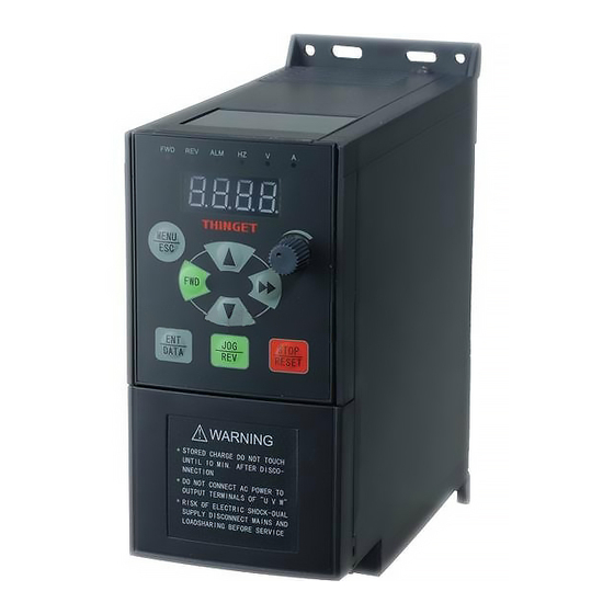
- Page 16 VB3/V5/VB5 series inverter 4 bits LED display MENU DATA Buttons STOP RESET Control terminals Analog potentiometer Power terminals Mounting hole series series 1.5KW~3.7KW 1.5KW~3.7KW series series 5.5KW~7.5KW 5.5KW~7.5KW VB5 series series 1.5KW~3.7KW 1.5KW~3.7KW VB5 series series 5.5KW~7.5KW 5.5KW~7.5KW...
- Page 17 VB3/V5/VB5 series inverter MENU MENU STOP DATA RESET STOP DATA RESET ! WARNING * STORED CHARGE DO NOT TOUCH UNTIL 10 MIN. AFTER DISCO- NNECTION * DO NOT CONNECT AC POWER TO OUTPUT TERMINALS OF "U V W" * RISK OF ELECTRIC SHOCK-DUAL SUPPLY DISCONNECT MAINS AND LOADSHARING BEFORE SERVICE series...
- Page 18 VB3/V5/VB5 series inverter 1-4. 1-4. 1-4. 1-4. Product Product Product Product d d d d imension imension imension imension series 0. 0. 0. 0.4 4 4 4 ~0.75 (Unit: � � � � V V V V B3 series 0.75 Unit: B3 series series...
- Page 19 VB3/V5/VB5 series inverter (Unit: � � � � VB5 series series series series 5.5~7.5KW 5.5~7.5KW 5.5~7.5KW 5.5~7.5KW Unit: Unit: Unit: mm mm) MENU STOP DATA RESET 167.0 180.0 � � � � (Unit: series series series 11 11 11 11~55 55 55 55KW Unit: Unit: V5 series...
- Page 20 VB3/V5/VB5 series inverter Type V5-4011 V5-4015 V5-4018 V5-4022 V5-4030 V5-4037 V5-4045 V5-4055 1-5. 1-5. 1-5. 1-5. Choose Choose Choose Choose f f f f ittings ittings ittings ittings � Brak Brak Resistor Resistor Brak Braking ing Resistor Resistor 1.5~18.5KW series inverters have braking unit inside (not include VB5-21P5). If you have the requirements of power consumption braking, choose braking resistor /unit according to table 1-1, 22KW and above inverters need to connect braking unit.
- Page 21 VB3/V5/VB5 series inverter 18.5 5000 27.2 5000 6000 BRU-4045 9600 13.6 9600 12000 � � � � O O O O per panel panel mounting mounting seat seat perate ate panel panel mounting mounting seat seat O O O O perate perate panel P P P P ower...
- Page 22 VB3/V5/VB5 series inverter 2 2 2 2 Installation Installation Installation and W W W W iring iring iring Installation and iring 2-1. Installation environment 2-1. 2-1. 2-1. Installation Installation Installation environment environment environment 2-1-1 2-1-1 2-1-1 2-1-1..Environment Environment Environment Environment r r r r equirement...
- Page 23 VB3/V5/VB5 series inverter 2-2. 2-2. Wiring Wiring 2-2. 2-2. Wiring Wiring Caution Caution Caution Caution � Wiring after power off for at least 10 minutes, otherwise, an electronic short may occur. � Do not connect AC power to output terminals U, V and W. �...
- Page 24 VB3/V5/VB5 series inverter Fig. A Fig. B Fig. C Fig. D Fig. E Fig. F Fig. G The relationship between main circuit terminals and inverter types: Main circuit I/O terminals are shown in table 2-1: Voltage level Power (KW) Figure Type 0.4~0.75 Fig.
- Page 25 VB3/V5/VB5 series inverter 2-4. 2-4. 2-4. 2-4. Basic Basic Basic Basic r r r r un unning ning ning ning w w w w iring iring iring iring Note Note Note: : : : Note (1) P- terminal is only used in 5.5KW and larger inverters. (2) L, N terminals are suitable for 220V single phase inverters.
- Page 26 VB3/V5/VB5 series inverter Fig 2 2 2 2 -4 4 4 4 (b b b b )control control control control panel panel panel panel jumper jumper jumper jumper position position position position 1.5~3.7KW VB5 series three phase inverter jumper position Fig 2 2 2 2 -4 4 4 4 (c c c c )control control panel...
- Page 27 VB3/V5/VB5 series inverter 1 - 2 connect : 4~20mA , AO Analog output terminal outputs current signal 0~10V terminal AO output 2-3 connect:0~10V,AO terminal outputs voltage signal 1-2 connect :V side:0~10V voltage CI current/voltage signal 4~20mA 2 - 3 connect : I side :...
- Page 28 VB3/V5/VB5 series inverter 3. CN2 terminals’ function description are shown as below: Table terminals terminals’ ’ ’ ’ function function description Table Table Table 2-4 2-4 CN2 CN2 terminals terminals function function description description description Type Terminal Name Terminal Function Description Specification Positive terminal...
-
Page 29: Wiring Diagram
VB3/V5/VB5 series inverter +10V power Offer +10V power supply Max output current:50mA supply (negative terminal:GND) +10V power supply Reference ground of analog signal common and +10V power supply COM is isolated with GND inside terminal inverter +24V power supply common Digital signal I/O common terminal terminal Shield... - Page 30 VB3/V5/VB5 series inverter F F F F ig. ig. ig. ig. 2-8 2-8 Analog Analog Analog Analog output output output output wiring wiring wiring wiring Note Note Note: : : : Note (1) When using analog input, you can connect filter capacitor or common mode inductor between VI and GND, or CI and GND.
-
Page 31: Control The Noise
VB3/V5/VB5 series inverter (Inverters (Inverters motors motors all all all grounded grounded grounded well well well) ) ) ) (Inverters (Inverters and and motors motors are are all grounded well Fig. 2-11 Connection Connection of of of of several several inverters Fig. - Page 32 VB3/V5/VB5 series inverter Table solution control noise Table Table Table 2-5 2-5 solution solution solution for for control control control noise noise noise Noise transmit Solution path When the external equipment forms a loop with the inverter, the equipment may operate incorrectly caused by leakage current of inverter grounding cable.
- Page 33 VB3/V5/VB5 series inverter (7) Do not connect other devices to inverter’s power input terminals (R, S, T or L,N ).
-
Page 34: Running State
V5 series inverter 3 3 3 3 Operating Operating Operating Instructions Instructions Operating Instructions Instructions 3-1. 3-1. inverter inverter 3-1. 3-1. Run Run the the inverter inverter 3-1-1. 3-1-1. Command Command channel channel inverter inverter running running 3-1-1. 3-1-1. Command Command channel channel for for inverter... - Page 35 V5 series inverter When the inverter is in the stopping state, it will running according to jog frequency (refer to P3.06~P3.08 for details) after receiving jog running command (e.g after pressing key) 1 1 1 1 :Close Close Close Close loop loop loop loop...
-
Page 36: Keyboard Function
V5 series inverter panel and control terminals, operation panel is shown in Fig.3-2. VB3 0.4~0.75KW 0.4~0.75KW 0.4~0.75KW 0.4~0.75KW VB5-OPU-01 VB5-OPU-01 VB5-OPU-01 VB5-OPU-01 V5-OPU-03 V5-OPU-03 V5-OPU-03 V5-OPU-03 MENU MENU DATA STOP RESET MENU ENTER DATA STOP DATA RESET STOP RESET Fig. Fig. - Page 37 V5 series inverter 3-2-3. 3-2-3. Fucntion Fucntion description description description of of of of LED indicator indicator 3-2-3. 3-2-3. Fucntion Fucntion description LED and and indicator indicator The operation panel consists of 4 bits-8 segments LED, 3 unit indicators and 3 state indicators. The three unit indicators have 6 different combinations and each combination corresponds to one type of unit while settting parameters.The relationship between the combination of the indicators and the unit are shown in Fig.3-3.
- Page 38 V5 series inverter Power on and Stop status, display running status, Fig. A Fig. B Fig. C initialize, display the stop parameters display the running the dynamic picture parameters Fig. 3 3 3 3 -4 4 4 4 Display Fig. Display during initialize,...
- Page 39 V5 series inverter Fig. 3 3 3 3 -6 6 6 6 Editing Fig. Fig. Editing Editing status status Fig. Editing status status 3- 3- 3- 3-2-5 2-5..Panel Panel Panel Panel operation operation operation operation procedure procedure procedure procedure...
- Page 40 V5 series inverter F F F F ig. ig. ig. ig. 3-8 Parameter Parameter editing editing 3-8 Parameter Parameter editing editing In the third level menu, the parameter can’t be changed if none digit of the parameter is flashing, the possible reasons are: (1) The setting of this parameter can not be changed, such as the actural detected parameters or recorded parameters.
- Page 41 V5 series inverter 5 5 5 5 ..Inquiry Inquiry fault parameters: Inquiry Inquiry fault fault fault parameters: parameters: parameters: Fig. Fig. 3-11 3-11 Inquiry Inquiry operation operation operation in in in in fault fault fault status status Fig.
- Page 42 V5 series inverter Fig. 3-12 Procedures Procedures of of of of starting starting driver first time Fig. Fig. Fig. 3-12 3-12 3-12 Procedures Procedures starting starting the the driver driver driver for for the the first first first time time time...
- Page 43 V5 series inverter 4 4 4 4 Function Function Function Parameters Parameters Function Parameters Parameters 4-1. 4-1. Function Function parameter parameter table table 4-1. 4-1. Function Function parameter parameter table table “ ○ ” : Parameters can be changed while running “...
- Page 44 V5 series inverter lection 1:S curve Acc/Dec ○ P0.14 Low speed time of S 10.0%~50.0%(Acc/Dec time) 0.1% 20.0% ramp P0.14+P0.15<90% ○ P0.15 Linear time of S 10.0%~80.0%(Acc/Dec time) 0.1% 60.0% ramp P0.14+P0.15<90% × P0.16 Acc/Dec time unit 0:second 1:minute ○ P0.17 Acc time 1 0.1~6000.0...
- Page 45 V5 series inverter ○ P1.07 Min reference of CI 0.00~ P1.09 0.01V 0.00V ○ P1.08 Frequency 0.00~high frequency limit 0.01Hz 0.00Hz corresponding min reference of CI P1.07 ~10.00V ○ P1.09 Max reference of 0.01V 10.00V ○ P1.10 Frequency 0.00~high frequency limit 0.01Hz 50.00Hz corresponding...
- Page 46 V5 series inverter frequency at stop ○ P2.07 injection braking 0.0~60.0s 0.1s 0.0s waiting time at stop ○ P2.08 injection braking 0.0~80.0% 0.1% 0.0% current at stop 4 4 4 4 ..Auxiliary Auxiliary running parameters parameters ( ( ( ( G G G G roup roup P3) ) ) ) Auxiliary...
- Page 47 V5 series inverter × P3.01 Parameter initialization Unit’s place: locking up 0: All parameters are allowed modifying 1: Only P3.01 can be modified 2:Only P0.02 and P3.01 can be modified Ten’s place: 0:disabled 1:Restore to factory setting 2:Clear fault record ×...
- Page 48 V5 series inverter ontrol PLC 0.0:Detection disabled × P3.12 Delay for responding to 0~1000ms control PLC × P3.13 Reference proportion of 0.01~1.00 0.01 1.00 communication frequency ○ P3.14 Acc time 2 0.1~6000.0 10.0 ○ P3.15 Dec time 2 0.1~6000.0 10.0 ○...
- Page 49 V5 series inverter ion 2 Unit’s place:b-25~b-28 Ten’s place:b-29~b-32 Hundred’s place:b-33~b-36 Thousand’s place:b-37~b-40 ○ P3.43 Display parameters 0000~4040 0001 Ten’s place, unit’s pladce :stop selection 3 displayed parameter selection Thousand’s place, hundred’s place : run displayed parameter selection ○ P3.44 Display 0.1~60.0 coefficient without unit...
- Page 50 V5 series inverter 19:Frequency selector 1 20:Frequency selector 2 21:Frequency selector 3 22:Terminal control mode is forcibly enabled 23:Control mode selector 1 24:Control mode selector 2 25:Start traverse operation 26 : Reset the traverse operation status 27:Close-loop disabled 28 : Pause the PLC operation 29:PLC disabled...
- Page 51 V5 series inverter 2 : Frequency detection threshold(FDT1) 3 : Frequency detection threshold(FDT2) : Overload pre- alarm(OL) 5 : Inverter under voltage locking(LU) : External fault stop(EXT) 7: Output frequency arrive upper limit of(FH) 8:Output frequency arrive lower limit(FL) 9 : Inverter zero speed running 10 :...
- Page 52 V5 series inverter nverter’s rated voltage) 3:Bus voltage(0~800V) 4:PID reference 5:PID feedback 6:VI(0~10V) 7:CI(0~10V/4~20mA) Analog output ( AO)gain ○ P4.18 0.50~2.00 0.01 1.00 setup ○ P4.19 AO output mode 0:4~20mA 1:0~10V ○ P4.20 DO output terminal 0:Output frequency(0~ upper limit frequency)...
- Page 53 V5 series inverter ○ P5.05 Frequeny decrease rate 0.00~99.99Hz/s 0.01Hz/s 10.00Hz/s when current limiting × P5.06 Auto current limiting 0:Disabled in constant speed selection 1: Enabled in constant speed Note:Enabled at Acc/Dec × P5.07 setting of the restart after 0:Disabled power off 1:Enabled ×...
- Page 54 V5 series inverter 2: Analog reference by CI ○ P7.02 Feedback channel selection 0:VI (0~10V) 1: Analog reference by CI 2:VI+CI 3:VI-CI 4:Min{VI,CI} 5:Max{VI,CI} ○ P7.03 Reference filter 0.01~50.00s 0.01s 0.50s ○ P7.04 Feedback filter 0.01~50.00s 0.01s 0.50s ○ P7.05 Set reference in digital mode 0.00~10.00V 0.01V...
- Page 55 V5 series inverter 0:Run again from stage 1 1: Continue to run from the stopping stage Hundred’s place: Save at power off 0:Not saving 1: Save the time and frequency at power off Thousand’s place :Selecting the unit of time 0:second 1:minute ○...
- Page 56 V5 series inverter 1:Manual mode Ten’s place of LED:Amplitude control 0:Variable amplitude 1:Fixed amplitude ○ P9.02 Pre-traverse frequecncy 0.00~500.00Hz 0.01Hz 0.00Hz Waiting time before pre- ○ P9.03 0.0~3600.0s 0.1s 0.0s traverse frequency ○ P9.04 Traverse operating amplitude 0.0~50.0% 0.1% 0.0% ○...
- Page 57 V5 series inverter × PA.09 Stator resistance of motor 0.001~50.000Ω 0.001Ω Dependent inverter’s model × PA.10 Rotor resistance of motor 0.001~50.000Ω 0.001Ω Dependent inverter’s model × PA.11 Over current protection 0~15 coefficient of torque × PA.12 Percentage adjustment 50~120 coefficient of speed deviation ×...
- Page 58 V5 series inverter PF.02 Software version PF.03~PF.10 Reversed 14 14 14 14..B B B B —Monitor Monitor Monitor function function parameters parameters Monitor function function parameters parameters B B B B —Monitor Monitor Monitor Monitor function function function function parameters...
- Page 59 V5 series inverter...
- Page 60 V5 series inverter 4-2. 4-2. 4-2. 4-2. Parameter Parameter Parameter Parameter d d d d escription escription escription escription 4-2-1 4-2-1 4-2-1 4-2-1..Basic Basic Basic Basic operating operating operating operating function function function function parameters parameters parameters parameters(Group Group...
- Page 61 V5 series inverter P0.04 running direction 00 00 00 00 P0.04 P0.04 P0.04 Set running running running direction direction direction Range Range Range Range:00 00 00 00~11 11 11 11 The unit’s place of this parameter is active with panel control mode to operate jog. Unit’s place of LED:...
- Page 62 V5 series inverter (a)Torque boost of constant torque curve (b)Torque boost of square torque curve Fig. 4 4 4 4 —3 3 3 3 Torque Fig. Fig. Torque Torque boost boost Fig. Torque boost boost P0.10 Cut-off frequency frequency of of of of torque torque boost Range...
- Page 63 V5 series inverter Note Note Note:(1) In order to achieve better performances, the ratio of carrierfrequency to the maximum running frequency of the Note inverter should be less than 36. (2) When the carrier frequency is low, the current display value may has error. Range:0 0 0 0 、1 1 1 1 P0.13 Acc/Dec...
- Page 64 V5 series inverter Fig. Fig. Acc/Dec Acc/Dec time time Fig. Fig.4-6 4-6 Acc/Dec Acc/Dec time time Note Note Note:(1)This series inverter defines seven kinds of Acc/Dec time. Here only defines Acc/Dec time 1, Acc/Dec time 2~7 are Note defined in P3.14~P3.25. (2)Minute and second as the time unit of Acc/Dec time 1~7 can be selected via P0.09 and the default unit is second.
- Page 65 V5 series inverter Fig. Fig. Fig. Fig.4 4 4 4 - - - - 7 7 7 7 V/F V/F curve curve curve curve Fig. Fig. Fig. Fig. 4 4 4 4 - - - - 8 8 8 8 U U U U ser-defined ser-defined ser-defined ser-defined V/F...
- Page 66 V5 series inverter P1.11 input pulse frequency frequency of of of of PULSE PULSE 10.0K P1.11 P1.11 P1.11 Max input input input pulse pulse pulse frequency frequency PULSE PULSE Range Range Range Range:0.1 0.1~20.0K 20.0K 20.0K 20.0K 10.0K 10.0K 10.0K P1.12 P1.12 P1.12...
- Page 67 V5 series inverter 4-2-3 4-2-3 4-2-3..Starting Starting Starting braking braking parameters parameters Group Group 4-2-3 Starting and and braking braking parameters parameters(Group Group P2 P2) P2.00 P2.00 Starting Starting mode mode Range Range:0 0 0 0 , , , , 1 1 1 1 , , , , 2 2 2 2 0 0 0 0 P2.00 P2.00...
- Page 68 V5 series inverter DC injection braking current at start is a percentage value of inverter’s rated current. There is no DC injection braking when the braking time is 0.00s. Fig. Fig. Fig. Fig.4-11 4-11 4-11 4-11 Starting Starting Starting Starting mode mode mode mode 1 1 1 1...
- Page 69 V5 series inverter 9:RS485-CI-Increase/Decrease key reference 10:RS485+CI+External pulse reference 11:RS485-CI-External pulse reference 12:RS485+VI+External pulse reference 13:RS485-VI-External pulse reference 14:VI+CI+Increase/Decrease key reference+Digital setting P0.02 15:VI+CI-Increase/Decrease key reference+Digital setting P0.02 16:MAX(VI,CI) 17:MIN(VI,CI) 18:MAX(VI,CI,PLUSE) 19:MIN(VI,CI,PLUSE) 20:VI,CI is active,VI is priority Parameter Parameter initialization initialization Parameter Parameter initialization...
- Page 70 V5 series inverter speed at a certain value with dynamic compensation for slip frequency of asynchronism motor. If use auto-torque boost function in addition, better low speed moment characteristic can be get. As shown in Fig.4-13. Fig. Fig. 4-13 4-13 Slip Slip Compensation...
- Page 71 V5 series inverter 5:38400BPS Ten’ ’ ’ ’ s s s s place place place place of of of of LED LED: Set digital format, the values are show below: 0:1-7-2 format,no parity check;1 stop bit ,7 data bits,2 stop bits,no parity check. 1:1-7-1 format,odd;1 stop bit,7 data bits,1 stop bits,odd 2:1-7-1 format,even;1 stop bit,7 data bits,1 stop bit,even 3:1-8-2 format,no parity check;1 stop bit,8 data bits,2 stop bits,no parity check.
- Page 72 V5 series inverter P3.26 Multi-frequency Multi-frequency 1 1 1 1 5.00H 5.00Hz z z z P3.26 P3.26 P3.26 Multi-frequency Multi-frequency Range Range Range Range:lower lower lower lower limit limit limit limit of of of of frequency frequency frequency frequency~upper upper upper upper limit limit...
- Page 73 V5 series inverter C: C: C: Ten Ten’ ’ ’ ’ s s s s place, place, place, D: D: D: Unit Unit Unit Unit’ ’ ’ ’ s s s s place place place place, D: place Display Display Display Display parameters parameters...
- Page 74 V5 series inverter Control terminal leave unused Frequency selector 1 Multi-step speed control terminal 1 Frequency selector 2 Multi-step speed control terminal 2 Frequency selector 3 Multi-step speed control terminal 3 Terminal control mode is forcibly enabled Exteral terminal for forward jog operation Control mode selector 1 Exteral terminal for reverse jog operation Control mode selector 2...
- Page 75 V5 series inverter The definition of X1, X2 and X3 are shown below: P4.00=1, P4.01=2, P4.03=3,X1, X2 and X3 can be used to achieve multi-step speed operation, as shown in Fig.4-18. Fig. Fig. Fig. Fig.4-18 4-18 4-18 4-18 Multi-step Multi-step Multi-step Multi-step speed speed...
- Page 76 V5 series inverter 12 12 12 12: : : : DC DC injection injection injection injection braking braking braking braking command command command command DB DB, , , , the terminal can be used to perform DC injection braking to the motor that is running so as to realize the emergent stop and accurate location of the motor.
- Page 77 V5 series inverter and the setting of start/stop control, direction, Acc/Dec time mode in low level operation. Note Note Note:Switching between close-loop operation and low level operation can be realized only when close-loop is enabled Note (P7.00 =1). 28 28 28 28:Pause Pause Pause operation...
- Page 78 V5 series inverter Fig. Fig. Fig. Fig. 4-23 4-23 4-23 4-23 3-wire 3-wire 3-wire 3-wire operation operation operation operation mode mode mode mode 1 1 1 1 Xi is the multi-function input terminal of X1~X6, here you should define its function as No.9 “3-wire control mode”. 3 3 3 3 :3-wire 3-wire control...
- Page 79 V5 series inverter Stop braking time Output frequency arrive upper limit(FH) High and lower limits of traverse operating frequency Output frequency arrive lower limit(FL) Inverter zero speed running set running time arriving Simple PLC Pause running finished Instruction Instruction Instruction Instructions s s s of of of of the the functions functions...
- Page 80 V5 series inverter 20 20 20 20:Set running time arriving..When the accumulating time(P3.40)arrive the reference time (P3.39), an indication signal will be output. P4.12 P4.12 P4.12 P4.12 Detecting Detecting Detecting Detecting range range range range of of of of frequency frequency frequency frequency arrive...
- Page 81 V5 series inverter 0~10V/4~20mA As to the analog output of AO, you can adjust the output gain to change the measuring range or calibrate the meter. Range:0 0 0 0 、1 1 1 1 P4.19 P4.19 P4.19 P4.19 AO output output output output mode...
- Page 82 V5 series inverter 4-2-6 4-2-6 4-2-6..Protective Protective Protective function function parameters parameters Group Group 4-2-6 Protective function function parameters parameters(Group Group P5 P5) P5.00 P5.00 Motor Motor overload overload protection protection mode mode selection selection Range Range:0 0 0 0 , , , , 1 1 1 1 0 0 0 0 P5.00...
- Page 83 V5 series inverter Fig. Fig. 4-31 4-31 Over Over voltage voltage function function Fig. Fig. 4-31 4-31 Over Over voltage voltage function function P5.04 P5.04 P5.04 P5.04 Auto current limiting threshold Range Range 200( 200( 200(%) ) ) ) 150(%) 150(%) 150(%) 150(%)
- Page 84 V5 series inverter (2) This function is disabled with the fault protection caused by overload and overheat. 4-2-7 4-2-7 4-2-7 4-2-7..Fault Fault Fault Fault recording recording recording recording parameters parameters parameters parameters(Group Group Group Group P6 P6)...
- Page 85 V5 series inverter adjustment are defined in P7.01~P7.11. The relationship between reference and feedback are shown in Fig4-34, thereinto, 10V corresponds to 100% of reference and 20mA corresponds to 100% of feedback. The aim of reference adjustment and feedback adjustment is to confirm the corresponding relationship and dimension of unification, as shown in Fig.4-33.
- Page 86 V5 series inverter Both the external reference signal and feedback signal have interferences, while these can be filtered by setting the time constant of filter (P7.03 and P7.04), the longer the filter time, the better the immunity capability, but the slower the response; on the contrary, the shorter the filter time , the worse the immunity capability, but the quicker the response.
- Page 87 V5 series inverter Fig. Fig. 4-37 4-37 Limits Limits Limits of of of of deviation deviation deviation Fig. Fig. 4-38 4-38 close-loop close-loop preset preset frequency frequency Fig. Fig.4-37 4-37 Limits deviation Fig. Fig.4-38 4-38 close-loop close-loop preset preset frequency frequency P7.14 P7.14...
- Page 88 V5 series inverter After start command is set out, the motor will start and accelerate to the frequency in the Acc time until the setting frequency reach or exceeds the certain value Fb. Stop process: The inverter will not stop immediatelyif the setting frequency is lower than Fb, only when the setting frequency reach Fa, the inverter will stop output.
- Page 89 V5 series inverter command is input. Fig. Fig. 4-42 4-42 holding holding mode mode after after single single cycle cycle Fig. Fig. 4-42 4-42 PLC PLC holding holding mode mode after after single single cycle cycle Fig. Fig. 4-43 4-43 operate operate conti...
- Page 90 V5 series inverter Fig. Fig. Fig. Fig.4-44 4-44 4-44 4-44 PLC PLC start start start start mode mode mode mode 1 1 1 1 Ten’ ’ ’ ’ s s s s place place place place of of of of LED LED:Save at power off 0 0 0 0 :Not Not saving.
- Page 91 V5 series inverter 0 0 0 0 :Run Run forward forward forward forward 1 1 1 1 :Run reverse reverse Run reverse reverse 2 2 2 2 :Decided Decided Decided Decided by by by by operating operating operating operating instructions instructions instructions instructions...
- Page 92 V5 series inverter P9.00 P9.00 P9.00 P9.00 Traverse Traverse Traverse Traverse operation operation operation operation selection selection selection selection Range Range Range:0 0 0 0 , , , , 1 1 1 1 0 0 0 0 Range 0 0 0 0 :Disabled Disabled Disabled Disabled...
- Page 93 V5 series inverter The calculated length can be corrected through times of length (P9.10) and correction coefficient of length (P9.11), and the corrected length is the actual length. Actual length =calculated length×correction coefficient of length÷correcting coefficient of length When actual length(P9.09)≥preset length(P9.08), the inverter will send out a STOP command to stop.When the inverter restarts, it needs to clear the actual length (P9.09) or modify actual length (P9.09)<...
- Page 94 V5 series inverter iation iation iation iation Integral adjustment coefficient coefficient of of of of speed speed Integral Integral Integral adjustment adjustment adjustment coefficient coefficient speed speed PA.13 PA.13 PA.13 PA.13 Range Range Range Range:100 100~500 deviation deviation deviation deviation In vector control, PA.12~PA.13 are used for control motor speed.Adjust the two parameters can realize better effect for motor speed control.
- Page 95 V5 series inverter PF.01 User User’ ’ ’ ’ s s s s password password 0000 PF.01 PF.01 PF.01 User User password password Range Range Range Range:0000 0000 0000 0000~9999 9999 9999 9999 0000 0000 0000 This parameter can be protect against unauthorized personnel to view or modify function parameters. If user’s password don’t need, you can set 0000 as its value.
- Page 96 V5 series inverter 5 5 5 5 Fault Fault Fault Diagnosis Diagnosis Countermeasures Countermeasures Fault Diagnosis Diagnosis and and Countermeasures Countermeasures 5-1. 5-1. Fault Fault diagnosis diagnosis countermeasurs countermeasurs 5-1. 5-1. Fault Fault diagnosis diagnosis and and countermeasurs countermeasurs When fault occurs, the function code and its contents will be shown in LED display, the protection function starts, the inverter stops outputting and the fault relay contact point is activated.Before seeking services, the subscriber may conduct the self- check according to the prompt given in this section, analyze the fault causes, and find out the solutions.If the fault belongs to the causes described in the broken line box, please seek the service by contacting the inverter agent or directly contacting our...
- Page 97 V5 series inverter Reduce DC injection braking current and prolong braking DC injection braking current is too big time V/F curve is not suitable Adjust V/F curve and torque boost value The rotating motor restarts after stop Set “start of fly” function Low AC supply voltage Check AC supply voltage Too heavy load...
- Page 98 V5 series inverter PROM Press key to reset or seek service E-17 W/R error of control parameter W/R error E-18 Decrease the brake current % DC brake overcurrent Set wrong current of DC brake Main circuit lack Lack of phase when input current, momentary Check the reason and reset voltage,the power off, power supply point loose, power...
-
Page 99: Routine Maintenance
V5 series inverter 6 6 6 6 Maint Maint Maint Mainte e e e n n n n an an an ance ce ce ce 6-1. 6-1. Maintenance Maintenance 6-1. 6-1. Maintenance Maintenance Environment effections such as ambient temperature, humidity, fog ,internal component aging and other factors will give rise to the occurrence of potential faults. - Page 100 Xinje electronic Co.,Ltd will offer warranty service in the case of the following situations: (1) The warranty clause is only confined to the inverter; (2) We will take the responsibility of 15 months defects liability period for any faults or damages under the normal operation conditions.
-
Page 101: Communicating Mode
V5 series inverter 7 7 7 7 Communication Communication Communication Communication P P P P rotocol rotocol rotocol rotocol 7-1. 7-1. 7-1. 7-1. O O O O verview verview verview verview of of of of communication communication communication communication protocol protocol protocol protocol... -
Page 102: Structure
V5 series inverter (2) The inverter is a master in the network, the slave will not response to the command sent by the inverter via broadcast address. (3) Users can set the inverter’s current address, baud rate and data format by using the inverter’s keypad or through the serialcommunication port. - Page 103 V5 series inverter 2 2 2 2 ..Communication Communication Communication Communication address address address address: 00H:broadcast for all the inverters(broadcast) 01H:communicate with the inverter addressed 01 0FH:communicate with the inverter addressed 15 10H:communicate with the inverter addressed 16 By parity of reasoning……….,max can reach 254(FEH)...
-
Page 104: Communication Parameter
V5 series inverter Data Data CRC CHECK Low CRC CHECK Low CRC CHECK High CRC CHECK High (4) function code 10H: write several data in the register Note: V5/VB5 inverters only support one pack of data write. For example: write P0.06=50.00Hz in inverter address 01H. RTU mode: Inquiry information format Reply information format... - Page 105 V5 series inverter 2001H Set frequenc command via port 2100H Read inverter’s fault parameter Read inverter’s status BIT0:stop indicate,0:Stop;1:Run BIT1: ,1:low voltage;0:normal BIT2:forward/reverse indicate,1:forward;0:reverse BIT3:jog indicate 1:jog;0: none BIT4:close loop control selection,1:close loop;0: none Monitor inverter’s status BIT5:traverse mode running flag,1:traverse;0:none 2101H (03H)...
- Page 106 V5 series inverter 01H,06H,20H,00H,00H,01H,CRC1,CRC2 Definition Definition of of of of fault fault code Definition Definition fault fault code code code: Fault code Instruction Fault Fault Fault code code code Instruction Instruction Instruction Fault function code. Inverter can not find :03H,06H,08H。 Fault data address.
- Page 107 无锡市信捷科技电子有限公司 Xinje Xinje Electronic Electronic Co., Co., Ltd. Ltd. Xinje Xinje Electronic Electronic Co., Co., Ltd. Ltd. 江苏省无锡市蠡园开发区 4th Floor Building 7,Orignality Industry park, 创意产业园 7 号楼四楼 Liyuan Development Zone, Wuxi City, 邮编: 214072 Jiangsu Province, China 214072 电话: 86-510-85134136 Tel: 86-510-85134136 传真:...
Need help?
Do you have a question about the VB3-20P7 and is the answer not in the manual?
Questions and answers