Table of Contents
Advertisement
Advertisement
Table of Contents

Subscribe to Our Youtube Channel
Related Manuals for Stryker 1588-010-000


Summary of Contents for Stryker 1588-010-000
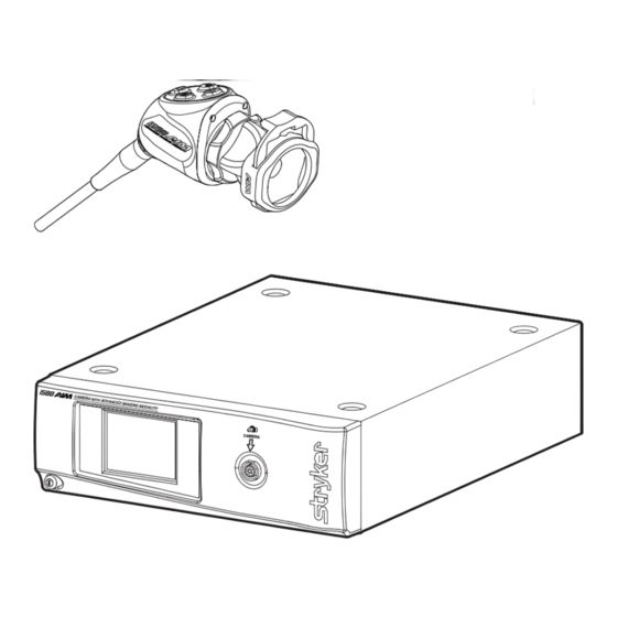
- Page 1 1588 AIM Video Camera 1588-010-000 1588-210-105 1588-610-122 1588-710-105...
-
Page 3: Table Of Contents
Contents Warnings and Cautions ................1 Cautions ........................1 Warnings: General ....................2 Warnings: ENV Mode ....................3 Operating the Camera with a Light Source ............4 Product Description and Intended Use ..........5 Indications ........................6 The Camera Console ....................7 The Camera Head ....................9 The C-Mount Coupler .................. - Page 4 Periodic Maintenance Schedule ..............46 Expected Service Life ..................46 Disposal and Recycling Information .............. 46 Recycling Diagrams ..................... 47 Technical Specifications ................ 49 Electromagnetic Compatibility ................ 51 Symbol Definitions ................55...
-
Page 5: Warnings And Cautions
Always treat the camera system with care. The camera system contains sensitive parts that are precisely aligned and may suffer damage if dropped or mistreated. Ensure that readjustments, modifications, and/or repairs are carried out by persons authorized by Stryker Endoscopy. -
Page 6: Warnings: General
Warnings: General To avoid potential serious injury to the user and the patient and/or damage to this device, please note the following general warnings. Must be a qualified physician to use this equipment. Read this operating manual thoroughly, especially the warnings, and be familiar with its contents before connecting and using this device. -
Page 7: Warnings: Env Mode
Warnings: ENV Mode IMPORTANT SAFETY NOTICE - LASER RADIATION: Endoscopic Near-Infrared Visualization (ENV) mode controls a Class 1M laser emitted from the L10 LED Light Source with AIM Technology (0220-220-300). Use of controls or performance of procedures other than those specified herein can result in hazardous laser radiation exposure and can cause severe eye injury to the patient or user. -
Page 8: Operating The Camera With A Light Source
Operating the Camera with a Light Source Please note the following warnings to avoid user or patient injury or product damage when using the camera with a light source. IMPORTANT SAFETY NOTICE - HIGH TEMPERATURES: Before operating this device, please read this operating manual thoroughly and carefully. -
Page 9: Product Description And Intended Use
1588-020-122 AIM Coupler, 18 mm, C-Mount Complete instructions are available in Stryker user manual P29925 (English) or P29926 (multilingual). Not compatible with ENV mode when the camera is used with the L10 LED Light Source with AIM Technology. Complete instructions are available in Stryker user manual P30104. -
Page 10: Indications
• examination of the evacuated cardiac chamber during performance of valve replacement The users of the Stryker 1588 AIM Video Camera with Infrared Compatibility are general surgeons, gynecologists, cardiac surgeons, thoracic surgeons, plastic surgeons, orthopedic surgeons, ENT surgeons and urologists. -
Page 11: The Camera Console
The touchscreen also allows activation of remote outputs, which are commonly used with a Stryker digital capture console to record images and video. See the Operation section for more detail on using the front panel. - Page 12 Rear Panel The console rear panel provides ports for connecting the 1588 AIM Camera to viewing and recording equipment, such as video monitors and Stryker device control consoles. 1. Device Control Port Connects to a Stryker device control console (such as the SDC3 or SIDNE®) to enable voice operation and/or graphic tablet control 2.
-
Page 13: The Camera Head
The Camera Head The camera head connects to the camera console and produces video and photographic images, which it relays to the camera console. Several controls are accessible through a button keypad located on the top of the camera head (see the Operation section). 1. -
Page 14: The C-Mount Coupler
It is recommended to use the camera with the AIM Coupler (1588-020-122). The AIM Coupler enables use of ENV mode when the camera is connected to the L10 LED Light Source with AIM Technology. Refer to Stryker user manual P30104 for complete AIM Coupler instructions. -
Page 15: Setup And Interconnection
Setup and Interconnection Stryker Endoscopy considers instructional training, or inservice, an integral part of the 1588 AIM Camera. Your local Stryker Endoscopy sales representative will perform at least one inservice at your convenience to help set up your equipment and instruct you and your staff on its operation and maintenance. -
Page 16: Setting Up The Console
When using any device with unterminated analog video inputs, connect a cable from the VIDEO OUT of that device to the VIDEO IN on the monitor. Connect the DVI output from the Stryker digital capture console to the DVI input on the display monitor. -
Page 17: Wiring Diagram
Wiring Diagram VisionPro 26" LED Surgical Display (underside shown) SDC3 1588 AIM Camera L10 Light Source SDC/SIDNE... -
Page 18: Setting Up The Camera Head
Setting Up the Camera Head Do not severely bend the camera cable or damage may result. Unscrew the soaking cap from the cable connector on the camera head. Align the arrow on the cable connector with the arrow above the camera- connector port on the front console panel. -
Page 19: Setting Up The Coupler
• When using the 1588 AIM Camera Head with Integrated Coupler (1588-610-122), skip to step 2. • When using the 1588 Pendulum Camera Head with Integrated Coupler (1588-310-130), see Stryker user manual P29925 (English) or P29926 (multilingual). • When using a direct-coupled C-Mount endoscope (a scope that requires no coupler), thread the endoscope directly into the camera head until it forms a tight seal, and skip to step 3. - Page 20 Note: For a list of endoscopes that are compatible with ENV mode, see Stryker user manual P27006 (English) or P27009 (multilingual) for the L10 LED Light Source with AIM Technology. • Remove the coupler dust cap if it is present.
-
Page 21: Installing The Soaking Cap
Installing the Soaking Cap Before reprocessing the camera head, the soaking cap must be installed to avoid damaging the cable connector. Caution: Failure to properly tighten the soaking cap will corrode the connector pins and void the warranty. • To install the soaking cap, screw the cap onto the threads of the cable connector until it forms a tight seal. -
Page 22: Operation
Controlling Remote Video Accessories The 1588 AIM Camera can remotely control up to two functions of a video accessory, such as a Stryker digital capture console. Commonly this enables the user to capture images or start and stop video recording. Remote video accessories can be controlled with the camera head’s P button or the console touchscreen. -
Page 23: Using The Camera Head Buttons
• Press the P button for less than two seconds to select Remote 1. One beep will sound. When the camera is connected to a Stryker digital capture console, this will Capture a Photo. • Press the P button for more than two seconds to select Remote 2. Two beeps will sound. - Page 24 Up and Down Buttons The up and down buttons change functionality depending on the conditions: Conditions Functionality of Up/Down buttons • Default • Up and down buttons increase or decrease the Automatic-Shutter Light Level in eight steps. • ENV mode is enabled •...
- Page 25 DRE mode can be turned on via the touchscreen DRE menu When DRE Desat is on, an indicator or by programming DRE Toggle appears below the light bulb icon. to another camera head button. Contact a Stryker representative for assistance with button programming.
-
Page 26: Programming Camera Head Buttons
Programming Camera Head Buttons The camera head buttons can be customized differently for each surgical specialty. Contact a Stryker representative for assistance with button programming. The button configuration for the selected surgical speciality will appear on the display monitor when the camera head is connected to the console. The button configuration will disappear once the P button is pressed. - Page 27 Strobe mode is an optional mode that can be used only in the Arthroscopy surgical specialty when the camera is connected to a Stryker L10 light source. When Strobe mode is on, this icon appears in the top-left corner of the display...
-
Page 28: Using The Touchscreen Interface
Using the Touchscreen Interface The touchscreen interface on the console provides controls for adjusting or capturing the video image. The menus are described below. Home Screen The Home Screen is the default screen. It displays the current camera mode and it provides access to subsequent menus and common camera functions. Use the arrows to scroll through preset camera settings designed for Surgical Specialties. - Page 29 Menu Screen The Menu screen provides options for adjusting the camera picture. Press the plus or minus button next to the brightness icon in order to increase or decrease the Automatic-Shutter Light Level. ü The level is indicated by the filled bars under the icon and on the display monitor.
- Page 30 DRE Mode Screen Dynamic Range Enhancement (DRE) Mode screen allows the user to turn DRE functions on and off. This screen is accessible only when the ENT/Skull, Arthroscopy, Cystoscopy, or Laparoscopy surgical specialty is selected. Press the left button to turn on DRE mode. Press the button again to turn off DRE mode.
-
Page 31: Using The Camera In Env Mode
P27006 (English) or P27009 (multilingual). Failure to follow all warnings can result in severe eye injury to the patient or user. Note: For complete system requirements to use ENV mode, see Stryker user manual P27006 (English) or P27009 (multilingual) for the L10 LED Light Source with AIM Technology. - Page 32 ü When ENV mode is enabled, the touchscreen and the ENV button change to a green background. Note: When ENV mode is enabled, the White Balance function is disabled on the Home screen. The DRE button is also not available in ENV mode. Note: When ENV mode is enabled, the brightness controls are disabled on the Menu screen.
-
Page 33: Performing The White Balance Test
• Video image settings • Touchscreen language settings • Light source Run/Standby controls • Other system settings These advanced features require in-depth knowledge of the device and should be performed only by trained personnel. For access to advanced features, contact a Stryker representative. -
Page 34: Troubleshooting
Troubleshooting Problem Possible Solution E1 error code • Turn off the console, wait 3 seconds, and turn it back on. E2 error code • Turn off the console, wait 3 seconds, and turn it back on. E3 error code • Turn off the console, wait 3 seconds, and turn it back on. - Page 35 Problem Possible Solution White Balance quality • See the solution for Picture is too dark. is not good • See the solution for Picture is too bright. • Perform the White Balance test with the light source connected to the scope. Use metal- halide, xenon, or LED lighting (no fluorescent lighting).
- Page 36 Problem Possible Solution Variability in color • Perform the White Balance test. (See the reproduction between Performing the White Balance Test section.) different light sources • Check the settings on video peripherals. or peripherals • Ensure the light source has a proper infrared filter (check with manufacturer specifications).
- Page 37 Light Source with AIM Technology • Confirm white light is activated on the light source Note: If this Troubleshooting section does not resolve the problem, call Stryker Technical Support at 1-877-478-7953 (inside the U.S.) or refer to the standard warranty.
-
Page 38: Reprocessing
Reprocessing The camera console is not intended to come into contact with the patient. It may be cleaned, but not sterilized. The camera head and coupler may contact the patient and should both be cleaned and sterilized prior to every use. •... -
Page 39: Cleaning, Disinfecting, And Sterilizing The Camera Head
These reprocessing instructions are provided in accordance with ISO 17664, AAMI TIR12, AAMI TIR30, AAMI ST79, and AAMI ST81. The instructions have been validated by Stryker as being capable of preparing the device for re-use. To achieve the desired result, the processor shall ensure that the following instructions are performed as written in their entirety and as appropriate in the processor’s facility. -
Page 40: Materials And Equipment
• Inspect the camera cable for cuts and breaks before soaking in any fluid. Return any damaged camera to Stryker for service. • Never soak the camera in the same tray with sharp instruments. - Page 41 Cleaning Water basin Large enough to accommodate camera head without excessive bending of cable Enzymatic detergent Used in cleaning solution to remove surgical debris Tap water To prepare cleaning solutions Syringe To inject detergent into hard-to-reach areas of device Soft-bristle brush To clean exterior of device or hard-to-reach areas of device Reverse osmosis/...
- Page 42 Instructions for Reprocessing Point of Use • Disassemble the camera head from the scope and coupler. To disconnect the scope, depress the endobody clamp on the coupler and remove the scope from the coupler. To disconnect the coupler, grip the rear adapter of the coupler and unscrew it counterclockwise from the camera head.
- Page 43 2. Brush • Thoroughly brush the exterior of the device with a soft-bristle brush for 90 seconds, focusing on any mated or rough surfaces. • Use a syringe to inject 50 mL of the detergent into any crevices and mated surfaces 5 times. •...
- Page 44 6. Rinse • Remove the device from the prepared detergent. Rinse the device with reverse osmosis/deionized water at ambient temperature for 90 seconds or until all visible detergent residue is removed. • Flush any crevices and mated surfaces 5 times. After all visible detergent residue is removed, continue to rinse for 30 seconds.
- Page 45 3. Rinse • Remove the device from the prepared detergent. Rinse the device with reverse osmosis/deionized water at ambient temperature for 90 seconds or until all visible detergent residue is removed. • After all visible detergent residue is removed, continue to rinse for 30 seconds.
- Page 46 High-Level Disinfection (Optional) The device must be sterilized after disinfection. Failure to sterilize the device before reuse presents an acute infection control risk to the patient. Note: For necessary materials and equipment, see the Materials and Equipment table. The device can be disinfected using a disinfecting solution that has the following active ingredient: ≥...
- Page 47 Steris/Amsco V-PRO Clean and prepare the device as recommended in this user manual. Ensure the soaking cap is installed. If using a sterilization tray (optional), follow any additional instructions provided with the tray. Use only trays that are approved for sterilization with V-PRO. Double wrap the device (or tray) prior to sterilization.
- Page 48 Ethylene Oxide (EO) Clean and prepare the device as recommended in this user manual. Ensure the soaking cap is installed. If using a sterilization tray (optional), follow any additional instructions provided with the tray. Use only trays that are compatible with EO. Double wrap the device (or tray) prior to sterilization.
-
Page 49: User Maintenance
• Inspect all components for cleanliness. If fluid or tissue buildup is present, repeat the above cleaning and sterilization procedures. • Inspect the camera cable for cuts and breaks. Return any damaged camera to Stryker for service. Using Sterile Drapes Using sterile drapes will ensure maximum longevity of your 1588 AIM Camera. -
Page 50: Periodic Maintenance Schedule
Note: Refer calibration and operating difficulties not detailed in this manual to your Stryker Endoscopy sales representative. Expected Service Life The 1588 AIM Camera Control Unit has an expected service life of 1540 uses (four years based on approximately two uses per day). -
Page 51: Recycling Diagrams
Recycling Diagrams Console Item Material Qty. Comments Touchscreen LCD Not shown above; on front panel PC Board — PC Board — PC Board — Remote Cable Cable length abbreviated above AC Power Cord Cable length abbreviated above DVI Cable Cable length abbreviated above Power Supply —... - Page 52 Camera Head Camera head model 1588-210-105 is shown below. Item Material Qty. Comments Cable — Camera Head Enclosure The camera head enclosure that (PC Boards) contains PC Boards is sealed and cannot be dismantled without special equipment and training.
-
Page 53: Technical Specifications
Technical Specifications 60 Hz settings are displayed first. (50 Hz settings follow in parentheses.) Imaging System 1/3″ Progressive Scan CMOS High Definition Scanning System Horizontal: 64.00 kHz (60.00 kHz) Vertical: 60.02 Hz (50.00 Hz) Video Outputs Digital/Analog: Two Digital Video Interface (DVI)/RGBHV 1280 ×... - Page 54 Dimensions Camera Console: 12.5″ w × 4.0″ h × 15.25″ d (31.8 cm w × 10.2 cm h × 38.7 cm d) Camera Head Cable: 10 ft (3.05 m) sealed cable Classification Class I Equipment Continuous Operation Type BF Applied Part Ingress Protection, IPX0—Ordinary Equipment (1588 AIM console) Ingress Protection, IPX7—Protected against...
-
Page 55: Electromagnetic Compatibility
Electromagnetic Compatibility Like other electrical medical equipment, the 1588 AIM Camera requires special precautions to ensure electromagnetic compatibility with other electrical medical devices. To ensure electromagnetic compatibility (EMC), the camera system must be installed and operated according to the EMC information provided in this manual. Note: The 1588 AIM Camera has been designed and tested to comply with IEC 60601-1-2 requirements for EMC with other devices. - Page 56 Guidance and Manufacturer’s Declaration: Electromagnetic Immunity The 1588 AIM Camera is intended for use in the electromagnetic environment specified below. The customer or user of the camera system should ensure that it is used in such an environment. Immunity Test IEC 60601 Test Level Compliance Level Electromagnetic...
- Page 57 Guidance and Manufacturer’s Declaration: Electromagnetic Immunity The 1588 AIM Camera is intended for use in the electromagnetic environment specified below. The customer or user of the camera system should ensure that it is used in such an environment. Immunity Test IEC 60601 Test Level Compliance Electromagnetic Environment:...
- Page 58 Guidance and Manufacturer’s Declaration: Electromagnetic Immunity The 1588 AIM Camera is intended for use in the electromagnetic environment specified below. The customer or user of the camera system should ensure that it is used in such an environment. (a) Field strengths from fixed transmitters, such as base stations for radio (cellular/cordless) telephones and land mobile radios, amateur radio, AM and FM radio broadcast, and TV broadcast, cannot be predicted theoretically with accuracy.
-
Page 59: Symbol Definitions
Symbol Definitions This device and its labeling contain symbols that provide important information for the safe and proper use of the device. These symbols are defined below. Touchscreen Interface/Display Monitor White Balance button Capture photo Start/stop video recording Settings button (navigate to Menu screen) Brightness icon Zoom icon Home button (navigate to Home screen) - Page 60 Legal manufacturer Product catalog number Product serial number The device meets requirements for safety and effectiveness set forth in MDD 93/42/EEC. Stryker European representative Denotes compliance to CAN/CSA C22.2 No 60601-1 and ANSI/AAMI 60601-1 Type BF applied part 1588 AIM Camera Head connection...
- Page 61 Equipotentiality Alternating current Fuse rating Device recycling code (applicable in China) This product contains electrical waste or electronic equipment. It must not be disposed of as unsorted municipal waste and must be collected separately. User Manual A lightning bolt within a triangle is intended to warn of the presence of hazardous voltage.
- Page 64 Stryker Corporation or its divisions or other corporate affiliated entities own, use or have applied for the following trademarks or service marks: SIDNE, Ideal Eyes, Wingman, and the Stryker logo. All other trademarks are trademarks of their respective owners or holders. 2015/10...
Need help?
Do you have a question about the 1588-010-000 and is the answer not in the manual?
Questions and answers