Table of Contents
Advertisement
Advertisement
Table of Contents

Subscribe to Our Youtube Channel
Related Manuals for Stryker 0700010000


Summary of Contents for Stryker 0700010000
- Page 1 Precision AC Video Camera 0700010000 0700010001 0700410105...
-
Page 3: Table Of Contents
Contents Warnings and Cautions ................1 Product Description and Intended Use ..........4 Indications ........................5 Contraindications ....................5 The Camera Console ....................6 The Camera Head ....................8 The C-Mount Coupler .....................9 Setup and Interconnection ..............10 Setting Up the Console ..................11 Precision AC Wiring Diagram ................ - Page 4 Expected Service Life ..................40 Disposal and Recycling Information .............. 40 Diagrams ........................41 Technical Specifications ................ 43 Electromagnetic Compatibility ................ 45 Symbol Definitions ................49...
-
Page 5: Warnings And Cautions
Warnings and Cautions Please read this manual and follow its instructions carefully. The words warning, caution, and note carry special meaning and should be carefully reviewed: Warning Indicates risks to the safety of the patient or user. Failure to follow warnings may result in injury to the patient or user. Caution Indicates risks to the equipment. - Page 6 Warnings To avoid potential serious injury to the user and the patient and/or damage to this device, please note the following warnings: Must be a qualified physician to use this equipment. Carefully unpack this device and check if any damage occurred during shipment.
- Page 7 18. Attempt no internal repairs or adjustments not specifically detailed in this operating manual. 19. Ensure that readjustments, modifications, and/or repairs are carried out by persons authorized by Stryker Endoscopy. 20. The warranty is void if any of these warnings are disregarded.
-
Page 8: Product Description And Intended Use
The Precision AC console is also packaged with the following connection cables: • Remote cables, 2.5 mm to 3.5 mm (Qty: 2) • DVI-I cable (Qty: 1) • Hospital-grade power cord (Qty: 1) Contact your Stryker representative for availability of other cables that may be required for alternate configurations. -
Page 9: Indications
Indications The Precision AC Camera is indicated for use in general laparoscopy, nasopharyngoscopy, ear endoscopy, sinuscopy, and plastic surgery wherever a laparoscope/endoscope/arthroscope is indicated for use. A few examples of the more common endoscopic surgeries are listed below. • laparoscopic cholecystectomy • laparoscopic hernia repair •... -
Page 10: The Camera Console
The touchscreen also allows activation of remote outputs, which are commonly used with a Stryker digital capture console to record images and video. See the “Operation” section for more detail on using the front panel. - Page 11 Rear Panel The console rear panel provides ports for connecting the Precision AC Camera to viewing and recording equipment, such as video monitors and Stryker device control consoles. See the “Product Description” section for the different console models that are available. The Precision AC Camera Control Unit with DVI Fiber Output (0700010001) is shown below.
-
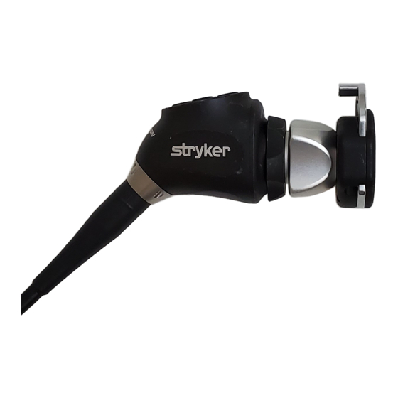
Page 12: The Camera Head
The Camera Head The camera head connects to the camera console and produces video and photographic images, which it relays to the camera console. Several controls are accessible through a button keypad located on the top of the camera head (see the “Operation” section). “AUTOCLAVE”... -
Page 13: The C-Mount Coupler
The coupler threads onto the face of the camera head, enabling a scope to be attached to the camera. It provides a focusing ring to adjust image sharpness. Refer to Stryker user guide P26183 for complete coupler instructions. 1. Rear Adapter Threads onto the camera head 2. -
Page 14: Setup And Interconnection
Setup and Interconnection Stryker Endoscopy considers instructional training, or inservice, an integral part of the Precision AC Camera. Your local Stryker Endoscopy sales representative will perform at least one inservice at your convenience to help set up your equipment and instruct you and your staff on its operation and maintenance. -
Page 15: Setting Up The Console
“Operation” section for details. Connect a USB A-to-B cable (also available from Stryker, part 0105187988) from the console’s Light Source output to the SIDNE input on the Stryker L9000 Light Source. • The Precision AC camera head can be programmed to toggle “Run/ Standby”... -
Page 16: Precision Ac Wiring Diagram
Precision AC Wiring Diagram VisionPro 26" LED Surgical Display (underside shown) SDC3 Precision AC Camera L9000 Light Source... -
Page 17: Setting Up The Camera Head
Setting Up the Camera Head Do not severely bend the camera cable or damage may result. Unscrew the soaking cap from the cable connector on the camera head. Align the arrow on the cable connector with the arrow above the camera- connector port on the front console panel. -
Page 18: Setting Up The Coupler
Setting Up the Coupler Steps 1–3 below provide instructions for connecting the camera head to the coupler. When using a direct-coupled C-Mount endoscope (a scope that requires no coupler), thread the endoscope directly into the camera head until it forms a tight seal, and skip to step 3. - Page 19 Attach an endoscope to the coupler. Note: For best results, use the Precision AC Camera with Stryker’s PEEK Precision Ideal Eyes™ HD scopes. Before each use, check the outer surface of the endoscope to ensure there are no rough surfaces, sharp edges, or protrusions.
-
Page 20: Connecting The Dvi Fiber Outputs
Connecting the DVI Fiber Outputs Using adjustments or performing procedures differently than specified below may result in hazardous radiation exposure. The Precision AC Camera has the optional upgrade, the fiber output, for model 0700010001. This upgrade contains four laser diodes to transmit a DVI output over fiberoptic cables. -
Page 21: Operation
Operation Note: Before operating the Precision AC Camera, ensure all system components have been set up according to the instructions in the “Setup and Interconnection” section. Operating the Camera with a Light Source IMPORTANT SAFETY NOTICE: Before operating this device, please read this operating manual thoroughly and carefully. When using this device with a light source, fire and/or severe injury may result to the patient, user or inanimate objects if the instructions in this manual are not followed. -
Page 22: Powering The Console On/Off
Controlling Remote Video Accessories The Precision AC Camera can remotely control up to two functions of a video accessory, such as a Stryker digital capture console. Commonly this enables the user to capture images or start and stop video recording. Remote video accessories can be controlled with the camera head’s P button or the console touchscreen. -
Page 23: Using The Camera Head Buttons
• Press the P button for less than two seconds to select Remote 1. One beep will sound. When the camera is connected to a Stryker digital capture console, this will capture a photo. • Press the P button for more than two seconds to select Remote 2. Two beeps will sound. -
Page 24: Using The Touchscreen Interface
Using the Touchscreen Interface The touchscreen interface on the console provides controls for adjusting or capturing the video image. The menus are described below. Home Screen The Home Screen is the default screen. It displays the current camera mode and it provides access to subsequent menus and common camera functions. Use the arrows to scroll through preset camera settings designed for surgical specialties. -
Page 25: Menu Screen
Menu Screen The Menu screen provides options for adjusting the camera picture. Press the plus or minus button below the Brightness icon in order to increase or decrease the automatic-shutter light level. ü The level is indicated by the green bars in the icon. Press the Light Bulb icon to activate Dynamic Range Enhancement (DRE). -
Page 26: Performing The White-Balance Test
• Button programming • Touchscreen language settings • Light source “Run/Standby” controls • Other system settings These advanced features require in-depth knowledge of the device and should be performed only by trained personnel. For access to advanced features, contact a Stryker representative. -
Page 27: Troubleshooting
Troubleshooting Problem Possible Solution E1 error code • Console shut down due to main board error. • Turn off the console, wait 3 seconds, and turn it back on. E2 error code • Console shut down due to digital board error. •... - Page 28 Problem Possible Solution No color bar (Optical • Same as “No color bar” above. DVI Fiber only) • See the “Connecting the DVI Fiber Outputs” section. Incorrect picture color • Perform the white-balance test. (See the “Performing the White-Balance Test” section.) •...
- Page 29 Problem Possible Solution No video picture when • Check to ensure that all devices in the video the camera head is system are plugged in and powered on. plugged in • Check the connector on the camera-head cable for broken pins. •...
- Page 30 SIDNE device does not • Contact your Stryker representative for recognize camera head compatibility settings. Note: If this troubleshooting guide does not resolve the problem, call Stryker Technical Support at 1-877-478-7953 (inside the U.S.) or refer to the standard warranty.
-
Page 31: Reprocessing
The camera head and coupler may contact the patient and should both be cleaned and sterilized prior to every use. Refer to the coupler user guide (Stryker part P26183) for instructions on reprocessing the coupler. -
Page 32: Cleaning, Disinfecting, And Sterilizing The Camera Head
These reprocessing instructions are provided in accordance with ISO 17664, ISO 17665, AAMI TIR12, AAMI ST79, and AAMI ST81. The instructions have been validated by Stryker as being capable of preparing the device for re-use. To achieve the desired result, the processor shall ensure that the following instructions are performed as written in their entirety and as appropriate in the processor’s facility. -
Page 33: Limitations On Reprocessing
• Inspect the camera cable for cuts and breaks before soaking in any fluid. Return any damaged camera to Stryker for service. • Never soak the camera in the same tray with sharp instruments. -
Page 34: Materials And Equipment
Materials and Equipment All materials and equipment required to reprocess the camera head shall be supplied by the user unless otherwise noted Item Description All phases Gloves, eye protection, Wear protective equipment as required by the medical etc. facility and procedure. Cleaning Tray For safe transportation of device within the medical... - Page 35 Instructions for Reprocessing Point of Use • Disassemble the camera head from the scope and coupler. To disconnect the scope, depress the endobody clamp on the coupler and remove the scope from the coupler. To disconnect the coupler, grip the rear adapter of the coupler and unscrew it counterclockwise from the camera head.
- Page 36 3. Rinse • Remove the device from the prepared detergent. Rinse the device with reverse osmosis/deionized water at ambient temperature for 90 seconds or until all visible detergent residue has been removed. • Flush any mated surfaces and crevices a minimum of 5 times. After all visible detergent residue has been removed, continue to rinse for 30 seconds.
- Page 37 Automated Cleaning Caution If the camera head is cleaned with the automated cleaning method, steam sterilization is recommended. 1. Soak • Ensure the soaking cap is installed. Refer to the “Installing the Soaking Cap” section for more detail about installing the cap. •...
- Page 38 4. Automated Wash • Place the device in the washer on an incline to facilitate drainage. • Program the washer using the following parameters: Pre-Wash Recirculation Time 2 Minutes Water Temperature Cold Tap Water Detergent Type Enzyme Wash Recirculation Time 2 Minutes Water Temperature Hot Tap Water...
- Page 39 Drying • For automated drying, use the drying cycle provided with the washer/ disinfector. • For manual drying, use a clean, lint-free cloth. • Filtered pressurized air (≤40 psi) can be used to aid in drying any crevices, mated surfaces, and hard-to-reach areas. Disinfection (Optional) Thermal Disinfection The device must be sterilized after disinfection.
- Page 40 Sterilization After performing the cleaning instructions specified above, perform one of the following sterilization cycles. Steam Steam sterilization is intended only for camera heads marked AUTOCLAVE. Steam sterilizing camera heads that do not bear this marking will result in non-sterile product and product damage.
- Page 41 • Immediate-use steam sterilization (IUSS, or “Flash”) is intended only for emergency situations. In the event that immediate-use steam sterilization is required, the following instructions should be used. Immediate-use steam sterilization should only be used in carefully selected clinical situations (e.g. an instrument needed for a case falls on the floor and no replacement instrument is available).
- Page 42 Sterrad Clean and prepare the camera head and cable as recommended in this user guide. Ensure the soaking cap is installed. Refer to the “Installing the Soaking Cap” section for more detail about installing the cap. If using a sterilization tray (optional), follow any additional instructions provided with the tray.
-
Page 43: User Maintenance
• Inspect all components for cleanliness. If fluid or tissue buildup is present, repeat the above cleaning and disinfection procedure. • Inspect the camera cable for cuts and breaks. Return any damaged camera to Stryker for service. Using Sterile Drapes Using sterile drapes will ensure maximum longevity of your Precision AC Camera. -
Page 44: Periodic Maintenance Schedule
Use a true RMS digital multimeter and safety analyzer to perform this test. Note: Refer calibration and operating difficulties not detailed in this manual to your Stryker Endoscopy sales representative. Expected Service Life Both models of the Precision AC Camera Control Unit have an expected service life of 5 years. -
Page 45: Diagrams
Diagrams Console (front and rear views) Item Material Qty. Comments PC Board PC Board Touchscreen LCD Power Supply PC Board PC Board Located behind LCD PC Board PC Board 0700010001 only AC Power Cord Remote Cable DVI Cable... - Page 46 Camera Head Item Material Qty. Comments Cable Camera Head Enclosure The camera head enclosure that (PC Boards) contains PC Boards is sealed and cannot be dismantled without special equipment and training.
-
Page 47: Technical Specifications
Technical Specifications 60 Hz settings are displayed first. (50 Hz settings follow in parentheses.) Imaging System 1/3″ Progressive Scan CCD High Definition Scanning System Horizontal: 64.00 kHz (60.00 kHz) Vertical: 60.02 Hz (50.00 Hz) Video Outputs Digital/Analog: Two Digital Video Interface (DVI)/RGBHV 1280 ×... - Page 48 Dimensions Camera Console: 12.5″ w × 4.0″ h × 15.25″ d (31.8 cm w × 10.2 cm h × 38.7 cm d) Camera Head Cable: 10 ft (3.05 m) sealed cable Classification Class I Equipment Continuous Operation Type BF Applied Part Ingress Protection, IPX0—Ordinary Equipment (Precision AC consoles) Ingress Protection, IPX7—Protected against...
-
Page 49: Electromagnetic Compatibility
Electromagnetic Compatibility Like other electrical medical equipment, the Precision AC Camera requires special precautions to ensure electromagnetic compatibility with other electrical medical devices. To ensure electromagnetic compatibility (EMC), the camera system must be installed and operated according to the EMC information provided in this manual. Note: The Precision AC Camera has been designed and tested to comply with IEC 60601-1-2 requirements for EMC with other devices. - Page 50 Guidance and Manufacturer’s Declaration: Electromagnetic Immunity The Precision AC Camera is intended for use in the electromagnetic environment specified below. The customer or user of the camera system should ensure that it is used in such an environment. Immunity Test IEC 60601 Test Level Compliance Level Electromagnetic...
- Page 51 Guidance and Manufacturer’s Declaration: Electromagnetic Immunity The Precision AC Camera is intended for use in the electromagnetic environment specified below. The customer or user of the camera system should ensure that it is used in such an environment. Immunity Test IEC 60601 Test Level Compliance Electromagnetic Environment:...
- Page 52 Guidance and Manufacturer’s Declaration: Electromagnetic Immunity The Precision AC Camera is intended for use in the electromagnetic environment specified below. The customer or user of the camera system should ensure that it is used in such an environment. (a) Field strengths from fixed transmitters, such as base stations for radio (cellular/cordless) telephones and land mobile radios, amateur radio, AM and FM radio broadcast, and TV broadcast, cannot be predicted theoretically with accuracy.
-
Page 53: Symbol Definitions
Legal manufacturer Product catalog number Product serial number The device meets requirements for safety and effectiveness set forth in MDD 93/42/EEC. Stryker European representative Denotes compliance to CAN/CSA C22.2 No 60601-1 and ANSI/AAMI 60601-1 Type BF applied part Precision AC Camera Head connection... - Page 54 Power on/off (alternates when button is pushed) Class I laser product CLASS 1 LASER PRODUCT APPAREIL A LASER DE CLASSE 1 Camera head button error (return for service if this appears on the display monitor) Equipotentiality Alternating current Fuse rating Device recycling code (applicable in China) This product contains electrical waste or electronic equipment.
- Page 56 Stryker Corporation or its divisions or other corporate affiliated entities own, use or have applied for the following trademarks or service marks: SIDNE, Ideal Eyes, and the Stryker logo. All other trademarks are trademarks of their respective owners or holders. P26182 D...
Need help?
Do you have a question about the 0700010000 and is the answer not in the manual?
Questions and answers