
Subscribe to Our Youtube Channel
Related Manuals for Comtrend Corporation PG-9172PT


Summary of Contents for Comtrend Corporation PG-9172PT
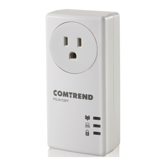
- Page 1 USER MANUAL PG-9172PT G.hn Powerline Adapter with Pass-Through Outlet Version A1.0, August, 2017 261072-000...
- Page 2 Copyright Copyright©2017 Comtrend Corporation. All rights reserved. The information contained herein is proprietary to Comtrend Corporation. No part of this document may be translated, transcribed, reproduced, in any form, or by any means without prior written consent of Comtrend Corporation.
- Page 3 Protect Our Environment This symbol indicates that when the equipment has reached the end of its useful life, it must be taken to a recycling centre and processed separate from domestic waste. The cardboard box, the plastic contained in the packaging, and the parts that make up this PLC can be recycled in accordance with regionally established regulations.
-
Page 4: Table Of Contents
Table of Contents CHAPTER 1 PRODUCT INFORMATION RONT ANEL AND INDICATORS IDE ANEL OTTOM ANEL COVERAGE OW TO UNDERSTAND THE COLORS OINT OINT ETWORK OINT TO ULTIPOINT ETWORK CHAPTER 2 G.HN/POWERLINE SETUP OGGING CHAPTER 3 G.HN INTERFACE ASIC ONFIGURATION NDIM ONFIGURATION NCRYPTION ONFIGURATION VIA CHAPTER 4 IP INTERFACE CONFIG CHAPTER 5 ETHERNET INTERFACE CHAPTER 6 DEVICE INTERFACE ARDWARE INFORMATION OFTWARE INFORMATION ECURITY UPDATE HTTP UPDATE CHAPTER 7 MULTICAST INTERFACE MCAST ONFIGURATION CHAPTER 8 QOS MENU... -
Page 5: Chapter 1 Product Information
Chapter 1 Product Information 1.1 Front Panel and LED indicators COLOR MODE Description The current connection (line rate) is greater Green than 40 Mbps The current connection (line rate) is greater Orange than 20 Mbps and less than 40 Mbps (1). -
Page 6: Side Panel
1.2 Side Panel Item Name Description Press the Security button for more than 2 seconds (until Connection Indicator LED is blinking) and Security release: the “One Button Security Setup” (OBUS) procedure is started and the configuration period is open. Press more than 10 seconds (until all three LED’s are ON) Reset and release: a factory reset is performed. -
Page 7: How To Understand The Coverage Led Colors
1.4 How to understand the COVERAGE LED colors The COVERAGE LED displays quality of the network and provides important information that will provide solutions to common questions, such as why a High Definition (HD) movie is not showing or shows with pixels. The COVERAGE LED indicator will vary its color depending on the estimated speed of the Powerline connection. -
Page 8: Point-To-Point Network
1.5 Point-to-Point Network CASE 1: Estimated throughput is less than 20 Mbps. The COVERAGE LED will • be RED as shown in the following figure: CASE 2: Estimated throughput is greater than 20 Mbps but less than 40 • Mbps. The COVERAGE LED will be ORANGE as shown in the following figure: CASE 3: Estimated throughput is greater than 40 Mbps. -
Page 9: Point To Multipoint Network
1.6 Point to Multipoint Network In the case where the PLC network is composed of three or more adapters, similar situations could arise as with a point-to-point network. CASE 1: The COVERAGE LED in G.hn adapter 2 and G.hn adapter 3 will show •... -
Page 10: Chapter 2 G.hn/Powerline Setup
Chapter 2 G.hn/Powerline Setup PG-9172PT uses DHCP mode. It means PG-9172PT has to get IP address via DHCP server. You should check what IP address is assigned to PG-9172PT via your DHCP server and configure you PC IP address according to the IP address that was assigned to PG-9172PT. -
Page 11: Chapter 3 G.hn Interface
Chapter 3 G.hn Interface 3.1 Basic Configuration MAC Address Displays the MAC address of the device. • Device ID Device ID of this node. • Domain Name string of all nodes in the network. • Force node Type force the modem to have a particular role (END POINT or •... -
Page 12: Ndim Configuration
3.2 NDIM Configuration NDIM mode set to Automatic for enabling automatic DOD selection • functionality and set to Manual for manual configuration of DOD. Domain ID (DOD) manually set the DOD number from 1 to 15 to use a • different preamble seed than the default 0. -
Page 13: Chapter 4 Ip Interface
Chapter 4 IP Interface 4.1 IP config In the IP configuration tab of one G.hn node, the IPv4 and IPv6 settings can be read and changed. IPv4 subsection: DHCPv4 enabled: in the case of choosing ”NO" IP configuration in the •... - Page 14 IPv4 address/netmask: IPv4 address / netmask of this device. • Default Gateway: IPv4 gateway to connect the device to other LAN • segments. DNS: Domain Name Server IP (IPV4). • Additional address #1/2: additional fixed IPv4 addresses that will always •...
-
Page 15: Chapter 5 Ethernet Interface
Chapter 5 Ethernet Interface The Ethernet table shows the status & Info of the Ethernet interface; including Interface, Speed, Duplex, Interface Type, Mode, Internal PHY & Link. Powersaving Ethernet powersaving can be disabled, enabled by Ethernet link or enabled by Ethernet activity;... -
Page 16: Chapter 6 Device Interface
Chapter 6 Device Interface 6.1 Hardware information In this tab, basic information such as MAC Address and Serial Number of the selected node is shown. 6.2 Software information Shows the FW version and system uptime. 6.3 Security The nodes in the network: to change the configuration password string from the default ("paterna") to another;... -
Page 17: Sw Update
6.4 SW update Current loaded firmware version is shown. Any flash section can be upgraded; the first flash section should be selected and after clicking on the "OK" button the corresponding file should be chosen. Usually, a reboot should be performed afterwards to make sure the changes are effective. -
Page 18: Chapter 7 Multicast Interface
Chapter 7 Multicast Interface 7.1 MCAST Configuration In the MCAST Configuration tab of "My Network", IGMP snooping and MLD features can be enabled or disabled. Also, IGMP multicast IP addresses ranges which the G.hn PLC network will sniff; can be configured. IGMP Snooping: Enable or Disable. -
Page 19: Chapter 8 Qos Menu
Chapter 8 QoS menu 8.1 QoS Configuration In the QoS configuration tab, the packet classifier can be managed to define a QoS rule for incoming Ethernet traffic, and assign a priority to be used in the G.hn network. Press the “Ok" button for loading the newly configured settings: QoS CRITERION: a general criterion can be chosen among "None"... - Page 20 Packet detection 2: if second packet detection is also enabled, both, first • and second detection criteria must be accomplished to pass packets to the classification module. Packet classification: up to 8 classification rules can be defined in this • section for packets which have previously been correctly detected.
- Page 21 3 (Third) Critical Applications 4 (second) Video, < 100 ms latency and jitter 5 (second) Voice, < 10 ms latency and jitter 6 (highest) Internetwork Control 7 (highest) Network Control In summary, the sequence of priority queue, (7,6) > (5,4) > (3,0) > (2,1)
-
Page 22: Chapter 9 Vlan Interface
Chapter 9 VLAN Interface 9.1 VLAN Configuration In the VLAN Configuration tab of one G.hn node, a VLAN tag can be added or removed per interface. Enable VLAN Feature: Select No from the drop down menu to disable • completely the VLAN functionality, removing all tags. Set Port as VLAN Trunk: Select Yes from the drop down menu for the •... -
Page 23: Chapter 10 G.hn Spectrum Interface
Chapter 10 G.hn spectrum Interface 10.1 Notches In this tab a table with all configured Notches of selected node will be shown. The table is composed of next columns for every notch: Notch Number, Type of notch, Start Frequency (KHz), Stop Frequency (KHz), Depth (in dB). The first 13 notches (Regulation) are Read Only, RO, in the system and they can be neither removed nor modified. -
Page 24: Chapter 11 Log File Interface
Chapter 11 Log file Interface 11.1 Log File In the Log File configuration the following settings can be read, and changed by clicking on the corresponding "OK" button for the selected node: Enable Log File set to YES for enabling Log File functionality in the node and •... -
Page 25: Chapter 12 Advanced Interface
Chapter 12 Advanced Interface Broadcast suppression: In this tab the broadcast suppression feature can be managed. Broadcast traffic higher than the selected value will be dropped. Hardware Reset: Click on this button to perform a reboot in the node. Factory Reset: Input the password: betera and click the OK button to perform a factory reset.
Need help?
Do you have a question about the PG-9172PT and is the answer not in the manual?
Questions and answers