
Related Manuals for Allen-Bradley MicroLogix 1000


Summary of Contents for Allen-Bradley MicroLogix 1000
- Page 1 - Allen Bradley,Rockwell,plc,servo,drive Allen-Bradley User MicroLogix 1000 Programmable Manual Controllers (Bulletin 1761 Controllers)
- Page 2 The illustrations, charts, sample programs and layout examples shown in this guide are intended solely for purposes of example. Since there are many variables and requirements associated with any particular installation, Allen-Bradley does not assume responsibility or liability (to include intellectual property liability) for actual use based on the examples shown in this publication.
-
Page 3: Table Of Contents
P–6 Allen-Bradley Support ........... . - Page 4 - Allen Bradley,Rockwell,plc,servo,drive MicroLogix 1000 Programmable Controllers User Manual Preface Establishing Communication ..........
- Page 5 efesotomasyon.com - Allen Bradley,Rockwell,plc,servo,drive Table of Contents Equal (EQU) ............7–3 Not Equal (NEQ) .
- Page 6 - Allen Bradley,Rockwell,plc,servo,drive MicroLogix 1000 Programmable Controllers User Manual Preface Data Handling Instructions in the Paper Drilling Machine Application Example ..9–28 Using Program Flow Control Instructions .......
- Page 7 14–6 Calling Allen-Bradley for Assistance ........
- Page 8 - Allen Bradley,Rockwell,plc,servo,drive MicroLogix 1000 Programmable Controllers User Manual Preface Application Example Programs .........
- Page 9 For updated information on automatic protocol switching, see chapter 3, Connecting the System. The MicroLogix 1000 programmable controllers’ VA ratings and power supply inrush specifications have been updated; see appendix A, Hardware Reference. The DF1 Full-Duplex and DH-485 configuration parameters have been updated;...
-
Page 10: Preface
- Allen Bradley,Rockwell,plc,servo,drive MicroLogix 1000 Programmable Controllers User Manual Preface Notes: soc–ii... -
Page 11: Preface
- Allen Bradley,Rockwell,plc,servo,drive Preface Preface Read this preface to familiarize yourself with the rest of the manual. It provides information concerning: who should use this manual the purpose of this manual conventions used in this manual Allen-Bradley support P–1... -
Page 12: Who Should Use This Manual
If you do not, obtain the proper training before using this product. Purpose of this Manual This manual is a reference guide for MicroLogix 1000 controllers. It describes the procedures you use to install, wire, program, and troubleshoot your controller. This... - Page 13 Provides a general overview of the types of Using the Message communication, and explains how to establish Instruction network communication using the message instruction. Troubleshooting Your Explains how to interpret and correct problems Troubleshooting System with your MicroLogix 1000 controller system. P–3...
- Page 14 - Allen Bradley,Rockwell,plc,servo,drive MicroLogix 1000 Programmable Controllers User Manual Preface Chapter Title Contents Provides physical, electrical, environmental, and Appendix A Hardware Reference functional specifications. Programming Explains the system status file and provides Appendix B Reference instruction execution times. Valid Addressing Modes...
- Page 15 - Allen Bradley,Rockwell,plc,servo,drive Preface Related Documentation The following documents contain additional information concerning Allen-Bradley products. To obtain a copy, contact your local Allen-Bradley office or distributor. Document Read this Document Number A procedural manual for technical personnel who use the Allen-Bradley Hand-Held...
-
Page 16: Common Techniques Used In This Manual
Technical Product Assistance If you need to contact Allen-Bradley for technical assistance, please review the information in the Troubleshooting chapter first. Then call your local Allen-Bradley representative. Your Questions or Comments on this Manual... -
Page 17: Installing Your Controller
efesotomasyon.com - Allen Bradley,Rockwell,plc,servo,drive Installing Your Controller Installing Your Controller This chapter shows you how to install your controller system. The only tools you require are a Flat head or Phillips head screwdriver and drill. Topics include: compliance to European Union Directives hardware overview master control relay surge suppressors... -
Page 18: Compliance To European Union Directives
- Allen Bradley,Rockwell,plc,servo,drive MicroLogix 1000 Programmable Controllers User Manual Preface Compliance to European Union Directives If this product has the CE mark it is approved for installation within the European Union and EEA regions. It has been designed and tested to meet the following directives. -
Page 19: Hardware Overview
Installing Your Controller Hardware Overview The MicroLogix 1000 programmable controller is a packaged controller containing a power supply, input circuits, output circuits, and a processor. The controller is available in 10 I/O, 16 I/O and 32 I/O configurations, as well as an analog version with 20 discrete I/O and 5 analog I/O. -
Page 20: Master Control Relay
- Allen Bradley,Rockwell,plc,servo,drive MicroLogix 1000 Programmable Controllers User Manual Preface Master Control Relay A hard-wired master control relay (MCR) provides a reliable means for emergency controller shutdown. Since the master control relay allows the placement of several emergency-stop switches in different locations, its installation is important from a safety standpoint. - Page 21 efesotomasyon.com - Allen Bradley,Rockwell,plc,servo,drive Installing Your Controller Using Emergency-Stop Switches When using emergency-stop switches, adhere to the following points: Do not program emergency-stop switches in the controller program. Any emergency-stop switch should turn off all machine power by turning off the master control relay.
- Page 22 - Allen Bradley,Rockwell,plc,servo,drive MicroLogix 1000 Programmable Controllers User Manual Preface The following illustrations show the Master Control Relay wired in a grounded system. Note The illustrations only show output circuits with MCR protection. In most applications input circuits do not require MCR protection; however, if you need to remove power from all field devices, you must include MCR contacts in series with input power wiring.
- Page 23 efesotomasyon.com - Allen Bradley,Rockwell,plc,servo,drive Installing Your Controller Schematic (Using ANSI/CSA Symbols) 230V ac Disconnect Fuse 230V ac Output Circuits Operation of either of these contacts will Isolation remove power from the adapter external I/O Transformer circuits, stopping machine motion. Master Control Relay (MCR) 115V ac Cat.
-
Page 24: Using Surge Suppressors
- Allen Bradley,Rockwell,plc,servo,drive MicroLogix 1000 Programmable Controllers User Manual Preface Using Surge Suppressors Inductive load devices such as motor starters and solenoids require the use of some type of surge suppression to protect the controller output contacts. Switching inductive loads without surge suppression can significantly reduce the lifetime of relay contacts. - Page 25 Installing Your Controller Suitable surge suppression methods for inductive ac load devices include a varistor, an RC network, or an Allen-Bradley surge suppressor, all shown below. These components must be appropriately rated to suppress the switching transient characteristic of the particular inductive device. See the table on page 1–10 for recommended suppressors.
- Page 26 - Allen Bradley,Rockwell,plc,servo,drive MicroLogix 1000 Programmable Controllers User Manual Preface Recommended Surge Suppressors We recommend the Allen-Bradley surge suppressors shown in the following table for use with Allen-Bradley relays, contactors, and starters. Suppressor Catalog Device Coil Voltage Number Bulletin 509 Motor Starter...
-
Page 27: Safety Considerations
efesotomasyon.com - Allen Bradley,Rockwell,plc,servo,drive Installing Your Controller Safety Considerations Safety considerations are an important element of proper system installation. Actively thinking about the safety of yourself and others, as well as the condition of your equipment, is of primary importance. We recommend reviewing the following safety considerations. - Page 28 - Allen Bradley,Rockwell,plc,servo,drive MicroLogix 1000 Programmable Controllers User Manual Preface Power Distribution There are some points about power distribution that you should know: The master control relay must be able to inhibit all machine motion by removing power to the machine I/O devices when the relay is de-energized.
-
Page 29: Power Considerations
efesotomasyon.com - Allen Bradley,Rockwell,plc,servo,drive Installing Your Controller Power Considerations The following explains power considerations for the micro controllers. Isolation Transformers You may want to use an isolation transformer in the ac line to the controller. This type of transformer provides isolation from your power distribution system and is often used as a step down transformer to reduce line voltage. - Page 30 - Allen Bradley,Rockwell,plc,servo,drive MicroLogix 1000 Programmable Controllers User Manual Preface Loss of Power Source The power supply is designed to withstand brief power losses without affecting the operation of the system. The time the system is operational during power loss is called “program scan hold-up time after loss of power.”...
-
Page 31: Preventing Excessive Heat
efesotomasyon.com - Allen Bradley,Rockwell,plc,servo,drive Installing Your Controller Preventing Excessive Heat For most applications, normal convective cooling keeps the controller within the specified operating range. Ensure that the specified operating range is maintained. Proper spacing of components within an enclosure is usually sufficient for heat dissipation. -
Page 32: Controller Spacing
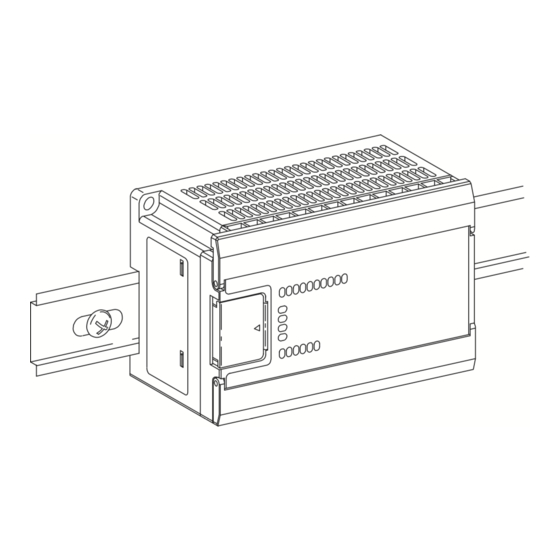
- Allen Bradley,Rockwell,plc,servo,drive MicroLogix 1000 Programmable Controllers User Manual Preface Controller Spacing The following figure shows the recommended minimum spacing for the controller. (Refer to appendix A for controller dimensions.) Explosion Hazard — For Class I, Division 2 applications, this product must be installed in an enclosure. - Page 33 efesotomasyon.com - Allen Bradley,Rockwell,plc,servo,drive Installing Your Controller Using a DIN Rail Use 35 mm (1.38 in.) DIN rails, such as item number 199-DR1 or 1492-DR5 from Bulletin 1492. To install your controller on the DIN rail: 1. Mount your DIN rail. (Make sure that the Side View placement of the controller on the DIN rail Protective Wrap...
- Page 34 - Allen Bradley,Rockwell,plc,servo,drive MicroLogix 1000 Programmable Controllers User Manual Preface Using Mounting Screws To install your controller using mounting screws: Note Leave the protective wrap attached until you are finished wiring the controller. Mounting 1. Use the mounting template from...
-
Page 35: Wiring Your Controller
efesotomasyon.com - Allen Bradley,Rockwell,plc,servo,drive Wiring Your Controller Wiring Your Controller This chapter describes how to wire your controller. Topics include: grounding guidelines sinking and sourcing circuits wiring recommendations wiring diagrams, input voltage ranges, and output voltage ranges 2–1... -
Page 36: Grounding Guidelines
- Allen Bradley,Rockwell,plc,servo,drive MicroLogix 1000 Programmable Controllers User Manual Preface Grounding Guidelines In solid-state control systems, grounding helps limit the effects of noise due to electromagnetic interference (EMI). Use the heaviest wire gauge listed for wiring your controller with a maximum length of 152.4 mm (6 in.). Run the ground connection from the ground screw of the controller (third screw from left on output terminal rung) to the ground bus. -
Page 37: Sinking And Sourcing Circuits
- Allen Bradley,Rockwell,plc,servo,drive Wiring Your Controller Sinking and Sourcing Circuits Any of the MicroLogix 1000 DC inputs can be configured as sinking or sourcing depending on how the DC COM is wired on the MicroLogix. Type Definition The input energizes when high-level voltage is applied to the input terminal Sinking Input (active high). -
Page 38: Wiring Recommendations
- Allen Bradley,Rockwell,plc,servo,drive MicroLogix 1000 Programmable Controllers User Manual Preface 1761-L32BWB, -L32BBB (Wiring Diagrams also apply to 1761-L20BWB-5A, -L16BWB, -L10BWB, -L16BBB.) Sinking Inputs Sourcing Inputs 14–30 VDC 14–30 VDC VDC (+) for Sinking VDC (–) for Sourcing VDC (–) for Sinking... - Page 39 efesotomasyon.com - Allen Bradley,Rockwell,plc,servo,drive Wiring Your Controller Note The diameter of the terminal screw heads is 5.5 mm (0.220 in.). The input and output terminals of the micro controller are designed for the following spade lugs: Call-out Dimension 6.35 mm (0.250 in.) 10.95 mm (0.431 in.) maximum 14.63 mm (0.576 in.) maximum 6.35 mm (0.250 in.)
- Page 40 - Allen Bradley,Rockwell,plc,servo,drive MicroLogix 1000 Programmable Controllers User Manual Preface Remove the protective wrap before applying power to the controller. Failure to remove the wrap may cause the controller to overheat. Calculate the maximum possible current in each power and common wire.
-
Page 41: Wiring Diagrams, Discrete Input And Output Voltage Ranges
efesotomasyon.com - Allen Bradley,Rockwell,plc,servo,drive Wiring Your Controller Wiring Diagrams, Discrete Input and Output Voltage Ranges The following pages show the wiring diagrams, discrete input voltage ranges, and discrete output voltage ranges. Controllers with dc inputs can be wired as either sinking or sourcing configurations. - Page 42 - Allen Bradley,Rockwell,plc,servo,drive MicroLogix 1000 Programmable Controllers User Manual Preface 1761-L32AWA Wiring Diagram 79–132V ac 79–132V ac L2/N L2/N I/10 I/11 I/12 I/13 I/14 I/15 I/16 I/17 I/18 I/19 USED USED 85–264 VAC L2/N O/10 O/11 VAC 2 VDC 1...
- Page 43 efesotomasyon.com - Allen Bradley,Rockwell,plc,servo,drive Wiring Your Controller 1761-L10BWA Wiring Diagram (Sinking Input Configuration) Note: Refer to page 2–3 for additional configuration options. 14–30V dc VDC + VDC + + 24V – USED USED USED USED DC OUT 85–264 VAC L2/N USED USED USED...
- Page 44 - Allen Bradley,Rockwell,plc,servo,drive MicroLogix 1000 Programmable Controllers User Manual Preface 1761-L16BWA Wiring Diagrams (Sinking Input Configuration) Note: Refer to page 2–3 for additional configuration options. 14–30V dc VDC + VDC + + 24V – DC OUT 85–264 VAC L2/N...
- Page 45 efesotomasyon.com - Allen Bradley,Rockwell,plc,servo,drive Wiring Your Controller 1761-L32BWA Wiring Diagram (Sinking Input Configuration) Note: Refer to page 2–3 for additional configuration options. 14-30 V dc VDC + VDC + + 24V – I/10 I/11 I/12 I/13 I/14 I/15 I/16 I/17 I/18 I/19 DC OUT...
- Page 46 - Allen Bradley,Rockwell,plc,servo,drive MicroLogix 1000 Programmable Controllers User Manual Preface 1761-L10BWB Wiring Diagram (Sinking Input Configuration) Note: Refer to page 2–4 for additional configuration options. 14–30 VDC 14–30 VDC VDC + VDC + USED USED USED USED USED USED DC IN + 24V –...
- Page 47 efesotomasyon.com - Allen Bradley,Rockwell,plc,servo,drive Wiring Your Controller 1761-L16BWB Wiring Diagram (Sinking Input Configuration) Note: Refer to page 2–4 for additional configuration options. 14–30V dc 14–30V dc VDC + VDC + USED USED DC IN + 24V – VAC 1 VDC 2 VDC 3 VDC 4 VAC 1...
- Page 48 - Allen Bradley,Rockwell,plc,servo,drive MicroLogix 1000 Programmable Controllers User Manual Preface 1761-L32BWB Wiring Diagram (Sinking Input Configuration) Note: Refer to page 2–4 for additional configuration options. Sinking Configuration Sourcing Configuration 14–30V dc 14–30V dc VDC + VDC + I/10 I/11...
- Page 49 efesotomasyon.com - Allen Bradley,Rockwell,plc,servo,drive Wiring Your Controller 1761-L32AAA Wiring Diagram 79–132V ac 79–132V ac L2/N L2/N I/10 I/11 I/12 I/13 I/14 I/15 I/16 I/17 I/18 I/19 USED USED 85–264 VAC L2/N O/10 O/11 VAC 1 VAC 2 VAC 3 VAC 4 VAC 1 VAC 2 VAC 3...
- Page 50 - Allen Bradley,Rockwell,plc,servo,drive MicroLogix 1000 Programmable Controllers User Manual Preface 1761-L16BBB Wiring Diagrams (Sinking Input Configuration) Note: Refer to page 2–4 for additional configuration options. 14–30V dc 14–30V dc VDC + VDC + USED USED Sourcing Outputs DC IN + 24V –...
- Page 51 efesotomasyon.com - Allen Bradley,Rockwell,plc,servo,drive Wiring Your Controller 1761-L32BBB Wiring Diagram (Sinking Input Configuration) Note: Refer to page 2–4 for additional configuration options. Sinking Configuration Sourcing Configuration 14–30V dc 14–30V dc VDC + VDC + I/10 I/11 I/12 I/13 I/14 I/15 I/16 I/17 I/18 I/19...
- Page 52 - Allen Bradley,Rockwell,plc,servo,drive MicroLogix 1000 Programmable Controllers User Manual Preface 1761-L20AWA-5A Wiring Diagram Note: Refer to pages 2–21 through 2–23 for additional information on analog wiring. Analog 79–132V ac 79–132V ac Channels L2/N L2/N I/10 I/11 IA/0 IA/1 IA/2...
- Page 53 efesotomasyon.com - Allen Bradley,Rockwell,plc,servo,drive Wiring Your Controller 1761-L20BWA-5A Wiring Diagram (Sinking Input Configuration) Note: Refer to page 2–3 for additional discrete configuration options. Refer to pages 2–21 through 2–23 for additional information on analog wiring. Analog 14–30V dc Channels VDC (–) VDC (+) VDC (+) VDC (–)
- Page 54 - Allen Bradley,Rockwell,plc,servo,drive MicroLogix 1000 Programmable Controllers User Manual Preface 1761-L20BWB-5A Wiring Diagram (Sinking Input Configuration) Note: Refer to page 2–4 for additional discrete configuration options. Refer to pages 2–21 through 2–23 for additional information on analog wiring. Analog 14–30V dc...
-
Page 55: Minimizing Electrical Noise On Analog Controllers
A system may malfunction due to a change in the operating environment after a period of time. We recommend periodically checking system operation, particularly when new machinery or other noise sources are installed near the MicroLogix 1000 system. Grounding Your Analog Cable Use shielded communication cable (Belden #8761). -
Page 56: Wiring Your Analog Channels
- Allen Bradley,Rockwell,plc,servo,drive MicroLogix 1000 Programmable Controllers User Manual Preface Wiring Your Analog Channels Analog input circuits can monitor current and voltage signals and convert them to serial digital data. The analog output can support either a voltage or a current function. -
Page 57: Analog Voltage And Current Input And Output Ranges
efesotomasyon.com - Allen Bradley,Rockwell,plc,servo,drive Wiring Your Controller Analog Voltage and Current Input and Output Ranges Analog Voltage Input Range –10.5V dc 10.5V dc 24V dc –24V dc É É É É É É É É É É É É É É É É... -
Page 58: Wiring Your Controller For High-Speed Counter Applications
- Allen Bradley,Rockwell,plc,servo,drive MicroLogix 1000 Programmable Controllers User Manual Preface Wiring Your Controller for High-Speed Counter Applications To wire the controller for high-speed counter applications use input terminals I/0, I/1, I/2, and I/3. Refer to chapter 12 for information on using the high-speed counter. -
Page 59: Connecting The System
efesotomasyon.com - Allen Bradley,Rockwell,plc,servo,drive Connecting the System Connecting the System This chapter describes how to wire your controller system. The method you use and cabling required to connect your controller depends on what type of system you are employing. This chapter also describes how the controller establishes communication with the appropriate network. -
Page 60: Connecting The Df1 Protocol
MicroLogix 1000 Programmable Controllers User Manual Preface Connecting the DF1 Protocol There are two ways to connect the MicroLogix 1000 programmable controller to your personal computer using the DF1 protocol: using an isolated point-to-point connection, or using a modem. Descriptions of these methods follow. - Page 61 9-Pin Using a Modem You can also use modems to connect a personal computer to one MicroLogix 1000 controller (using DF1 full-duplex protocol) or to multiple controllers (using DF1 half-duplex protocol), as shown in the illustration that follows. Do not attempt to use DH-485 protocol through modems under any circumstance.
- Page 62 - Allen Bradley,Rockwell,plc,servo,drive MicroLogix 1000 Programmable Controllers User Manual Preface Modem Cable Personal Computer Modem DF1 full-duplex protocol (to 1 controller) DF1 half-duplex master protocol (to multiple controllers) Optical Isolator (recommended) Micro Controller 1761-CBL-PM02 Modem DF1 full-duplex protocol or...
-
Page 63: Connecting To A Dh-485 Network
- Allen Bradley,Rockwell,plc,servo,drive Connecting the System Connecting to a DH-485 Network Note Only Series C or later MicroLogix 1000 discrete controllers and all MicroLogix 1000 analog controllers support DH-485 network connections. MicroLogix 1000 (Series C or later discrete or MicroLogix 1000 analog) - Page 64 Allow enough extra cable to prevent chafing and kinking in the cable. Use these instructions for wiring the Belden #3106A or #9842 cable. (If you are using standard Allen-Bradley cables, see the Cable Selection Guide on page 3–12.) 3–6...
- Page 65 efesotomasyon.com - Allen Bradley,Rockwell,plc,servo,drive Connecting the System Connecting the Communication Cable to the DH-485 Connector Note A daisy-chained network is recommended. We do not recommend the following: Belden Belden Belden #3106A or #3106A or #3106A or #9842 #9842 #9842 Connector Connector Connector Incorrect...
- Page 66 - Allen Bradley,Rockwell,plc,servo,drive MicroLogix 1000 Programmable Controllers User Manual Preface The table below shows connections for Belden #3106A. For this Wire/Pair Connect this Wire To this Terminal Shield/Drain Non-jacketed Terminal 2 – Shield Blue Blue Terminal 3 – (Common) White with Orange Stripe Terminal 4 –...
-
Page 67: Connecting The Aic
In addition, if a MicroLogix 1000 controller powers an AIC+ that is connected to the network, network activity will not be disrupted should the MicroLogix 1000 controller be removed from the AIC+. The figure that follows shows the external wiring connections and specifications of the AIC+. - Page 68 MicroLogix 1000 provides power to the AIC+ via port 2.) DH-485 Network Connection MicroLogix 1000 (Series C or later discrete and all analog) PC to port 1 connection from or port 2 port 1 or port 2...
- Page 69 24V dc (Not needed in this configuration User supplied modem cable since the MicroLogix 1000 provides power to the AIC+ via port 2.) For additional information on connections using the AIC+, see the Advanced Interface Converter (AIC+) and DeviceNet Interface (DNI) Installation Instructions, Publication 1761-5.11.
- Page 70 - Allen Bradley,Rockwell,plc,servo,drive MicroLogix 1000 Programmable Controllers User Manual Preface Cable Selection Guide 1747-CP3 1761-CBL-AC00 External Power Selection Power Supply Cable Length Connections from to AIC+ Switch Setting Required 1747-CP3 7 7 C 3m (9.8 ft) SLC 5/03 or SLC 5/04 processor, channel 0...
- Page 71 45 cm (17.7 in) SLC 5/03 or SLC 5/04 processors, channel 0 port 2 external 2m (6.5 ft) 1761-CBL-PM02 external MicroLogix 1000 port 1 PanelView 550 through NULL modem adapter port 2 external DTAM Plus / DTAM Micro port 2...
- Page 72 If you are making a cable to connect to port 2, you must configure your cable to connect to the Allen-Bradley cable shown above. On port 1, pin 4 is electronically jumpered to pin 6. Whenever the AIC+ is powered on, pin 4 will match the state of pin 6.
- Page 73 This connection must be made whether or not an external 24V dc supply is used. In normal operation with the MicroLogix 1000 programmable controller connected to port 2 of the AIC+, the controller powers the AIC+. Any AIC+ not connected to a controller requires a 24V dc power supply.
- Page 74 Installing and Attaching the AIC+ Take care when installing the AIC+ in an enclosure so that the cable connecting the MicroLogix 1000 controller to the AIC+ does not interfere with the enclosure door. Carefully plug the terminal block into the DH-485 port on the AIC+ you are putting on the network.
-
Page 75: Establishing Communication
Primary Protocol bit, S:0/10. The default setting for this bit is DF1 (0). If the primary protocol bit is set to DF1, the MicroLogix 1000 controller will attempt to connect using the configured DF1 protocol; either full-duplex or half-duplex slave. -
Page 76: Devicenet Communications
- Allen Bradley,Rockwell,plc,servo,drive MicroLogix 1000 Programmable Controllers User Manual Preface DeviceNet Communications You can also connect a MicroLogix to a DeviceNet network using the DeviceNet Interface (DNI), catalog number 1761-NET-DNI. For additional information on connecting the DNI, see the Advanced Interface Converter (AIC+) and DeviceNet Interface (DNI) Installation Instructions, Publication 1761-5.11. -
Page 77: Programming Overview
- Allen Bradley,Rockwell,plc,servo,drive Programming Overview Programming Overview This chapter explains how to program the MicroLogix 1000 programmable controller. Read this chapter for basic information about: principles of machine control understanding file organization and addressing understanding how processor files are stored and accessed... -
Page 78: Principles Of Machine Control
- Allen Bradley,Rockwell,plc,servo,drive MicroLogix 1000 Programmable Controllers User Manual Preface Principles of Machine Control The controller consists of a built-in power supply, central processing unit (CPU), inputs, which you wire to input devices (such as pushbuttons, proximity sensors, limit switches), and outputs, which you wire to output devices (such as motor starters, solid-state relays, and indicator lights). - Page 79 efesotomasyon.com - Allen Bradley,Rockwell,plc,servo,drive Programming Overview With the logic program entered into the controller, placing the controller in the Run mode initiates an operating cycle. The controller’s operating cycle consists of a series of operations performed sequentially and repeatedly, unless altered by your program logic.
-
Page 80: Understanding File Organization
- Allen Bradley,Rockwell,plc,servo,drive MicroLogix 1000 Programmable Controllers User Manual Preface Understanding File Organization The processor provides control through the use of a program you create, called a processor file. This file contains other files that break your program down into more manageable parts. - Page 81 efesotomasyon.com - Allen Bradley,Rockwell,plc,servo,drive Programming Overview Program Files Program files contain controller information, the main ladder program, interrupt subroutines, and any subroutine programs. These files are: System Program (file 0) – This file contains various system related information and user-programmed information such as processor type, I/O configuration, processor file name, and password.
-
Page 82: Understanding How Processor Files Are Stored And Accessed
Understanding How Processor Files are Stored and Accessed The MicroLogix 1000 programmable controller uses two devices for storing processor files: RAM and EEPROM. The RAM provides easy access storage (i.e., its data is lost on a power down), while the EEPROM provides long-term storage (i.e., its data is not lost on a power down). - Page 83 efesotomasyon.com - Allen Bradley,Rockwell,plc,servo,drive Programming Overview Download When the processor file is downloaded to the micro controller, it is first stored in the volatile RAM. It is then transferred to the non-volatile EEPROM, where it is stored as both backup data and retentive data. EEPROM Backup Data CPU Workspace...
- Page 84 - Allen Bradley,Rockwell,plc,servo,drive MicroLogix 1000 Programmable Controllers User Manual Preface Power Down When a power down occurs, only the retentive data is transferred from the RAM to the EEPROM. (The program files do not need to be saved to the EEPROM since they cannot be modified during normal operation.) If for some reason power is lost...
- Page 85 efesotomasyon.com - Allen Bradley,Rockwell,plc,servo,drive Programming Overview If retentive data was lost on power down, the backup data from the EEPROM is transferred to the RAM and used as the retentive data. In addition, status file bit S2:5/8 (retentive data lost) is set and a recoverable major error occurs when going to run.
-
Page 86: Addressing Data Files
- Allen Bradley,Rockwell,plc,servo,drive MicroLogix 1000 Programmable Controllers User Manual Preface Addressing Data Files For the purposes of addressing, each data file type is identified by a letter (identifier) and a file number. File File Identifier Type Number Output Input... - Page 87 efesotomasyon.com - Allen Bradley,Rockwell,plc,servo,drive Programming Overview You assign logical addresses to instructions from the highest level (element) to the lowest level (bit). Addressing examples are shown in the table below. To specify the Use these parameters: address of a: Word within an integer file File Type File Number File Delimiter...
- Page 88 - Allen Bradley,Rockwell,plc,servo,drive MicroLogix 1000 Programmable Controllers User Manual Preface You can also address at the bit level using mnemonics for timer, counter, or control data types. The available mnemonics depend on the type of data. See chapters 6 through 13 for more information.
- Page 89 efesotomasyon.com - Allen Bradley,Rockwell,plc,servo,drive Programming Overview In this example, the processor uses the following addresses: Value: Base Address: Offset Value in S:24 Offset Address: Source N7:10 N7:20 Destination N7:50 N7:60 Addressing File Instructions – Using the File Indicator (#) The file instructions below manipulate data table files. These files are addressed with the # sign.
-
Page 90: Applying Ladder Logics To Your Schematics
- Allen Bradley,Rockwell,plc,servo,drive MicroLogix 1000 Programmable Controllers User Manual Preface When entering values into an instruction or data table element, you can specify the radix of your entry using the “&” special operator. The radixes that can be used to enter data into an instruction or data table element are: Integer (&N) -
Page 91: Developing Your Logic Program - A Model
efesotomasyon.com - Allen Bradley,Rockwell,plc,servo,drive Programming Overview The programming device allows you to enter a ladder logic program into the micro controller. In the following illustration, the electromechanical circuit shows PB1 and PB2, two pushbuttons, wired in series with an alarm horn. PB1 is a normally open pushbutton, and PB2 is normally closed. - Page 92 - Allen Bradley,Rockwell,plc,servo,drive MicroLogix 1000 Programmable Controllers User Manual Preface Program Development Program Development Process Checklist Prepare a general description of how you want your Design automated process to operate. Functional Specification Identify the hardware requirements. Perform Match inputs and outputs with actions of the process.
-
Page 93: Using Analog
- Allen Bradley,Rockwell,plc,servo,drive Using Analog Using Analog This chapter describes the operation of the MicroLogix 1000 analog controllers. Topics include: I/O Image I/O Configuration Input Filter and Update Times Converting Analog Data 5–1... -
Page 94: I/O Image
- Allen Bradley,Rockwell,plc,servo,drive MicroLogix 1000 Programmable Controllers User Manual Preface I/O Image The input and output image files of the MicroLogix 1000 analog controllers have the following format: Address Input Image Output Image Address I:0.0 Discrete Input Word 0 Discrete Output Word 0 O:0.0... -
Page 95: I/O Configuration
efesotomasyon.com - Allen Bradley,Rockwell,plc,servo,drive Using Analog I/O Configuration The analog input channels are single-ended (unipolar) circuits and can be individually enabled or disabled. The default is all input channels enabled. The two voltage inputs accept 10.5V dc, and the two current inputs accept 21 mA. - Page 96 - Allen Bradley,Rockwell,plc,servo,drive MicroLogix 1000 Programmable Controllers User Manual Preface The total update time for each channel is a combination of the Update Time and the Settling Time. When more than one analog input channel is enabled, the maximum update for each channel is equal to one ladder scan time plus the channel’s Update...
-
Page 97: Converting Analog Data
efesotomasyon.com - Allen Bradley,Rockwell,plc,servo,drive Using Analog Converting Analog Data The analog input circuits are able to monitor current and voltage signals and convert them to digital data. There are six terminals assigned to the input channels that provide two voltage inputs, two current inputs and two return signals (commons). The analog outputs can support either a current or voltage function. - Page 98 - Allen Bradley,Rockwell,plc,servo,drive MicroLogix 1000 Programmable Controllers User Manual Preface 10.5V input value = input voltage(V) 32,767 The Input Value is the decimal value of the word in the input image for the corresponding analog input. For example, if an input value of 16,021 is in the input image, the calculated value is: 10.5V...
-
Page 99: Using Basic Instructions
efesotomasyon.com - Allen Bradley,Rockwell,plc,servo,drive Using Basic Instructions Using Basic Instructions This chapter contains general information about the basic instructions and explains how they function in your application program. Each of the basic instructions includes information on: what the instruction symbol looks like typical execution time for the instruction how to use the instruction In addition, the last section contains an application example for a paper drilling... -
Page 100: About The Basic Instructions
- Allen Bradley,Rockwell,plc,servo,drive MicroLogix 1000 Programmable Controllers User Manual Preface Timer/Counter Instructions Instruction Purpose Purpose Page Page Mnemonic Name Timer On-Delay Counts timebase intervals when the instruction is 6–11 true. Timer Off-Delay Counts timebase intervals when the instruction is 6–12... -
Page 101: Bit Instructions Overview
efesotomasyon.com - Allen Bradley,Rockwell,plc,servo,drive Using Basic Instructions Bit Instructions Overview These instructions operate on a single bit of data. During operation, the controller may set or reset the bit, based on the logical continuity of ladder rungs. You can address a bit as many times as your program requires. Note Using the same address with multiple output instructions is not recommended. -
Page 102: Examine If Closed (Xic)
- Allen Bradley,Rockwell,plc,servo,drive MicroLogix 1000 Programmable Controllers User Manual Preface Examine if Closed (XIC) Use the XIC instruction in your ladder program to determine if a bit is On. When the instruction is executed, if the bit addressed is on (1), then the instruction is evaluated as true. -
Page 103: Output Energize (Ote)
efesotomasyon.com - Allen Bradley,Rockwell,plc,servo,drive Using Basic Instructions Output Energize (OTE) Use an OTE instruction in your ladder program to turn On a bit when rung conditions are evaluated as true. Execution Times An example of a device that turns on or off is an output wired to a pilot light (µsec) when: (addressed as O0:0/4). - Page 104 - Allen Bradley,Rockwell,plc,servo,drive MicroLogix 1000 Programmable Controllers User Manual Preface Using OTL When you assign an address to the OTL instruction that corresponds to the address of a physical output, the output device wired to this screw terminal is energized when the bit is set (turned on or enabled).
-
Page 105: One-Shot Rising (Osr)
efesotomasyon.com - Allen Bradley,Rockwell,plc,servo,drive Using Basic Instructions One-Shot Rising (OSR) The OSR instruction is a retentive input instruction that triggers an event to occur [OSR] one time. Use the OSR instruction when an event must start based on the change of state of the rung from false to true. -
Page 106: Timer Instructions Overview
- Allen Bradley,Rockwell,plc,servo,drive MicroLogix 1000 Programmable Controllers User Manual Preface Timer Instructions Overview Each timer address is made of a 3-word element. Word 0 is the control word, word 1 stores the preset value, and word 2 stores the accumulated value. - Page 107 efesotomasyon.com - Allen Bradley,Rockwell,plc,servo,drive Using Basic Instructions Timer Accuracy Timer accuracy refers to the length of time between the moment a timer instruction is enabled and the moment the timed interval is complete. Timing accuracy is –0.01 to +0 seconds, with a program scan of up to 2.5 seconds. The 1-second timer maintains accuracy with a program scan of up to 1.5 seconds.
- Page 108 - Allen Bradley,Rockwell,plc,servo,drive MicroLogix 1000 Programmable Controllers User Manual Preface Addressing Examples T4:0/15 or T4:0/EN Enable bit T4:0/14 or T4:0/TT Timer timing bit T4:0/13 or T4:0/DN Done bit T4:0.1 or T4:0.PRE Preset value of the timer T4:0.2 or T4:0.ACC Accumulator value of the timer T4:0.1/0 or T4:0.PRE/0 Bit 0 of the preset value...
-
Page 109: Timer On-Delay (Ton)
efesotomasyon.com - Allen Bradley,Rockwell,plc,servo,drive Using Basic Instructions Timer On-Delay (TON) Use the TON instruction to delay the turning on or off of an output. The TON TIMER ON DELAY (EN) Timer instruction begins to count timebase intervals when rung conditions become true. Time Base (DN) Preset... -
Page 110: Timer Off-Delay (Tof)
- Allen Bradley,Rockwell,plc,servo,drive MicroLogix 1000 Programmable Controllers User Manual Preface Timer Off-Delay (TOF) Use the TOF instruction to delay turning on or off an output. The TOF instruction TIMER OFF DELAY (EN) Timer begins to count timebase intervals when the rung makes a true-to-false transition. - Page 111 efesotomasyon.com - Allen Bradley,Rockwell,plc,servo,drive Using Basic Instructions On returning to the REM Run or REM Test mode, the following can happen: Condition Result If the rung is true: TT bit is reset. DN bit remains set. EN bit is set. ACC value is reset.
-
Page 112: Retentive Timer (Rto)
- Allen Bradley,Rockwell,plc,servo,drive MicroLogix 1000 Programmable Controllers User Manual Preface Retentive Timer (RTO) Use the RTO instruction to turn an output on or off after its timer has been on for a RETENTIVE TIMER ON (EN) Timer preset time interval. The RTO instruction is a retentive instruction that lets the timer... -
Page 113: Counter Instructions Overview
efesotomasyon.com - Allen Bradley,Rockwell,plc,servo,drive Using Basic Instructions On returning to the REM Run or REM Test mode or when power is restored, the following can happen: Condition Result TT bit remains set. If the rung is true: EN bit remains set. ACC value remains the same and resumes incrementing. - Page 114 - Allen Bradley,Rockwell,plc,servo,drive MicroLogix 1000 Programmable Controllers User Manual Preface Entering Parameters Accumulator Value (ACC) This is the number of false-to-true transitions that have occurred since the counter was last reset. Preset Value (PRE) Specifies the value which the counter must reach before the controller sets the done bit.
- Page 115 efesotomasyon.com - Allen Bradley,Rockwell,plc,servo,drive Using Basic Instructions Addressing Examples C5:0/15 or C5:0/CU Count up enable bit C5:0/14 or C5:0/CD Count down enable bit C5:0/13 or C5:0/DN Done bit C5:0/12 or C5:0/OV Overflow bit C5:0/11 or C5:0/UN Underflow bit C5:0/10 or C5:0/UA Update accumulator bit C5:0.1 or C5:0.PRE Preset value of the counter C5:0.2 or C5:0.ACC Accumulator value of the counter C5:0.1/0 or C5:0.PRE/0 Bit 0 of the preset value...
-
Page 116: Count Up (Ctu)
- Allen Bradley,Rockwell,plc,servo,drive MicroLogix 1000 Programmable Controllers User Manual Preface Count Up (CTU) The CTU is an instruction that counts false-to-true rung transitions. Rung COUNT UP (CU) Counter transitions can be caused by events occurring in the program (from internal logic or... -
Page 117: Count Down (Ctd)
efesotomasyon.com - Allen Bradley,Rockwell,plc,servo,drive Using Basic Instructions Count Down (CTD) The CTD is a retentive output instruction that counts false-to-true rung transitions. COUNT DOWN (CD) Counter Rung transitions can be caused by events occurring in the program such as parts Preset (DN) Accum... -
Page 118: Reset (Res)
- Allen Bradley,Rockwell,plc,servo,drive MicroLogix 1000 Programmable Controllers User Manual Preface Reset (RES) Use a RES instruction to reset a timer or counter. When the RES instruction is (RES) executed, it resets the data having the same address as the RES instruction. -
Page 119: Basic Instructions In The Paper Drilling Machine Application Example
efesotomasyon.com - Allen Bradley,Rockwell,plc,servo,drive Using Basic Instructions Basic Instructions in the Paper Drilling Machine Application Example This section provides ladder rungs to demonstrate the use of basic instructions. The rungs are part of the paper drilling machine application example described in appendix E. - Page 120 - Allen Bradley,Rockwell,plc,servo,drive MicroLogix 1000 Programmable Controllers User Manual Preface Rung 2:3 Starts the conveyor in motion when the start button is pressed. However, another condition must also be met before we start the conveyor: the drill must be in its fully retracted position (home).
- Page 121 efesotomasyon.com - Allen Bradley,Rockwell,plc,servo,drive Using Basic Instructions Adding File 6 This subroutine controls the up and down motion of the drill for the paper drilling machine. Drill Home Drill On/Off O/1 Drill Retract O/2 Drill Forward O/3 Drill Depth Rung 6:0 This section of ladder logic controls the up/down motion of the drill for the book drilling machine.
- Page 122 - Allen Bradley,Rockwell,plc,servo,drive MicroLogix 1000 Programmable Controllers User Manual Preface Rung 6:2 When the drill is retracting (after drilling a hole), the body of the drill actuates the DRILL HOME limit switch. When this happens the DRILL RETRACT signal is turned off, the DRILL SEQUENCE START bit is turned off to indicate the drilling process is complete, and the conveyor is restarted.
-
Page 123: Using Comparison Instructions
efesotomasyon.com - Allen Bradley,Rockwell,plc,servo,drive Using Comparison Instructions Using Comparison Instructions This chapter contains general information about comparison instructions and explains how they function in your application program. Each of the comparison instructions includes information on: what the instruction symbol looks like typical execution time for the instruction how to use the instruction In addition, the last section contains an application example for a paper drilling... -
Page 124: About The Comparison Instructions
- Allen Bradley,Rockwell,plc,servo,drive MicroLogix 1000 Programmable Controllers User Manual Preface About the Comparison Instructions Comparison instructions are used to test pairs of values to condition the logical continuity of a rung. As an example, suppose a LES instruction is presented with two values. -
Page 125: Equal (Equ)
efesotomasyon.com - Allen Bradley,Rockwell,plc,servo,drive Using Comparison Instructions Equal (EQU) Use the EQU instruction to test whether two values are equal. If source A and EQUAL Source A source B are equal, the instruction is logically true. If these values are not equal, the Source B instruction is logically false. -
Page 126: Less Than Or Equal (Leq)
- Allen Bradley,Rockwell,plc,servo,drive MicroLogix 1000 Programmable Controllers User Manual Preface Less Than or Equal (LEQ) Use the LEQ instruction to test whether one value (source A) is less than or equal to LESS THAN OR EQUAL Source A another (source B). If the value at source A is less than or equal to the value of Source B source B, the instruction is logically true. -
Page 127: Masked Comparison For Equal (Meq)
efesotomasyon.com - Allen Bradley,Rockwell,plc,servo,drive Using Comparison Instructions Masked Comparison for Equal (MEQ) Use the MEQ instruction to compare data of a source address with data of a MASKED EQUAL Source reference address. Use of this instruction allows portions of the data to be masked Mask by a separate word. -
Page 128: Limit Test (Lim)
- Allen Bradley,Rockwell,plc,servo,drive MicroLogix 1000 Programmable Controllers User Manual Preface Limit Test (LIM) Use the LIM instruction to test for values within or outside a specified range, LIMIT TEST Low Lim depending on how you set the limits. Test... - Page 129 efesotomasyon.com - Allen Bradley,Rockwell,plc,servo,drive Using Comparison Instructions If the Low Limit has a value greater than the High Limit, the instruction is false when the Test value is between the limits. If the Test value is equal to either limit or outside the limits, the instruction is true, as shown below.
-
Page 130: Comparison Instructions In The Paper Drilling Machine Application Example
- Allen Bradley,Rockwell,plc,servo,drive MicroLogix 1000 Programmable Controllers User Manual Preface Comparison Instructions in the Paper Drilling Machine Application Example This section provides ladder rungs to demonstrate the use of comparison instructions. The rungs are part of the paper drilling machine application example described in appendix E. - Page 131 efesotomasyon.com - Allen Bradley,Rockwell,plc,servo,drive Using Comparison Instructions Beginning a Subroutine in File 7 This section of ladder keeps track of the total inches of paper the current drill bit has drilled through. As the current bit wears out, a light illuminates on the operator panel, below, to warn the operator to change the drill bit.
- Page 132 - Allen Bradley,Rockwell,plc,servo,drive MicroLogix 1000 Programmable Controllers User Manual Preface 1/4 in. 102,000 Thousands 1/4 in. increments | | have occurred | +GEQ–––––––––––––––+ +–+GRTR THAN OR EQUAL+–––––––––––––––––––––––––––––––––( )–––––+ | | |Source A N7:11| | |Source B 102| | +––––––––––––––––––+ 1/4 in.
-
Page 133: Using Math Instructions
efesotomasyon.com - Allen Bradley,Rockwell,plc,servo,drive Using Math Instructions Using Math Instructions This chapter contains general information about math instructions and explains how they function in your logic program. Each of the math instructions includes information on: what the instruction symbol looks like typical execution time for the instruction how to use the instruction In addition, the last section contains an application example for a paper drilling... -
Page 134: About The Math Instructions
- Allen Bradley,Rockwell,plc,servo,drive MicroLogix 1000 Programmable Controllers User Manual Preface About the Math Instructions These instructions perform the familiar four function math operations. The majority of the instructions take two input values, perform the specified arithmetic function, and output the result to an assigned memory location. - Page 135 efesotomasyon.com - Allen Bradley,Rockwell,plc,servo,drive Using Math Instructions Overflow Trap Bit, S:5/0 Minor error bit (S:5/0) is set upon detection of a mathematical overflow or division by zero. If this bit is set upon execution of an END statement or a Temporary End (TND) instruction, the recoverable major error code 0020 is declared.
-
Page 136: Add (Add)
- Allen Bradley,Rockwell,plc,servo,drive MicroLogix 1000 Programmable Controllers User Manual Preface Add (ADD) Use the ADD instruction to add one value (source A) to another value (source B) Source A and place the result in the destination. Source A and B can either be a word address Source B or constant. -
Page 137: Subtract (Sub)
efesotomasyon.com - Allen Bradley,Rockwell,plc,servo,drive Using Math Instructions Subtract (SUB) Use the SUB instruction to subtract one value (Source B) from another (source A) SUBTRACT Source A and place the result in the destination. Source A and B can either be a word address Source B or constant. -
Page 138: 32-Bit Addition And Subtraction
- Allen Bradley,Rockwell,plc,servo,drive MicroLogix 1000 Programmable Controllers User Manual Preface 32-Bit Addition and Subtraction You have the option of performing 16-bit or 32-bit signed integer addition and subtraction. This is facilitated by status file bit S:2/14 (math overflow selection bit). - Page 139 efesotomasyon.com - Allen Bradley,Rockwell,plc,servo,drive Using Math Instructions Add 16–bit value B3:1 to 32–bit value B3:3 B3:2 Add Operation Binary Decimal Addend B3:3 B3:2 0000 0000 0000 0011 0001 1001 0100 0000 0003 1940 203,072 Addend B3:1 0101 0101 1010 1000 55A8 21,928 0000 0000 0000 0011 0110 1110 1110 1000...
-
Page 140: Multiply (Mul)
- Allen Bradley,Rockwell,plc,servo,drive MicroLogix 1000 Programmable Controllers User Manual Preface Multiply (MUL) Use the MUL instruction to multiply one value (source A) by another (source B) MULTIPLY Source A and place the result in the destination. Source A and B can either be a word address Source B or constant. -
Page 141: Divide (Div)
efesotomasyon.com - Allen Bradley,Rockwell,plc,servo,drive Using Math Instructions Divide (DIV) Use the DIV instruction to divide one value (source A) by another (source B), and DIVIDE Source A place the rounded quotient in the destination. If the remainder is 0.5 or greater, the Source B destination is rounded up. -
Page 142: Double Divide (Ddv)
- Allen Bradley,Rockwell,plc,servo,drive MicroLogix 1000 Programmable Controllers User Manual Preface Double Divide (DDV) The 32-bit content of the math register is divided by the 16-bit source value and the DOUBLE DIVIDE Source rounded quotient is placed in the destination. If the remainder is 0.5 or greater, the Dest destination is rounded up. -
Page 143: Clear (Clr)
efesotomasyon.com - Allen Bradley,Rockwell,plc,servo,drive Using Math Instructions Clear (CLR) Use the CLR instruction to set the destination to zero. All of the bits reset. CLEAR Dest Execution Times (µsec) when: True False 20.80 4.25 Updates to Arithmetic Status Bits With this Bit: The Controller: S:0/0 Carry (C) -
Page 144: Scale Data (Scl)
- Allen Bradley,Rockwell,plc,servo,drive MicroLogix 1000 Programmable Controllers User Manual Preface Scale Data (SCL) When this instruction is true, the value at the source address is multiplied by the rate SCALE Source value. The rounded result is added to the offset value and placed in the destination. - Page 145 - Allen Bradley,Rockwell,plc,servo,drive Using Math Instructions The following example takes a 0V to 10V analog input from a MicroLogix 1000 analog controller and scales the raw input data to a value between 0 and 100%. The input value range is 0V to 10V which corresponds to 0 to 31,207 counts. The scaled value range is 0 to 100 percent.
-
Page 146: Math Instructions In The Paper Drilling Machine Application Example
- Allen Bradley,Rockwell,plc,servo,drive MicroLogix 1000 Programmable Controllers User Manual Preface Math Instructions in the Paper Drilling Machine Application Example This section provides ladder rungs to demonstrate the use of math instructions. The rungs are part of the paper drilling machine application example described in appendix E. - Page 147 efesotomasyon.com - Allen Bradley,Rockwell,plc,servo,drive Using Math Instructions Rung 7:6 When the number of 1/4 in. increments surpasses 1000, finds out how many increments are past 1000 and stores in N7:20. Add 1 to the total of 1000 1/4 in. increments, and re-initializes the 1/4 in. increments accumulator to how many increments were beyond 1000.
- Page 148 - Allen Bradley,Rockwell,plc,servo,drive MicroLogix 1000 Programmable Controllers User Manual Preface Notes: 8–16...
-
Page 149: Using Data Handling Instructions
efesotomasyon.com - Allen Bradley,Rockwell,plc,servo,drive Using Data Handling Instructions Using Data Handling Instructions This chapter contains general information about the data handling instructions and explains how they function in your application program. Each of the instructions includes information on: what the instruction symbol looks like typical execution time for the instruction how to use the instruction In addition, the last section contains an application example for a paper drilling... -
Page 150: About The Data Handling Instructions
- Allen Bradley,Rockwell,plc,servo,drive MicroLogix 1000 Programmable Controllers User Manual Preface Instruction Purpose Purpose Page Page Mnemonic Name Move Moves the source value to the destination. 9–15 Masked Move Moves data from a source location to a selected 9–16 portion of the destination. -
Page 151: Convert To Bcd (Tod)
efesotomasyon.com - Allen Bradley,Rockwell,plc,servo,drive Using Data Handling Instructions Convert to BCD (TOD) Use this instruction to convert 16-bit integers into BCD values. TO BCD Source Dest The source must be a word address. The destination parameter can be a word address in a data file, or it can be the math register, S:13 and S:14. - Page 152 - Allen Bradley,Rockwell,plc,servo,drive MicroLogix 1000 Programmable Controllers User Manual Preface Example The integer value 9760 stored at N7:3 is converted to BCD and the BCD equivalent is stored in N7:0. The maximum BCD value is 9999. TO BCD Source...
-
Page 153: Convert From Bcd (Frd)
efesotomasyon.com - Allen Bradley,Rockwell,plc,servo,drive Using Data Handling Instructions Convert from BCD (FRD) Use this instruction to convert BCD values to integer values. FROM BCD Source Dest The source parameter can be a word address in a data file, or it can be the math register, S:13. - Page 154 - Allen Bradley,Rockwell,plc,servo,drive MicroLogix 1000 Programmable Controllers User Manual Preface Note To convert numbers larger than 9999 BCD, the source must be the Math Register (S:13). You must reset the Minor Error Bit (S:5.0) to prevent an error. Example The BCD value 32,760 in the math register is converted and stored in N7:0.
- Page 155 efesotomasyon.com - Allen Bradley,Rockwell,plc,servo,drive Using Data Handling Instructions Clearing S:14 before executing the FRD instruction is shown below: MOVE Source N7:2 0001 0010 0011 0100 4660 Dest S:13 4660 CLEAR Dest S:14 FROM BCD MPS displays S:13 Source S:13 00001234 and S:14 in BCD.
-
Page 156: Decode 4 To 1 Of 16 (Dcd)
- Allen Bradley,Rockwell,plc,servo,drive MicroLogix 1000 Programmable Controllers User Manual Preface Decode 4 to 1 of 16 (DCD) When executed, this instruction sets one bit of the destination word. The particular DECODE 4 to 1 of 16 Source bit that is turned On depends on the value of the first four bits of the source word. -
Page 157: Encode 1 Of 16 To 4 (Enc)
efesotomasyon.com - Allen Bradley,Rockwell,plc,servo,drive Using Data Handling Instructions Encode 1 of 16 to 4 (ENC) When the rung is true, this output instruction searches the source from the lowest to ENCODE 1 of 16 to 4 Source the highest bit, and looks for the first set bit. The corresponding bit position is Dest written to the destination as an integer as shown in the table below. -
Page 158: Copy File (Cop) And Fill File (Fll) Instructions
- Allen Bradley,Rockwell,plc,servo,drive MicroLogix 1000 Programmable Controllers User Manual Preface Updates to Arithmetic Status Bits The arithmetic status bits are found in Word 0, bits 0–3 in the controller status file. After an instruction is executed, the arithmetic status bits in the status file are... - Page 159 efesotomasyon.com - Allen Bradley,Rockwell,plc,servo,drive Using Data Handling Instructions Using COP This instruction copies blocks of data from one location into another. It uses no status bits. If you need an enable bit, program an output instruction (OTE) in parallel using an internal bit as the output address. The following figure shows how file instruction data is manipulated.
- Page 160 - Allen Bradley,Rockwell,plc,servo,drive MicroLogix 1000 Programmable Controllers User Manual Preface Using FLL The following figure shows how file instruction data is manipulated. The instruction fills the words of a file with a source value. It uses no status bits. If you need an enable bit, program a parallel output that uses a storage address.
-
Page 161: Move And Logical Instructions Overview
efesotomasyon.com - Allen Bradley,Rockwell,plc,servo,drive Using Data Handling Instructions Move and Logical Instructions Overview The following general information applies to move and logical instructions. Entering Parameters Source is the address of the value on which the logical or move operation is to be performed. - Page 162 - Allen Bradley,Rockwell,plc,servo,drive MicroLogix 1000 Programmable Controllers User Manual Preface Overflow Trap Bit, S:5/0 Minor error bit (S:5/0) is set upon detection of a mathematical overflow or division by zero. If this bit is set upon execution of an END statement, or a TND instruction, a major error occurs.
-
Page 163: Move (Mov)
efesotomasyon.com - Allen Bradley,Rockwell,plc,servo,drive Using Data Handling Instructions Move (MOV) This output instruction moves the source data to the destination location. As long as MOVE Source the rung remains true, the instruction moves the data each scan. Dest Execution Times (µsec) when: True False... -
Page 164: Masked Move (Mvm)
- Allen Bradley,Rockwell,plc,servo,drive MicroLogix 1000 Programmable Controllers User Manual Preface Masked Move (MVM) The MVM instruction is a word instruction that moves data from a source location MASKED MOVE Source to a destination, and allows portions of the destination data to be masked by a Mask separate word. - Page 165 efesotomasyon.com - Allen Bradley,Rockwell,plc,servo,drive Using Data Handling Instructions Operation When the rung containing this instruction is true, data at the source address passes through the mask to the destination address. See the following figure. MASKED MOVE Source B3:0 Mask F0F0 Dest B3:2 B3:2 before move...
-
Page 166: And (And)
- Allen Bradley,Rockwell,plc,servo,drive MicroLogix 1000 Programmable Controllers User Manual Preface And (AND) The value at source A is ANDed bit by bit with the value at source B and then BITWISE AND Source A stored in the destination. Source B... -
Page 167: Or (Or)
efesotomasyon.com - Allen Bradley,Rockwell,plc,servo,drive Using Data Handling Instructions Or (OR) The value at source A is ORed bit by bit with the value at source B and then stored BITWISE INCLUS OR Source A in the destination. Source B Dest Truth Table Execution Times (µsec) when:... -
Page 168: Exclusive Or (Xor)
- Allen Bradley,Rockwell,plc,servo,drive MicroLogix 1000 Programmable Controllers User Manual Preface Exclusive Or (XOR) The value at source A is Exclusive ORed bit by bit with the value at source B and BITWISE EXCLUS OR Source A then stored in the destination. -
Page 169: Not (Not)
efesotomasyon.com - Allen Bradley,Rockwell,plc,servo,drive Using Data Handling Instructions Not (NOT) The source value is NOTed bit by bit and then stored in the destination (one’s Source complement). Dest Truth Table Execution Times (µsec) when: Dest = NOT A True False Dest 28.21 6.92... -
Page 170: Negate (Neg)
- Allen Bradley,Rockwell,plc,servo,drive MicroLogix 1000 Programmable Controllers User Manual Preface Negate (NEG) Use the NEG instruction to change the sign of a value. If you negate a negative NEGATE Source value, the result is a positive; if you negate a positive value, the result is a negative. -
Page 171: Fifo And Lifo Instructions Overview
efesotomasyon.com - Allen Bradley,Rockwell,plc,servo,drive Using Data Handling Instructions FIFO and LIFO Instructions Overview FIFO instructions load words into a file and unload them in the same order as they were loaded. The first word in is the first word out. LIFO instructions load words into a file and unload them in the opposite order as they were loaded. - Page 172 - Allen Bradley,Rockwell,plc,servo,drive MicroLogix 1000 Programmable Controllers User Manual Preface Control is the address of the control structure. The control structure stores the status bits, the stack length, and the position value. Do not use the control file address for any other instruction.
-
Page 173: Fifo Load (Ffl) And Fifo Unload (Ffu)
efesotomasyon.com - Allen Bradley,Rockwell,plc,servo,drive Using Data Handling Instructions FIFO Load (FFL) and FIFO Unload (FFU) FFL and FFU instructions are used in pairs. The FFL instruction loads words into a user-created file called a FIFO stack. The FFU instruction unloads words from the FIFO stack in the same order as they were entered. -
Page 174: Lifo Load (Lfl) And Lifo Unload (Lfu)
- Allen Bradley,Rockwell,plc,servo,drive MicroLogix 1000 Programmable Controllers User Manual Preface FFU Instruction Execution Times When rung conditions change from false-to-true, the controller sets the FFU enable (µsec) when: bit (EU). This unloads the contents of the element at stack position 0 into the... - Page 175 efesotomasyon.com - Allen Bradley,Rockwell,plc,servo,drive Using Data Handling Instructions LFL Instruction Execution Times When rung conditions change from false-to-true, the controller sets the LFL enable (µsec) when: bit (EN). This loads the contents of the Source, N7:10, into the stack element True False indicated by the Position number, 9.
-
Page 176: Data Handling Instructions In The Paper Drilling Machine Application Example
- Allen Bradley,Rockwell,plc,servo,drive MicroLogix 1000 Programmable Controllers User Manual Preface Data Handling Instructions in the Paper Drilling Machine Application Example This section provides ladder rungs to demonstrate the use of data handling instructions. The rungs are part of the paper drilling machine application example described in appendix E. - Page 177 efesotomasyon.com - Allen Bradley,Rockwell,plc,servo,drive Using Data Handling Instructions Rung 7:3 Converts the BCD thumbwheel value from BCD to integer. This is done because the controller operates upon integer values. This rung also ”debounces” the thumbwheel to ensure that the conversion only occurs on valid BCD values.
- Page 178 - Allen Bradley,Rockwell,plc,servo,drive MicroLogix 1000 Programmable Controllers User Manual Preface Rung 7:4 Ensures that the operator cannot select a paper thickness of 0. If this were allowed, the drill bit life calculation could be defeated resulting in poor quality holes due to a dull drill bit.
-
Page 179: Using Program Flow Control Instructions
efesotomasyon.com - Allen Bradley,Rockwell,plc,servo,drive Using Program Flow Control Instructions Using Program Flow Control Instructions This chapter contains general information about the program flow instructions and explains how they function in your application program. Each of the instructions includes information on: what the instruction symbol looks like typical execution time for the instruction how to use the instruction... -
Page 180: About The Program Flow Control Instructions
- Allen Bradley,Rockwell,plc,servo,drive MicroLogix 1000 Programmable Controllers User Manual Preface About the Program Flow Control Instructions Use these instructions to control the sequence in which your program is executed. Jump (JMP) and Label (LBL) Use these instructions in pairs to skip portions of the ladder program. - Page 181 efesotomasyon.com - Allen Bradley,Rockwell,plc,servo,drive Using Program Flow Control Instructions Using LBL This input instruction is the target of JMP instructions having the same label number. You must program this instruction as the first instruction of a rung. This instruction has no control bits. You can program multiple jumps to the same label by assigning the same label number to multiple JMP instructions.
-
Page 182: Jump To Subroutine (Jsr), Subroutine (Sbr), And Return (Ret)
- Allen Bradley,Rockwell,plc,servo,drive MicroLogix 1000 Programmable Controllers User Manual Preface Jump to Subroutine (JSR), Subroutine (SBR), and Return (RET) The JSR, SBR, and RET instructions are used to direct the controller to execute a JUMP TO SUBROUTINE SBR file number separate subroutine file within the ladder program and return to the instruction . - Page 183 efesotomasyon.com - Allen Bradley,Rockwell,plc,servo,drive Using Program Flow Control Instructions Nesting Subroutine Files Nesting subroutines allows you to direct program flow from the main program to a subroutine and then on to another subroutine. You can nest up to eight levels of subroutines. If you are using an STI subroutine, HSC interrupt subroutine, or user fault routine, you can nest subroutines up to three levels from each subroutine.
- Page 184 - Allen Bradley,Rockwell,plc,servo,drive MicroLogix 1000 Programmable Controllers User Manual Preface Using SBR The target subroutine is identified by the file number that you entered in the JSR instruction. This instruction serves as a label or identifier for a program file as a regular subroutine file.
-
Page 185: Master Control Reset (Mcr)
efesotomasyon.com - Allen Bradley,Rockwell,plc,servo,drive Using Program Flow Control Instructions Master Control Reset (MCR) Use MCR instructions in pairs to create program zones that turn off all the (MCR) non-retentive outputs in the zone. Rungs within the MCR zone are still scanned, but Execution Times scan time is reduced due to the false state of non-retentive outputs. -
Page 186: Temporary End (Tnd)
- Allen Bradley,Rockwell,plc,servo,drive MicroLogix 1000 Programmable Controllers User Manual Preface Temporary End (TND) This instruction, when its rung is true, stops the controller from scanning the rest of (TND) the program file, updates the I/O, and resumes scanning at rung 0 of the main Execution Times program (file 2). -
Page 187: Immediate Input With Mask (Iim)
efesotomasyon.com - Allen Bradley,Rockwell,plc,servo,drive Using Program Flow Control Instructions Immediate Input with Mask (IIM) This instruction allows you to update data prior to the normal input scan. Data from IMMEDIATE INPUT w MASK Slot a specified input is transferred through a mask to the input data file, making the data Mask available to instructions following the IIM instruction in the ladder program. -
Page 188: Program Flow Control Instructions In The Paper Drilling Machine Application Example
- Allen Bradley,Rockwell,plc,servo,drive MicroLogix 1000 Programmable Controllers User Manual Preface Program Flow Control Instructions in the Paper Drilling Machine Application Example This section provides ladder rungs to demonstrate the use of program flow control instructions. The rungs are part of the paper drilling machine application example described in appendix E. -
Page 189: Using Application Specific Instructions
efesotomasyon.com - Allen Bradley,Rockwell,plc,servo,drive Using Application Specific Instructions Using Application Specific Instructions This chapter contains general information about the application specific instructions and explains how they function in your application program. Each of the instructions includes information on: what the instruction symbol looks like typical execution time for the instruction how to use the instruction In addition, the last section contains an application example for a paper drilling... -
Page 190: About The Application Specific Instructions
- Allen Bradley,Rockwell,plc,servo,drive MicroLogix 1000 Programmable Controllers User Manual Preface Instruction Purpose Purpose Page Page Mnemonic Name Selectable Timer Initiates a Selectable Timed Interrupt. 11–20 Interrupt Start Interrupt Associated with Selectable Timed Interrupts or HSC 11–20 Subroutine Interrupts. About the Application Specific Instructions These instructions simplify your ladder program by allowing you to use a single instruction or pair of instructions to perform common complex operations. -
Page 191: Bit Shift Instructions Overview
efesotomasyon.com - Allen Bradley,Rockwell,plc,servo,drive Using Application Specific Instructions Bit Shift Instructions Overview The following general information applies to bit shift instructions. Entering Parameters Enter the following parameters when programming these instructions: File is the address of the bit array you want to manipulate. You must use the file indicator (#) in the bit array address. - Page 192 - Allen Bradley,Rockwell,plc,servo,drive MicroLogix 1000 Programmable Controllers User Manual Preface Bit Address is the address of the source bit. The status of this bit is inserted in either the first (lowest) bit position (BSL) or last (highest) bit position (BSR).
-
Page 193: Bit Shift Left (Bsl)
efesotomasyon.com - Allen Bradley,Rockwell,plc,servo,drive Using Application Specific Instructions Bit Shift Left (BSL) When the rung goes from false-to-true, the controller sets the enable bit (EN bit 15) (EN) BIT SHIFT LEFT File (DN) and the data block is shifted to the left (to a higher bit number) one bit position. The Control Bit Address Length... -
Page 194: Bit Shift Right (Bsr)
- Allen Bradley,Rockwell,plc,servo,drive MicroLogix 1000 Programmable Controllers User Manual Preface Bit Shift Right (BSR) When the rung goes from false-to-true, the controller sets the enable bit (EN bit 15) BIT SHIFT RIGHT (EN) File (DN) and the data block is shifted to the right (to a lower bit number) one bit position. The... -
Page 195: Sequencer Instructions Overview
efesotomasyon.com - Allen Bradley,Rockwell,plc,servo,drive Using Application Specific Instructions Sequencer Instructions Overview The following general information applies to sequencer instructions. Effects on Index Register S:24 The value present in the index register S:24 is overwritten when the sequencer instruction is true. The index register value will equal the position value of the instruction. - Page 196 - Allen Bradley,Rockwell,plc,servo,drive MicroLogix 1000 Programmable Controllers User Manual Preface Entering Parameters Enter the following parameters when programming these instructions: File is the address of the sequencer file. You must use the file indicator (#) for this address. Sequencer file data is used as follows:...
- Page 197 efesotomasyon.com - Allen Bradley,Rockwell,plc,servo,drive Using Application Specific Instructions Status bits of the control structure include: – Found Bit FD (bit 08) – SQC only. When the status of all non-masked bits in the source address match those of the corresponding reference word, the FD bit is set.
- Page 198 - Allen Bradley,Rockwell,plc,servo,drive MicroLogix 1000 Programmable Controllers User Manual Preface Using SQO This output instruction steps through the sequencer file whose bits have been set to control various output devices. When the rung goes from false-to-true, the instruction increments to the next step (word) in the sequencer file.
- Page 199 efesotomasyon.com - Allen Bradley,Rockwell,plc,servo,drive Using Application Specific Instructions The following figure indicates how the SQO instruction works. (EN) SEQUENCER OUTPUT File #B3:1 (DN) Mask 0F0F Dest Control R6:05 Length Position Destination O:0.0 External Outputs Associated with O:0 0000 0101 0000 1010 Mask Value 0F0F 0000...
- Page 200 - Allen Bradley,Rockwell,plc,servo,drive MicroLogix 1000 Programmable Controllers User Manual Preface Applications of the SQC instruction include machine diagnostics. The following figure explains how the SQC instruction works. (EN) SEQUENCER COMPARE File #B3:8 (DN) Mask FFF0 (FD) Source Control R6:3...
-
Page 201: Sequencer Load (Sql)
efesotomasyon.com - Allen Bradley,Rockwell,plc,servo,drive Using Application Specific Instructions Sequencer Load (SQL) The SQL instruction stores 16-bit data into a sequencer load file at each step of (EN) SEQUENCER LOAD File sequencer operation. The source of this data can be an I/O or internal word address, (DN) Source Control... - Page 202 - Allen Bradley,Rockwell,plc,servo,drive MicroLogix 1000 Programmable Controllers User Manual Preface Status bits of the control structure include: – Error Bit ER (bit 11) is set when the controller detects a negative position value, or a negative or zero length value. When the ER bit is set, the minor error bit (S5:2) is also set.
-
Page 203: Selectable Timed Interrupt (Sti) Function Overview
efesotomasyon.com - Allen Bradley,Rockwell,plc,servo,drive Using Application Specific Instructions The instruction loads data into a new file element at each false-to-true transition of the rung. When step 4 is completed, the done bit (DN) is set. Operation cycles to position 1 at the next false-to-true transition of the rung after position 4. If the source were a file address such as #N7:40, files #N7:40 and #N7:30 would both have a length of 5 (0–4) and would track through the steps together per the position value. - Page 204 - Allen Bradley,Rockwell,plc,servo,drive MicroLogix 1000 Programmable Controllers User Manual Preface If while an STI is pending, the STI timer expires, the STI lost bit (S:5/10) is set. When the STI subroutine scan is completed, scanning of the program resumes at the point where it left off, unless an STI is pending.
- Page 205 efesotomasyon.com - Allen Bradley,Rockwell,plc,servo,drive Using Application Specific Instructions Note that STI execution time adds directly to the overall scan time. During the latency period, the controller is performing operations that cannot be disturbed by the STI interrupt function. Interrupt Priorities Interrupt priorities are as follows: User Fault Routine High-Speed Counter...
-
Page 206: Selectable Timed Disable (Std) And Enable (Ste)
- Allen Bradley,Rockwell,plc,servo,drive MicroLogix 1000 Programmable Controllers User Manual Preface Selectable Timed Disable (STD) and Enable (STE) These instructions are generally used in pairs. The purpose is to create zones in SELECTABLE TIMED DISABLE which STI interrupts cannot occur. - Page 207 efesotomasyon.com - Allen Bradley,Rockwell,plc,servo,drive Using Application Specific Instructions Program File 3 SELECTABLE TIMED ENABLE SELECTABLE TIMED DISABLE STI interrupt execution will not occur between STD and STE. SELECTABLE TIMED ENABLE 11–19...
-
Page 208: Selectable Timed Start (Sts)
- Allen Bradley,Rockwell,plc,servo,drive MicroLogix 1000 Programmable Controllers User Manual Preface Selectable Timed Start (STS) Use the STS instruction to condition the start of the STI timer upon entering the SELECTABLE TIMED START File REM Run mode – rather than starting automatically. You can also use it to set up or... -
Page 209: Application Specific Instructions In The Paper Drilling Machine Application Example
efesotomasyon.com - Allen Bradley,Rockwell,plc,servo,drive Using Application Specific Instructions Application Specific Instructions in the Paper Drilling Machine Application Example This section provides ladder rungs to demonstrate the use of application specific instructions. The rungs are part of the paper drilling machine application example described in appendix E. - Page 210 - Allen Bradley,Rockwell,plc,servo,drive MicroLogix 1000 Programmable Controllers User Manual Preface Rung 4:0 Resets the hole count sequencers each time that the low preset is reached. The low preset has been set to zero to cause an interrupt to occur each time that a reset occurs.
- Page 211 efesotomasyon.com - Allen Bradley,Rockwell,plc,servo,drive Using Application Specific Instructions Rung 4:1 Keeps track of the hole number that is being drilled and loads the correct HSC preset based on the hole count. This rung is only active when the ”hole selector switch” is in the ”3-hole” position. sequencer uses step 0 as a null step upon reset.
- Page 212 - Allen Bradley,Rockwell,plc,servo,drive MicroLogix 1000 Programmable Controllers User Manual Preface Rung 4:2 Is identical to the previous rung except that it is only active when the ”hole selector switch” is in the ”5-hole” position. | hole |hole 5 hole...
- Page 213 efesotomasyon.com - Allen Bradley,Rockwell,plc,servo,drive Using Application Specific Instructions Rung 4:3 Is identical to the 2 previous rungs except that it is only active when the ”hole selector switch” is in the ”7-hole” position. | hole |hole 7 hole | selector |selector preset | switch...
- Page 214 - Allen Bradley,Rockwell,plc,servo,drive MicroLogix 1000 Programmable Controllers User Manual Preface Notes: 11–26...
-
Page 215: Using High-Speed Counter Instructions
efesotomasyon.com - Allen Bradley,Rockwell,plc,servo,drive Using High-Speed Counter Instructions Using High-Speed Counter Instructions This chapter contains general information about the high-speed counter instructions and explains how they function in your application program. Each of the instructions includes information on: what the instruction symbol looks like typical execution time for the instruction how to use the instruction In addition, the last section contains an application example for a paper drilling... -
Page 216: About The High-Speed Counter Instructions
- Allen Bradley,Rockwell,plc,servo,drive MicroLogix 1000 Programmable Controllers User Manual Preface About the High-Speed Counter Instructions The high-speed counter instructions used in your ladder program configure, control, and monitor the controllers’ hardware counter. The hardware counter’s accumulator increments or decrements in response to external input signals. When the high-speed counter is enabled, data table counter C5:0 is used by the ladder program for monitoring the high-speed counter accumulator and status. -
Page 217: High-Speed Counter Instructions Overview
efesotomasyon.com - Allen Bradley,Rockwell,plc,servo,drive Using High-Speed Counter Instructions High-Speed Counter Instructions Overview Use the high-speed counter to detect and store narrow (fast) pulses, and its specialized instructions to initiate other control operations based on counts reaching preset values. These control operations include the automatic and immediate execution of the high-speed counter interrupt routine (file 4) and the immediate update of outputs based on a source and mask pattern you set. - Page 218 - Allen Bradley,Rockwell,plc,servo,drive MicroLogix 1000 Programmable Controllers User Manual Preface Counter Up Enable Bit CU (bit 15) is used with all of the high-speed counter types. If the HSC instruction is true, the CU bit is set to one. If the HSC instruction is false, the CU bit is set to zero.
- Page 219 efesotomasyon.com - Allen Bradley,Rockwell,plc,servo,drive Using High-Speed Counter Instructions Accumulator Low Preset Bit LP (bit 8) is a reserved bit for all Up Counters. For the Bidirectional Counters, if the hardware accumulator becomes less than or equal to the low preset, the LP bit is set by the controller. If the hardware accumulator becomes greater than the low preset, the LP bit is reset by the controller.
-
Page 220: High-Speed Counter (Hsc)
- Allen Bradley,Rockwell,plc,servo,drive MicroLogix 1000 Programmable Controllers User Manual Preface High-Speed Counter (HSC) Use this instruction to configure the high-speed counter. Only one HSC instruction HIGH SPEED COUNTER (CU) Type can be used in a program. The high-speed counter is not operational until the first... - Page 221 efesotomasyon.com - Allen Bradley,Rockwell,plc,servo,drive Using High-Speed Counter Instructions The table below lists the function key you press to choose the type of high-speed counter you want. Input Terminal Used High-Speed Counter Type High-Speed Counter Type H g -Speed Coun er Func onal y High-Speed Counter Functionality and Function Key Up Counter operation uses a single-ended...
- Page 222 - Allen Bradley,Rockwell,plc,servo,drive MicroLogix 1000 Programmable Controllers User Manual Preface Using the Up Counter and the Up Counter with Reset and Hold Up counters are used when the parameter being measured is uni-directional, such as material being fed into a machine or as a tachometer recording the number of pulses over a given time period.
- Page 223 efesotomasyon.com - Allen Bradley,Rockwell,plc,servo,drive Using High-Speed Counter Instructions When a high preset is reached, no counts are lost. Hardware and instruction accumulators are reset. Instruction high preset is loaded to the hardware high preset. If the DN bit is not set, the DN bit is set. The IH bit is also set and the IL, IV , and IN bits are reset.
- Page 224 - Allen Bradley,Rockwell,plc,servo,drive MicroLogix 1000 Programmable Controllers User Manual Preface Up Counter with Reset and Hold Input state H g -Speed High-Speed Input Input Count Input Reset Input Hold Counter Action Direction HSC Rung (I/O) (I/2) (I/3) (I/1) Turning...
- Page 225 efesotomasyon.com - Allen Bradley,Rockwell,plc,servo,drive Using High-Speed Counter Instructions Operation When the HSC instruction is first executed true, the: Instruction accumulator is loaded to the hardware accumulator. Instruction high preset is loaded to the hardware high preset. After the first true HSC instruction execution, data can only be transferred to the hardware accumulator via an RES or RAC instruction, or to the hardware high and low presets via the HSL instruction.
- Page 226 - Allen Bradley,Rockwell,plc,servo,drive MicroLogix 1000 Programmable Controllers User Manual Preface When the low preset is reached, the: LP bit is set. High-speed counter interrupt file (program file 4) is executed if the interrupt is enabled. The IL bit is set and the IH, IV, and IN bits are reset.
- Page 227 efesotomasyon.com - Allen Bradley,Rockwell,plc,servo,drive Using High-Speed Counter Instructions Bidirectional Counter with Reset and Hold (Pulse/direction) Input State H g -Speed High-Speed Input Input Count Input Reset Input Hold Counter Action Direction HSC Rung (I/0) (I/2) (I/3) (I/1) Turning Off, On, or True Count Up Off-to-On...
- Page 228 - Allen Bradley,Rockwell,plc,servo,drive MicroLogix 1000 Programmable Controllers User Manual Preface Bidirectional Counter with Reset and Hold (Up/down count) Input State H g -Speed High-Speed Input Up Input Down Input Reset Input Hold Counter Action Count Count HSC Rung (I/2)
- Page 229 efesotomasyon.com - Allen Bradley,Rockwell,plc,servo,drive Using High-Speed Counter Instructions Input 0 Input 1 Input 2 Quadrature Encoder (Reset input) Forward Rotation Reverse Rotation Count Operation For the Bidirectional Counters, both high and low presets are used. The low preset value must be less than the high preset value or an error INVALID PRESETs (37H) occurs.
- Page 230 - Allen Bradley,Rockwell,plc,servo,drive MicroLogix 1000 Programmable Controllers User Manual Preface When a high preset is reached, the: HP bit is set. High-speed counter interrupt file (program file 4) is executed if the interrupt is enabled. The IH bit is set and the IL, IN, and IV bits are reset.
- Page 231 efesotomasyon.com - Allen Bradley,Rockwell,plc,servo,drive Using High-Speed Counter Instructions An underflow occurs when the hardware accumulator transitions from –32,768 to +32,767. When an underflow occurs, the: UN bit is set. High-speed counter interrupt file (program file 4) is executed if the interrupt is enabled.
-
Page 232: High-Speed Counter Load (Hsl)
- Allen Bradley,Rockwell,plc,servo,drive MicroLogix 1000 Programmable Controllers User Manual Preface High-Speed Counter Load (HSL) This instruction allows you to set the low and high presets, low and high output HSC LOAD Counter C5:0 source, and the output mask. When either a high or low preset is reached, you can... - Page 233 efesotomasyon.com - Allen Bradley,Rockwell,plc,servo,drive Using High-Speed Counter Instructions Parameter Up Counter Bidirectional Image Description Only Counters Location Identifies which group of four bits in the output file (word 0) are controlled. 000F=bits 3–0 N7:5 Output Mask Output Mask 00F0=bits 7–4 0003=bits 0 and 1 00FF= bits 7–0 Output...
- Page 234 - Allen Bradley,Rockwell,plc,servo,drive MicroLogix 1000 Programmable Controllers User Manual Preface The high-speed counter hardware is updated immediately when the HSL instruction is executed regardless of high-speed counter type (Up Counter or Bidirectional Counter). For the Up Counters, the last two registers are ignored since the low preset does not apply.
-
Page 235: High-Speed Counter Reset (Res)
efesotomasyon.com - Allen Bradley,Rockwell,plc,servo,drive Using High-Speed Counter Instructions High-Speed Counter Reset (RES) C5:0 The RES instruction allows you to write a zero to the hardware accumulator and image accumulator. Execution Times The Counter referenced by this instruction has the same address as the HSC (µsec) when: instruction counter and is entered as C5:0. -
Page 236: High-Speed Counter Reset Accumulator (Rac)
- Allen Bradley,Rockwell,plc,servo,drive MicroLogix 1000 Programmable Controllers User Manual Preface High-Speed Counter Reset Accumulator (RAC) This instruction allows you to write a specific value to the hardware accumulator RESET TO ACCUM VALUE Counter C5:0 and image accumulator. Source The Counter referenced by this instruction has the same address as the HSC Execution Times instruction counter and is fixed at C5:0. -
Page 237: High-Speed Counter Interrupt Enable (Hse) And Disable (Hsd)
efesotomasyon.com - Allen Bradley,Rockwell,plc,servo,drive Using High-Speed Counter Instructions High-Speed Counter Interrupt Enable (HSE) and Disable (HSD) These instructions enable or disable a high-speed counter interrupt when a high HSC INTERRUPT ENABLE COUNTER C5:0 preset, low preset, overflow, or underflow is reached. Use the HSD and HSE in pairs to provide accurate execution for your application. -
Page 238: Update High-Speed Counter Image Accumulator (Ote)
- Allen Bradley,Rockwell,plc,servo,drive MicroLogix 1000 Programmable Controllers User Manual Preface If the high-speed counter interrupt routine is executing and another high-speed counter interrupt occurs, the second high-speed counter interrupt is saved but is considered pending. (The PE bit is set.) The second interrupt is executed immediately after the first one is finished executing. -
Page 239: What Happens To The Hsc When Going To Rem Run Mode
efesotomasyon.com - Allen Bradley,Rockwell,plc,servo,drive Using High-Speed Counter Instructions What Happens to the HSC When Going to REM Run Mode Once initialized, the HSC instruction retains its previous state when going through a mode change or power cycle. This means that the HSC Accumulator (C5:0.ACC) and High Preset values are retained. - Page 240 - Allen Bradley,Rockwell,plc,servo,drive MicroLogix 1000 Programmable Controllers User Manual Preface Example 1 To enter the REM Run mode and have the HSC Outputs, ACC, and Interrupt Subroutine resume their previous state, apply the following: (Rung 2:0) No action required.
- Page 241 efesotomasyon.com - Allen Bradley,Rockwell,plc,servo,drive Using High-Speed Counter Instructions Example 2 To enter the REM Run mode and retain the HSC ACC value while having the HSC Outputs and Interrupt Subroutine reassert themselves, apply the following: Rung 2:0 Unlatch the C5:0/HP and C5:0/LP bits during the first scan BEFORE the HSC instruction is executed for the first time.
- Page 242 - Allen Bradley,Rockwell,plc,servo,drive MicroLogix 1000 Programmable Controllers User Manual Preface Example 3 To enter the REM Run mode and have the HSC ACC and Interrupt Subroutine resume their previous state, while externally initializing the HSC outputs, apply the following:...
-
Page 243: High-Speed Counter Instructions In The Paper Drilling Machine Application Example
efesotomasyon.com - Allen Bradley,Rockwell,plc,servo,drive Using High-Speed Counter Instructions High-Speed Counter Instructions in the Paper Drilling Machine Application Example The ladder rungs in this section demonstrate the use of the HSC instruction in the paper drilling machine application example started in chapter 6. Refer to appendix E for the complete paper drilling machine application example. - Page 244 - Allen Bradley,Rockwell,plc,servo,drive MicroLogix 1000 Programmable Controllers User Manual Preface High Output Pattern | | (turn off O:0/0) | +MOV–––––––––––––––+ | | +–+MOVE +–+ | | |Source 0| | | | | | | |Dest N7:6| | | 0| | | | +––––––––––––––––––+ | |...
- Page 245 efesotomasyon.com - Allen Bradley,Rockwell,plc,servo,drive Using High-Speed Counter Instructions Rungs 2.0 and 2.2 are required to write several parameters to the high-speed counter data file area. These two rungs are conditioned by the first pass bit during one scan when the controller is going from REM program to REM Run mode. Rung 2:1 This HSC instruction is not placed in the high-speed counter interrupt subroutine.
- Page 246 - Allen Bradley,Rockwell,plc,servo,drive MicroLogix 1000 Programmable Controllers User Manual Preface The high-speed counter is used to control the conveyer position. The high-speed counter counts pulses supplied by the conveyer’s encoder via hardware inputs I:0/0 and I:0/1. Hardware inputs I:0/2 (reset) and I:0/3 (hold) are connected to a...
- Page 247 efesotomasyon.com - Allen Bradley,Rockwell,plc,servo,drive Using High-Speed Counter Instructions Rung 4:5 Interrupt occurred due to low preset reached. C5:0 +RET–––––––––––––––+–| |––––][––––––––––––––––––––––––––––––––––––––––––+RETURN +––––––––––––––––––+ | Rung 4:6 Signals the main program (file 2) to initiate a drilling sequence. high-speed counter has already stopped the conveyor at the correct position using its high preset output pattern data (clear O:0/0).
- Page 248 - Allen Bradley,Rockwell,plc,servo,drive MicroLogix 1000 Programmable Controllers User Manual Preface Notes: 12–34...
-
Page 249: Using The Message Instruction
MSG instruction how to use the MSG instruction application examples and timing diagrams Note Only Series C or later MicroLogix 1000 discrete controllers and all MicroLogix 1000 analog controllers support the MSG instruction. Message Instruction Instruction... -
Page 250: Types Of Communication
Responder products can only reply to other products. These devices are not capable of initiating an exchange of data; they only reply to requests made from initiator products. The Series A and B MicroLogix 1000 discrete controllers are in this class. 13–2... -
Page 251: Message Instruction (Msg)
Target Device – identifies the type of command used to establish communication. The target device can be a MicroLogix 1000 controller or SLC family processor using SLC commands, or a common interface file by selecting the CIF format. Valid options are: –... - Page 252 5/04 or SLC 5/05 processors. The DF1 Half-Duplex protocol can also be used with Series D or later discrete and all analog MicroLogix 1000 controllers, but a master is required, such as an SLC 5/03, SLC 5/04 or SLC 5/05 processor.
- Page 253 efesotomasyon.com - Allen Bradley,Rockwell,plc,servo,drive Using the Message Instruction Control Block Layout The control block layouts shown below illustrate SLC500/ML1000 type messages. Control Block Layout – SLC500/ML1000 15 14 13 12 11 10 09 08 07 06 05 04 03 02 01 00 Word EN ST DN ER EW NR TO...
- Page 254 - Allen Bradley,Rockwell,plc,servo,drive MicroLogix 1000 Programmable Controller User Manual Preface Using Status Bits Read/Write: READ ignore if timed out: Target Device: SLC500/ML1000 to be retried: Control Block: N7:0 awaiting execution: Local Destination File Address: Target Node: error: Target File Address:...
- Page 255 efesotomasyon.com - Allen Bradley,Rockwell,plc,servo,drive Using the Message Instruction Start Bit ST (bit 14) is set when the processor receives acknowledgement from the target device. This identifies that the target device has started to process the MSG request. The ST bit is reset when the DN, ER, or TO bit is set or on a false-to-true MSG rung transition.
-
Page 256: Timing Diagram For A Successful Msg Instruction
Preface Timing Diagram for a Successful MSG Instruction The following section illustrates a successful timing diagram for a Series D or later MicroLogix 1000 discrete controller, or a MicroLogix 1000 analog controller, MSG instruction. Target node processes packet successfully and returns data... - Page 257 efesotomasyon.com - Allen Bradley,Rockwell,plc,servo,drive Using the Message Instruction If the Target Node successfully receives the MSG packet, it sends back an ACK (an acknowledge). The ACK causes the processor to clear bit S:2/7. (Bit S:2/7 is valid for Series C discrete only). Note that the Target Node has not yet examined the MSG packet to see if it understands your request.
-
Page 258: Msg Instruction Error Codes
I have successfully performed your read request, and here is your data. I have not performed your request because of an error. At the next end of scan, following the Target Node’s reply, the MicroLogix 1000 controller examines the MSG packet from the target device. If the reply contains “I have successfully performed your write request,”... - Page 259 efesotomasyon.com - Allen Bradley,Rockwell,plc,servo,drive Using the Message Instruction Error Description of Error Condition Code Target node is busy. Target node cannot respond because message is too large. Target node cannot respond because it does not understand the command parameters OR the control block may have been inadvertently modified.
-
Page 260: Application Examples That Use The Msg Instruction
- Allen Bradley,Rockwell,plc,servo,drive MicroLogix 1000 Programmable Controller User Manual Preface Application Examples that Use the MSG Instruction Example 1 Application example 1 shows how you can implement continuous operation of a message instruction. READ/WRITE MESSAGE (EN) Read/write WRITE (DN) - Page 261 Example 2 Application example 2 involves a MicroLogix 1000 controller transmitting its first input word to another MicroLogix 1000 controller. This is commonly referred to as “change of state” or “report on exception” messaging. Using this type of logic significantly reduces network traffic, which in turn significantly improves network throughput.
- Page 262 A temperature-sensing device, connected as an input to the MicroLogix 1000 controller, controls the on-off operation of a cooling fan, connected as an output to the SLC 5/01 processor. The MicroLogix 1000 and SLC 5/01 ladder programs are explained on the following pages.
- Page 263 efesotomasyon.com - Allen Bradley,Rockwell,plc,servo,drive Using the Message Instruction Bit 1 of the message N7:0 I:1.0 word. Used for fan control. Temperature-sensing Input Device T4:0 (RES) Bit 0 of the N7:0 First Pass Bit message word. This is the interlock bit. TIMER ON DELAY (EN) 4-second Timer...
- Page 264 Message instruction operation: The message write instruction in the MicroLogix 1000 controller is initiated every 1280 ms by N7:0/0 of the message word is the interlock bit; it is written to the 5/01 processor as a 1 (set) and read from the SLC 5/01 clock bit S:4/6.
- Page 265 efesotomasyon.com - Allen Bradley,Rockwell,plc,servo,drive Using the Message Instruction Example 4 Application example 4 shows you how to use the timeout bit to disable an active message instruction. In this example, an output is energized after five unsuccessful attempts (two seconds duration) to transmit a message. (EN) READ/WRITE MESSAGE Read/write...
- Page 266 - Allen Bradley,Rockwell,plc,servo,drive MicroLogix 1000 Programmable Controller User Manual Preface Example 5 Application example 5 shows you how to link message instructions together to transmit serially, one after another. In this example a MSG Write is followed by a MSG Read which causes the serial transmission.
- Page 267 efesotomasyon.com - Allen Bradley,Rockwell,plc,servo,drive Using the Message Instruction This rung starts messaging each REM Run or RUN mode entry by clearing the EN bit of the first MSG instruction. N7:0 This rung sets the timeout value. (When using a SLC 5/03 or SLC 5/04 processor, this rung and rung 2:2 are not required because you can enter the value 6 into the Timeout value field in the MSG instruction block.) N7:0 N7:0...
- Page 268 - Allen Bradley,Rockwell,plc,servo,drive MicroLogix 1000 Programmable Controller User Manual Preface Notes: 13–20...
-
Page 269: Troubleshooting Your System
- Allen Bradley,Rockwell,plc,servo,drive Troubleshooting Your System Troubleshooting Your System This chapter describes how to troubleshoot your controller. Topics include: understanding the controller LED status controller error recovery model identifying controller faults calling Allen-Bradley for assistance 14–1... -
Page 270: Understanding The Controller Led Status
- Allen Bradley,Rockwell,plc,servo,drive MicroLogix 1000 Programmable Controllers User Manual Preface Understanding the Controller LED Status Between the time you apply power to the controller and the time it has to establish communication with a connected programming device, the only form of communication between you and the controller is through the LEDs. - Page 271 É É É É É É É É É É Following Probable Cause Recommended Action Error Exists POWER Processor Memory Cycle power. Contact your local Allen-Bradley Hardware Error representative if the error persists. FAULT faulted Loose Wiring Verify connections to the controller.
- Page 272 - Allen Bradley,Rockwell,plc,servo,drive MicroLogix 1000 Programmable Controllers User Manual Preface If the LEDs indicate: É É É É É É É É É Following Probable Cause Recommended Action Error Exists POWER 1. Monitor Status File Word S:6 for major error code.
-
Page 273: Controller Error Recovery Model
efesotomasyon.com - Allen Bradley,Rockwell,plc,servo,drive Troubleshooting Your System Controller Error Recovery Model Use the following error recovery model to help you diagnose software and hardware problems in the micro controller. The model provides common questions you might ask to help troubleshoot your system. Refer to the recommended pages within the model and to S:6 of the status file on page B–14 for further help. -
Page 274: Identifying Controller Faults
- Allen Bradley,Rockwell,plc,servo,drive MicroLogix 1000 Programmable Controllers User Manual Preface Identifying Controller Faults While a program is executing, a fault may occur within the operating system or your program. When a fault occurs, you have various options to determine what the fault is and how to correct it. - Page 275 - Allen Bradley,Rockwell,plc,servo,drive Troubleshooting Your System Fault Messages This section contains fault messages that can occur during operation of the MicroLogix 1000 programmable controllers. Each table lists the error code description, the probable cause, and the recommended corrective action. Error Code Advisory...
- Page 276 - Allen Bradley,Rockwell,plc,servo,drive MicroLogix 1000 Programmable Controllers User Manual Preface Error Code Advisory Description Recommended Action (Hex) Message 0009 FATAL INTERNAL The controller software has detected an invalid Cycle power on your unit. Download your program and HARDWARE condition within the hardware during power-up re-initialize any necessary data.
- Page 277 efesotomasyon.com - Allen Bradley,Rockwell,plc,servo,drive Troubleshooting Your System Error Code Advisory Description Recommended Action (Hex) Message 002B TOO MANY JSRs There are more than 3 subroutines nested in Correct the user program to meet the requirements and restrictions for the IN HSC the high-speed counter routine (file 4).
-
Page 278: Calling Allen-Bradley For Assistance
Valid for Series A – C discrete only. Calling Allen-Bradley for Assistance If you need to contact Allen-Bradley or local distributor for assistance, it is helpful to obtain the following (prior to calling): controller type, series letter, firmware (FRN) number (on controller’s side label) -
Page 279: Hardware Reference
efesotomasyon.com - Allen Bradley,Rockwell,plc,servo,drive Hardware Reference Hardware Reference This appendix lists the controller: specifications dimensions replacement parts For AIC+ specifications, see the Advanced Interface Converter (AIC+) and DeviceNet Interface (DNI) Installation Instructions, Publication 1761-5.11. A–1... -
Page 280: Controller Specifications
- Allen Bradley,Rockwell,plc,servo,drive MicroLogix 1000 Programmable Controllers User Manual Preface Controller Specifications Controller Types Catalog Number Description 1761-L16AWA 10 pt. ac input, 6 pt. relay output, ac power supply controller 1761-L32AWA 20 pt. ac input, 12 pt. relay output, ac power supply controller 12 pt. - Page 281 efesotomasyon.com - Allen Bradley,Rockwell,plc,servo,drive Hardware Reference General Specifications Description: escr p on: Specification: 1761-L 16AWA 20AWA-5A 32AWA 10BWA 16BWA 20BWA-5A 32BWA 32AAA 16BBB 10BWB 16BWB 20BWB-5A 32BWB 32BBB Memory Size/Type 1 K EEPROM (approximately 737 instruction words: 437 data words) Power Supply 85–264V ac, 47-63 Hz 20.4–26.4V dc...
- Page 282 - Allen Bradley,Rockwell,plc,servo,drive MicroLogix 1000 Programmable Controllers User Manual Preface Input Specifications Specification Description escr p on 100-120V ac Controllers 24V dc Controllers Voltage 79 to132V ac 14 to 30V dc Range 47 to 63 Hz 14V dc min.
- Page 283 efesotomasyon.com - Allen Bradley,Rockwell,plc,servo,drive Hardware Reference General Output Specifications Type Relay MOSFET Triac Voltage See Wiring Diagrams, p. 2–7. Maximum Refer to the Relay 1.0A per point @ 55 C (131 F) 0.5A per point @ 55 C (131 F) Load Contact Rating 1.5A per point @ 30 C (86 F)
- Page 284 - Allen Bradley,Rockwell,plc,servo,drive MicroLogix 1000 Programmable Controllers User Manual Preface Analog Input Specifications Description Specification Voltage Input Range –10.5 to +10.5V dc – 1LSB Current Input Range –21 to +21 mA – 1LSB Type of Data 16-bit signed integer Input Coding –21 to +21 mA –...
- Page 285 efesotomasyon.com - Allen Bradley,Rockwell,plc,servo,drive Hardware Reference Input Filter Response Times (Discrete) The input filter response time is the time from when the external input voltage reaches an on or off state to when the micro controller recognizes that change of state.
- Page 286 - Allen Bradley,Rockwell,plc,servo,drive MicroLogix 1000 Programmable Controllers User Manual Preface Response Times for dc Inputs 4 and Above (applies to 1761-L10BWA, 1761-L16BWA, -L20BWA-5A, -L32BWA, -L10BWB, -L16BWB, -L20BWB-5A, -L32BWB, -L16BBB, and -L32BBB controllers) Nominal Filter Maximum ON Maximum OFF Setting (ms)
-
Page 287: Controller Dimensions
Add approximately 13 mm (0.51 in.) when using the 1761-CBL-PM02 or 1761-CBL-HM02 communication cables. For a template to help you install your controller, see the MicroLogix 1000 Programmable Controllers Installation Instructions, publication 1761-5.1.2 or the MicroLogix 1000 (Analog) Programmable Controllers Installation Instructions, publication 1761-5.1.3 that were shipped with your controller. -
Page 288: Replacement Parts
Communications door (1 door per package) 1761-RPL-COM DIN rail latches (2 per package) 1761-RPL-DIN 2.00 m (6.56 ft) cable (DIN-to-DIN) for use with the MicroLogix 1000 1761-CBL-HM02 Hand-Held Programmer (includes 1761-CBL-HM02 communication 1761-HHP-B30 cable) Memory module for 1761-HHP-B30 (stores 1 program) -
Page 289: Programming Reference
efesotomasyon.com - Allen Bradley,Rockwell,plc,servo,drive Programming Reference Programming Reference This appendix lists the: controller status file instruction execution times and instruction memory usage Controller Status File The status file lets you monitor how your operating system works and lets you direct how you want it to work. - Page 290 - Allen Bradley,Rockwell,plc,servo,drive MicroLogix 1000 Programmable Controllers User Manual Preface The status file S: contains the following words: Word Function Page Arithmetic Flags B–3 S:1L (low byte) Controller Mode Status/Control (low) B–5 S:1H (high byte) Controller Mode Status/Control (Hi) B–5...
- Page 291 efesotomasyon.com - Allen Bradley,Rockwell,plc,servo,drive Programming Reference Status File Descriptions The following tables describe the status file functions, beginning at address S:0 and ending at address S:32. Each status bit is classified as one of the following: Status — Use these words, bytes, or bits to monitor controller operation or controller status information.
- Page 292 - Allen Bradley,Rockwell,plc,servo,drive MicroLogix 1000 Programmable Controllers User Manual Preface Address Classification Description S:0/2 Zero Status This bit is set by the controller when the result of certain math or data handling instructions is zero. Otherwise the bit remains cleared.
- Page 293 efesotomasyon.com - Allen Bradley,Rockwell,plc,servo,drive Programming Reference Address Classification Description S:1/0 to Controller Status Bits 0–4 function as follows: S:1/4 S:1/4 Mode Status/ Mode Status/ 0 0000 = (0) Remote Download in progress 0 0000 = (0) Remote Download in progress Control 0 000 0 0001 = (1) Remote Program mode...
- Page 294 - Allen Bradley,Rockwell,plc,servo,drive MicroLogix 1000 Programmable Controllers User Manual Preface Address Classification Description S:1/9 Startup Static When this bit is set and power is cycled while Protection Configuration the controller is in the REM Run mode, the Fault controller executes the user-fault routine prior to the execution of the first scan of your program.
- Page 295 efesotomasyon.com - Allen Bradley,Rockwell,plc,servo,drive Programming Reference Address Classification Description S:1/13 Major Error Dynamic This bit is set by the controller any time a major Halted Configuration error is encountered. The controller enters a fault condition. Word S:6, the Fault Code will contain a code that can be used to diagnose the fault condition.
- Page 296 - Allen Bradley,Rockwell,plc,servo,drive MicroLogix 1000 Programmable Controllers User Manual Preface Address Classification Description S:1/14 OEM Lock Static Using this bit you can control access to a Configuration controller file. To program this feature, select “Future Access Disallow” when saving your program.
- Page 297 efesotomasyon.com - Allen Bradley,Rockwell,plc,servo,drive Programming Reference Address Classification Description S:2/5 Incoming Status This bit is set when the processor determines Command that another node on the network has Pending Bit requested information or supplied a command to it. This bit can be set at any time. This bit is cleared when the processor services the request (or command).
- Page 298 - Allen Bradley,Rockwell,plc,servo,drive MicroLogix 1000 Programmable Controllers User Manual Preface Address Classification Description S:2/14 Math Overflow Dynamic Set this bit when you intend to use 32-bit Selection Configuration addition and subtraction. When S:2/14 is set, and the result of an ADD, SUB, MUL, or DIV...
- Page 299 efesotomasyon.com - Allen Bradley,Rockwell,plc,servo,drive Programming Reference Address Classification Description S:3L Current Scan Status The value of this byte tells you how much time Time elapses in a program cycle. A program cycle includes: scanning the ladder program, housekeeping, scanning the I/O, servicing of the communication channel.
- Page 300 - Allen Bradley,Rockwell,plc,servo,drive MicroLogix 1000 Programmable Controllers User Manual Preface Timebase Status All 16 bits of this word are assessed by the controller. The value of this word is zeroed upon power up in the REM Run mode or entry into the REM Run or REM Test mode.
- Page 301 efesotomasyon.com - Allen Bradley,Rockwell,plc,servo,drive Programming Reference S:5/1 Reserved S:5/2 Control Dynamic The LFU, LFL, FFU, FFL, BSL, BSR, SQO, Register Error Configuration SQC, and SQL instructions are capable of generating this error. When bit S:5/2 is set, it indicates that the error bit of a control word used by the instruction has been set.
- Page 302 - Allen Bradley,Rockwell,plc,servo,drive MicroLogix 1000 Programmable Controllers User Manual Preface Major Error Status A hexadecimal code is entered in this word by Code the controller when a major error is declared. Refer to S:1/13. The code defines the type of fault, as indicated on the following pages.
- Page 303 efesotomasyon.com - Allen Bradley,Rockwell,plc,servo,drive Programming Reference Fault Classification User Error Non- Address Code Powerup Errors Non-User Recoverable Recoverable (Hex) The default program was 0001 loaded. 0002 Unexpected reset occurred. 0003 EEPROM memory is corrupt. A fatal internal programming 0008 device error occurred. A fatal internal hardware 0009 error occurred.
- Page 304 - Allen Bradley,Rockwell,plc,servo,drive MicroLogix 1000 Programmable Controllers User Manual Preface Fault Classification User Error Non- Address Code Run Errors Non-User Recoverable Recoverable (Hex) 0004 A runtime memory integrity error occurred. 0020 A minor error at the end of the scan. Refer to S:5.
- Page 305 efesotomasyon.com - Allen Bradley,Rockwell,plc,servo,drive Programming Reference Fault Classification User Error Non- Address Code Run Errors Non-User Recoverable Recoverable (Hex) 0040 An output verify write occurred. 0041 Extra output bit(s) turned on. Valid for Series A–C discrete only. Fault Classification User Error Non- Address...
- Page 306 - Allen Bradley,Rockwell,plc,servo,drive MicroLogix 1000 Programmable Controllers User Manual Preface Address Classification Description Suspend Status When a non-zero value appears in S:7, it Code indicates that the SUS instruction identified by this value has been evaluated as true, and the Suspend Idle mode is in effect.
- Page 307 efesotomasyon.com - Allen Bradley,Rockwell,plc,servo,drive Programming Reference Address Classification Description S:15H DF1 Baud Status This byte value contains a code used to select Rate the baud rate of the processor on the DF1 link. The controller baud rate options are: 1200 2400 4800 9600 (default)
- Page 308 - Allen Bradley,Rockwell,plc,servo,drive MicroLogix 1000 Programmable Controllers User Manual Preface Address Classification Description S:23 Reserved S:24 Index Status This word indicates the element offset used in Register indexed addressing. When an STI, high-speed counter, or Fault Routine interrupts normal execution of your program, the original value of this register is restored when execution resumes.
-
Page 309: Instruction Execution Times And Memory Usage
efesotomasyon.com - Allen Bradley,Rockwell,plc,servo,drive Programming Reference Instruction Execution Times and Memory Usage The table below lists the execution times and memory usage for the controller instructions. Any instruction that takes longer than 15 µs (true or false execution time) to execute performs a poll for user interrupts. False Execution True Execution Memory Usage... - Page 310 - Allen Bradley,Rockwell,plc,servo,drive MicroLogix 1000 Programmable Controllers User Manual Preface False Execution True Execution Memory Usage Time (approx. Time (approx. Mnemonic Name Instruction Type (user words) µseconds) µseconds) High-Speed High-Speed Counter Interrupt 7.00 8.00 1.25 Counter Disable High-Speed High-Speed 7.00...
- Page 311 This only includes the amount of time needed to set up the operation requested. It does not include the time it takes to service the actual communication, as this time varies with each network configuration. As an example, 144ms is the actual communication service time for the following configuration: 3 nodes on DH-485 (2=MicroLogix 1000 programmable controllers and 1=PLC-500 A.I. Series programming software), running at 19.2K baud, with 2 words per transfer.
- Page 312 - Allen Bradley,Rockwell,plc,servo,drive MicroLogix 1000 Programmable Controllers User Manual Preface False Execution True Execution Memory Usage Mnemonic Time (approx. Time (approx. Name Instruction Type (user words) µseconds) µseconds) Application 28.12 53.41 2.00 Sequencer Load Specific Application 27.40 60.52 2.00...
- Page 313 efesotomasyon.com - Allen Bradley,Rockwell,plc,servo,drive Programming Reference Estimating Memory Usage for Your Control System Use the following to calculate memory usage for your control system. Determine the total instruction words used by the instructions in your program and enter the result. Refer to the table on page B–21.
- Page 314 - Allen Bradley,Rockwell,plc,servo,drive MicroLogix 1000 Programmable Controllers User Manual Preface Execution Time Worksheet Use this worksheet to calculate your execution time for ladder program. Procedure Maximum Scan Time Input scan time, output scan time, housekeeping time, and forcing. µs (discrete) µs with forcing (analog)
-
Page 315: Valid Addressing Modes And File Types For Instruction Parameters
efesotomasyon.com - Allen Bradley,Rockwell,plc,servo,drive Valid Addressing Modes and File Types for Instruction Parameters Valid Addressing Modes and File Types for Instruction Parameters This appendix lists all of the available programming instructions along with their parameters, valid addressing modes, and file types. C–1... -
Page 316: Available File Types
- Allen Bradley,Rockwell,plc,servo,drive MicroLogix 1000 Programmable Controllers User Manual Preface Available File Types The following file types are available: Output Input Status Binary Timer Counter Control Integer All file types are word addresses, unless otherwise specified. C–2... -
Page 317: Available Addressing Modes
efesotomasyon.com - Allen Bradley,Rockwell,plc,servo,drive Valid Addressing Modes and File Types for Instruction Parameters Available Addressing Modes The following addressing modes are available: immediate direct indirect Immediate Addressing Indicates that a constant is a valid file type. Direct Addressing The data stored in the specified address is used in the instruction. For example: N7:0 T4:8.ACC ST20:5... - Page 318 - Allen Bradley,Rockwell,plc,servo,drive MicroLogix 1000 Programmable Controllers User Manual Preface Instruction Description Instruction Valid Addressing Valid File Types Valid Value Parameters Mode(s) Ranges source A immediate, direct, O, I, S, B, T, C, R, N –32,768–32,767 indexed direct f-min–f-max...
- Page 319 efesotomasyon.com - Allen Bradley,Rockwell,plc,servo,drive Valid Addressing Modes and File Types for Instruction Parameters Instruction Description Instruction Valid Addressing Valid File Types Valid Value Parameters Mode(s) Ranges Count Down counter direct C (element level) Not Applicable preset (contained in the –32,768–32,767 counter register) accum (contained in the...
- Page 320 - Allen Bradley,Rockwell,plc,servo,drive MicroLogix 1000 Programmable Controllers User Manual Preface Instruction Description Instruction Valid Addressing Valid File Types Valid Value Parameters Mode(s) Ranges FIFO Load source direct, indexed direct O, I, S, B, T, C, R, N –32,768–32,767 FIFO array...
- Page 321 efesotomasyon.com - Allen Bradley,Rockwell,plc,servo,drive Valid Addressing Modes and File Types for Instruction Parameters Instruction Description Instruction Valid Addressing Valid File Types Valid Value Parameter Mode(s) Ranges High-Speed Counter type immediate 0–7, where: 0=up 1=up&reset/hold 2=pulse/direction 3=pule/direction & reset/hold 4=up/down 5=up/down & reset/hold 6=encoder 7=encoder &...
- Page 322 - Allen Bradley,Rockwell,plc,servo,drive MicroLogix 1000 Programmable Controllers User Manual Preface Instruction Description Instruction Valid Addressing Valid File Types Valid Value Parameter Mode(s) Ranges slot direct Not Applicable Immediate Output with Mask mask direct, indexed direct O, I, S, B, T, C, R, N –32,768–32,767...
- Page 323 efesotomasyon.com - Allen Bradley,Rockwell,plc,servo,drive Valid Addressing Modes and File Types for Instruction Parameters Instruction Description Instruction Valid Addressing Valid File Types Valid Value Parameter Mode(s) Ranges Limit Test low limit immediate, direct, O, I, S, B, T, C, R, N –32,768–32,767 indexed direct f-min–f-max...
- Page 324 - Allen Bradley,Rockwell,plc,servo,drive MicroLogix 1000 Programmable Controllers User Manual Preface Instruction Description Instruction Valid Addressing Valid File Types Valid Value Parameter Mode(s) Ranges Multiply source A immediate, direct, O, I, S, B, T, C, R, N –32,768–32,767 indexed direct f-min–f-max...
- Page 325 efesotomasyon.com - Allen Bradley,Rockwell,plc,servo,drive Valid Addressing Modes and File Types for Instruction Parameters Instruction Description Instruction Valid Addressing Valid File Types Valid Value Parameter Mode(s) Ranges Timer/Counter Reset structure direct T, C, R Not Applicable (element level) High-Speed Counter structure direct T, C, R Not Applicable...
- Page 326 - Allen Bradley,Rockwell,plc,servo,drive MicroLogix 1000 Programmable Controllers User Manual Preface Instruction Description Instruction Valid Addressing Valid File Types Valid Value Parameter Mode(s) Ranges Sequencer Load file indexed direct O, I, S, B, N Not Applicable source O, I, S, B, T, C, R, N –32,768–32,767...
- Page 327 efesotomasyon.com - Allen Bradley,Rockwell,plc,servo,drive Valid Addressing Modes and File Types for Instruction Parameters Instruction Description Instruction Valid Addressing Valid File Types Valid Value Parameter Mode(s) Ranges Suspend suspend ID immediate, –32,768–32,767 Temporary End Not Applicable Convert to BCD source direct, indexed direct O, I, S, B, T, C, R, N destination direct...
- Page 328 - Allen Bradley,Rockwell,plc,servo,drive MicroLogix 1000 Programmable Controllers User Manual Preface Notes: C–14...
-
Page 329: Understanding The Communication Protocols
DF1 Full-Duplex and DF1 Half-Duplex Slave All MicroLogix 1000 controllers support the DF1 full-duplex protocol. Series D or later discrete and all MicroLogix 1000 analog controllers also support DF1 half-duplex slave protocol. DH-485 Series C or later discrete and all MicroLogix 1000 analog controllers can communicate on DH-485 networks using an AIC+ Advanced Interface Converter. -
Page 330: Rs-232 Communication Interface
- Allen Bradley,Rockwell,plc,servo,drive MicroLogix 1000 Programmable Controllers User Manual Preface RS-232 Communication Interface RS-232 is an Electronics Industries Association (EIA) standard that specifies the electrical, mechanical, and functional characteristics for serial binary communication. It provides you with a variety of system configuration possibilities. -
Page 331: Df1 Full-Duplex Protocol
Applicable only to MicroLogix 1000 Series D or later discrete and all MicroLogix 1000 analog controllers. If retentive communication data is lost, default is 1200 for MicroLogix 1000 Series A, B, or C discrete only. For MicroLogix 1000 Series D or later discrete and all MicroLogix 1000 analog, if retentive communication data is lost, baud rate defaults to 9600. - Page 332 - Allen Bradley,Rockwell,plc,servo,drive MicroLogix 1000 Programmable Controllers User Manual Preface Example DF1 Full-Duplex Connections For information about required network connecting equipment, see chapter 3, Connecting the System. Micro Controller Optical Isolator (recommended) 1761-CBL-PM02 Personal Computer Modem Cable Personal Computer...
-
Page 333: Df1 Half-Duplex Slave Protocol
DF1 half-duplex link. Several Allen-Bradley products support DF1 half-duplex master protocol. They include the SLC 5/03 , SLC 5/04 ,and SLC 5/05 , and enhanced PLC-5 processors. Rockwell Software WINtelligent LINX and RSLinx (version 2.x and... - Page 334 The DF1 half-duplex slave parameters are not stored as part of the controller downloadable image (with the exception of the baud rate and node address). If a failed MicroLogix 1000 controller is replaced and the backed-up controller image is downloaded to the replacement controller, these parameters will remain at default until manually changed.
- Page 335 Considerations When Communicating as a DF1 Slave on a Multi-drop Link When communication is between either your programming software and a MicroLogix 1000 Programmable Controller or between two MicroLogix Programmable Controllers via a slave-to-slave connection on a larger multi-drop link, the devices depend on a DF1 Master to give each of them polling permission to transmit in a timely manner.
- Page 336 - Allen Bradley,Rockwell,plc,servo,drive MicroLogix 1000 Programmable Controllers User Manual Preface Ownership Timeout When a program download sequence is started by a software package to download a ladder logic program to a MicroLogix controller, the software takes “file ownership” of the processor. File ownership prevents other devices from reading from or writing to the processor while the download is in process.
- Page 337 MicroLogix 1000 (i.e., DTR or RTS) in order to operate. The MicroLogix 1000 has no means to cause its modem to initiate or disconnect a phone call, so this must be done from the site of the remote modem.
- Page 338 Interface Converter is a line driver that converts an RS-232 electrical signal into an RS-485 electrical signal, increasing the signal transmission distance from 50 to 4000 feet. In a point-to-point line driver topology, configure the MicroLogix 1000 controller for DF1 full-duplex protocol (as long as the line drivers do not require DTR or RTS to be high in order to operate).
-
Page 339: Dh-485 Communication Protocol
It will also help you plan and operate the MicroLogix 1000 on a DH-485 network. Note Only Series C or later MicroLogix 1000 discrete controllers and all MicroLogix 1000 analog controllers support the DH-485 network. DH-485 Network Description The DH-485 protocol defines the communication between multiple devices that co-exist on a single pair of wires. - Page 340 - Allen Bradley,Rockwell,plc,servo,drive MicroLogix 1000 Programmable Controllers User Manual Preface DH-485 Token Rotation A node holding the token can send any valid packet onto the network. Each node is allowed only one transmission (plus two retries) each time it receives the token.
- Page 341 At this point, the network is in a state of normal operation. Devices that use the DH-485 Network In addition to the Series C or later MicroLogix 1000 discrete controllers and all MicroLogix 1000 analog controllers, the devices shown in the following table also support the DH-485 network.
- Page 342 - Allen Bradley,Rockwell,plc,servo,drive MicroLogix 1000 Programmable Controllers User Manual Preface Catalog Installation Description Function Publication Number Requirement 1747-L511, -L514, -L524, These processors support a -L531, -L532 SLC 500 SLC Chassis variety of I/O requirements and 1747-6.2 -L541, Processors functionality.
- Page 343 efesotomasyon.com - Allen Bradley,Rockwell,plc,servo,drive Understanding the Communication Protocols Catalog Installation Description Function Publication Number Requirement Provides hand-held programming, monitoring, Hand-Held 1747-PT1 configuring, and 1747-NP002 Terminal troubleshooting capabilities for SLC 500 processors. 1747-DTAM, 2707-L8P1, -L8P2, -L40P1, DTAM, -L40P2, DTAM Plus, and Provides electronic operator 1747-ND013 -V40P1,...
- Page 344 - Allen Bradley,Rockwell,plc,servo,drive MicroLogix 1000 Programmable Controllers User Manual Preface Important DH-485 Network Planning Considerations Carefully plan your network configuration before installing any hardware. Listed below are some of the factors that can affect system performance: amount of electrical noise, temperature, and humidity in the network...
- Page 345 efesotomasyon.com - Allen Bradley,Rockwell,plc,servo,drive Understanding the Communication Protocols Planning Cable Routes Follow these guidelines to help protect the communication cable from electrical interference: Keep the communication cable at least 1.52 m (5 ft) from any electric motors, transformers, rectifiers, generators, arc welders, induction furnaces, or sources of microwave radiation.
- Page 346 The best network performance occurs at the highest baud rate, which is 19200. This is the default baud rate for a MicroLogix 1000 device on the DH-485 network. All devices must be at the same baud rate. This rate is stored in the controller status file (S:16H).
- Page 347 Example DH-485 Connections The following network diagrams provide examples of how to connect Series C or later MicroLogix 1000 discrete and all MicroLogix 1000 analog controllers to the DH-485 network using the AIC+. For more information on the AIC+, see the Advanced Interface Converter and DeviceNet Interface Installation Instructions, Publication 1761-5.11.
- Page 348 - Allen Bradley,Rockwell,plc,servo,drive MicroLogix 1000 Programmable Controllers User Manual Preface Typical 3-Node Network PanelView MicroLogix 1000 (Series C or later discrete or all analog) 1761-CBL-AM00 1761-CBL- HM02 RJ45 port AIC+ (1761-NET-AIC) 1761-CBL-AS09 1761-CBL-AS03 Selection Switch Up 3-Node Network (not expandable)
- Page 349 1761-CBL-AM00 Selection Switch Up 1761-CBL-HM02 24V dc (Not needed in this configuration since the MicroLogix 1000 provides power to the AIC+ via port 2.) MicroLogix 1000 (Series C or later discrete or all analog) SLC 5/03 processor DB-9 RS-232 port...
- Page 350 DH-485 and DH+ networks. The example below shows how to send messages from a PLC device or a PC on the DH+ network to a MicroLogix 1000 controller on the DH-485 network. This method uses an SLC 5/04 processor bridge connection.
-
Page 351: Application Example Programs
Because of the variety of uses for this information, the user of and those responsible for applying this information must satisfy themselves as to the acceptability of each application and use of the program. In no event will Allen-Bradley Company be responsible or liable for indirect or consequential damages resulting from the use of application of this information. -
Page 352: Paper Drilling Machine Application Example
- Allen Bradley,Rockwell,plc,servo,drive MicroLogix 1000 Programmable Controllers User Manual Preface Paper Drilling Machine Application Example For a detailed explanation of: XIC, XIO, OTE, RES, OTU, OTL, and OSR instructions, see chapter 6. EQU and GEQ instructions, see chapter 7. - Page 353 efesotomasyon.com - Allen Bradley,Rockwell,plc,servo,drive Application Example Programs This machine can drill 3 different hole patterns into bound manuals. The program tracks drill wear and signals the operator that the bit needs replacement. The machine shuts down if the signal is ignored by the operator. OPERATOR PANEL Start I/6 Stop I/7...
- Page 354 - Allen Bradley,Rockwell,plc,servo,drive MicroLogix 1000 Programmable Controllers User Manual Preface Drill Mechanism Operation When the operator presses the start button, the drill motor turns on. After the book is in the first drilling position, the conveyor subroutine sets a drill sequence start bit, and the drill moves toward the book.
- Page 355 efesotomasyon.com - Allen Bradley,Rockwell,plc,servo,drive Application Example Programs Paper Drilling Machine Ladder Program Rung 2:0 Initializes the high-speed counter each time the REM Run mode is entered. The high-speed counter data area (N7:5 – N7:9) corresponds with the starting address (source address) of the HSL instruction. HSC instruction is disabled each entry into the REM run mode until the first time that it is executed as true.
- Page 356 - Allen Bradley,Rockwell,plc,servo,drive MicroLogix 1000 Programmable Controllers User Manual Preface Low preset value (cause low preset int at reset) | +MOV–––––––––––––––+ | | +–+MOVE +–+ | | |Source 0| | | | | | | |Dest N7:9| | | 0| | | | +––––––––––––––––––+ | |...
- Page 357 efesotomasyon.com - Allen Bradley,Rockwell,plc,servo,drive Application Example Programs Rung 2:2 Forces a high-speed counter low preset interrupt to occur each REM Run mode entry. An interrupt can only occur on the transition of the high-speed counter accum to a preset value (accum reset to 1, then 0). This is done to allow the high-speed counter interrupt subroutine sequencers to initialize.
- Page 358 - Allen Bradley,Rockwell,plc,servo,drive MicroLogix 1000 Programmable Controllers User Manual Preface Rung 2:5 Calls the drill sequence subroutine. This subroutine manages the operation of a drilling sequence and restarts the conveyor upon completion of the drilling sequence +JSR–––––––––––––––+ | |––––––––––––––––––––––––––––––––––––––––––––––––+JUMP TO SUBROUTINE+–|...
- Page 359 efesotomasyon.com - Allen Bradley,Rockwell,plc,servo,drive Application Example Programs Rung 4:1 Keeps track of the hole number that is being drilled and loads the correct high-speed counter preset based on the hole count. This rung is only active when the ”hole selector switch” is in the ”3-hole” position.
- Page 360 - Allen Bradley,Rockwell,plc,servo,drive MicroLogix 1000 Programmable Controllers User Manual Preface Rung 4:3 Is identical to the 2 previous rungs except that it is only active when the ”hole selector switch” is in the ”7-hole” position. | hole |hole 7 hole...
- Page 361 efesotomasyon.com - Allen Bradley,Rockwell,plc,servo,drive Application Example Programs Rung 4:6 Signals the main program (file 2) to initiate a drilling sequence. high-speed counter has already stopped the conveyor at the correct position using its high preset output pattern data (clear O:0/0). This occurred within microseconds of the high preset being reached (just prior to entering this high-speed counter interrupt subroutine).
- Page 362 - Allen Bradley,Rockwell,plc,servo,drive MicroLogix 1000 Programmable Controllers User Manual Preface Rung 6:2 When the drill is retracting (after drilling a hole), the body of the drill actuates the DRILL HOME limit switch. When this happens the DRILL RETRACT signal is turned off, the DRILL SEQUENCE START bit is turned off to indicate the drilling process is complete, and the conveyor is restarted.
- Page 363 efesotomasyon.com - Allen Bradley,Rockwell,plc,servo,drive Application Example Programs 1/4 in. 102,000 Thousands 1/4 in. increments | | have occurred | +GEQ–––––––––––––––+ +–+GRTR THAN OR EQUAL+––––––––––––––––––––––––––––––––––( )–––––+ | | |Source A N7:11| | |Source B 102| | +––––––––––––––––––+ 1/4 in. change Thousands drill bit | +GEQ–––––––––––––––+ +–+GRTR THAN OR EQUAL+––––––––––––––––––––––––––––––––––( )–––––+ |...
- Page 364 - Allen Bradley,Rockwell,plc,servo,drive MicroLogix 1000 Programmable Controllers User Manual Preface Rung 7:1 Resets the number of 1/4 in. increments and the 1/4 in. thousands when the ”drill change reset” keyswitch is energized. This should occur following each drill bit change.
- Page 365 efesotomasyon.com - Allen Bradley,Rockwell,plc,servo,drive Application Example Programs Rung 7:3 Converts the BCD thumbwheel value from BCD to integer. This is done because the controller operates upon integer values. This rung also ”debounces” the thumbwheel to ensure that the conversion only occurs on valid BCD values.
- Page 366 - Allen Bradley,Rockwell,plc,servo,drive MicroLogix 1000 Programmable Controllers User Manual Preface Rung 7:5 Keeps a running total of how many inches of paper have been drilled with the current drill bit. Every time a hole is drilled, adds the thickness (in 1/4 ins) to the running total (kept in 1/4 ins).
-
Page 367: Time Driven Sequencer Application Example
efesotomasyon.com - Allen Bradley,Rockwell,plc,servo,drive Application Example Programs 1/4 in. increments | +MOV–––––––––––––––+ | | +–+MOVE +–+ | |Source N7:20| |Dest N7:10| +––––––––––––––––––+ Rung 7:7 |–––––––––––––––––––––––––––––––––––––+END+–––––––––––––––––––––––––––| Time Driven Sequencer Application Example The following application example illustrates the use of the TON and SQO instructions in a traffic signal at an intersection. - Page 368 - Allen Bradley,Rockwell,plc,servo,drive MicroLogix 1000 Programmable Controllers User Manual Preface Time Driven Sequencer Ladder Program Rung 2:0 The function of this rung is called a regenerative timer. Every time the timer reaches its preset, the DONE bit is set for one scan – this causes this rung to become FALSE for one scan and resets the timer.
-
Page 369: Event Driven Sequencer Application Example
efesotomasyon.com - Allen Bradley,Rockwell,plc,servo,drive Application Example Programs Data Files Address Data N7:0 0000 0000 0000 0000 N7:1 0000 0000 0000 0100 N7:2 0000 0000 0000 0010 N7:3 0000 0000 0000 0001 Data Table Address Data (Radix=Decimal) N7:0 6000 1500 3000 Event Driven Sequencer Application Example The following application example illustrates how the FD (found) bit on an SQC instruction can be used to advance an SQO to the next step (position). - Page 370 - Allen Bradley,Rockwell,plc,servo,drive MicroLogix 1000 Programmable Controllers User Manual Preface Rung 2:1 The SQC instruction and SQO instruction share the same Control Register. This is acceptable due to the careful planning of the rungstate condition. You could cascade (branch) many more SQO instructions below the SQO if you desired, all using the same Control Register (R6:0 in this case).
-
Page 371: Bottle Line Example
efesotomasyon.com - Allen Bradley,Rockwell,plc,servo,drive Application Example Programs Bottle Line Example The following application example illustrates how the controller high-speed counter is configured for an Up/down counter. For a detailed explanation of: XIC, OTL, OTU and OTE instructions, see chapter 6. GRT, LES, and GEQ instruction, see chapter 7. - Page 372 - Allen Bradley,Rockwell,plc,servo,drive MicroLogix 1000 Programmable Controllers User Manual Preface Bottle Line Ladder Program Rung 2:0 Loads the high-speed counter with the following parameters: N7:0 – 0001h Output Mask – Effect only O:0/0 N7:1 – 0001h Output Pattern for High Preset – Energize O:0/0 upon high preset N7:2 –...
- Page 373 efesotomasyon.com - Allen Bradley,Rockwell,plc,servo,drive Application Example Programs Rung 2:4 Filling machine running too fast for the packing machine. Slow down the filling machine to allow the packer to catch up. Slow Fill | +GRT–––––––––––––––+ |–+GREATER THAN +––––––––––––––––––––––––––––––––––––––––(L)–––––| | |Source A C5:0.ACC| | |Source B 250|...
-
Page 374: Pick And Place Machine Example
- Allen Bradley,Rockwell,plc,servo,drive MicroLogix 1000 Programmable Controllers User Manual Preface Pick and Place Machine Example The following application example illustrates how the controller high-speed counter is configured for the up and down counter using an encoder with reset and hold. For a detailed explanation of: XIC, XIO, OTE, RES, OTU, OTL, and TON instructions, see chapter 6. - Page 375 efesotomasyon.com - Allen Bradley,Rockwell,plc,servo,drive Application Example Programs Pick and Place Machine Ladder Program Rung 2:0 The following 3 rungs take information from the other programmable controller and load it into the INDEX REGISTER. This will be used to select the proper bin location from the table starting at N7:10. | Output | from | barcode...
- Page 376 - Allen Bradley,Rockwell,plc,servo,drive MicroLogix 1000 Programmable Controllers User Manual Preface Rung 2:4 Loads the high-speed counter with the following parameters: N7:0 – 0001h – Output Mask – high-speed counter control only O:0/0 (gripper) N7:1 – 0000h – Output Pattern for High Preset – turn OFF gripper (release part) N7:2 –...
- Page 377 efesotomasyon.com - Allen Bradley,Rockwell,plc,servo,drive Application Example Programs Rung 2:7 When the pick and place head is positioned over the proper bin, turn off the forward motor. At the same time the high-speed counter will tell the gripper to release the part and start the dwell timer. After the dwell time has expired, start up the reverse motor to send the head back to its home position to pick up another part.
-
Page 378: Rpm Calculation Application Example
- Allen Bradley,Rockwell,plc,servo,drive MicroLogix 1000 Programmable Controllers User Manual Preface RPM Calculation Application Example The following application example illustrates how to calculate the frequency and RPM of a device (such as an encoder) connected to a high-speed counter. The calculated values are only valid when counting up. - Page 379 efesotomasyon.com - Allen Bradley,Rockwell,plc,servo,drive Application Example Programs Once you have entered these 2 values the following information is provided: N7:1 – Counts per last Rate Measurement Period. This value is updated each end of Rate Measurement Period with the number of counts that have elapsed. Use this value if your application requires high-speed calculations such as velocity.
- Page 380 - Allen Bradley,Rockwell,plc,servo,drive MicroLogix 1000 Programmable Controllers User Manual Preface RPM Calculation Ladder Program Rung 2:0 Ensures that the measurement value is initialized each REM Run mode entry. Last timeout First value storage Pass register +MOV–––––––––––––––+ |––––] [–––––––––––––––––––––––––––––––––––––––+–+MOVE +–+–| | |Source C5:0.ACC| | |...
- Page 381 efesotomasyon.com - Allen Bradley,Rockwell,plc,servo,drive Application Example Programs Rung 2:1 Sets the rate measurement period. In this case we are calculating a new rate value once every 100ms. Value N7:1 is updated once every 100ms with the number of counts that have occurred in the last 100ms period. Note that the preset value must divide evenly into 100 in order to accurately determine frequency and RPM (determined later in this program).
- Page 382 - Allen Bradley,Rockwell,plc,servo,drive MicroLogix 1000 Programmable Controllers User Manual Preface Last timeout value storage register +MOV–––––––––––––––+ |–––––––––––––––––––––––––––––––––+MOVE +––––––+ | |Source C5:0.ACC| |Dest N7:0| +––––––––––––––––––+ Determine 1 second count. ie: # of rate periods +DIV–––––––––––––––+ |–––––––––––––––––––––––––––––––––+DIVIDE +––––––+ | |Source A...
- Page 383 efesotomasyon.com - Allen Bradley,Rockwell,plc,servo,drive Application Example Programs Frequency calculation register +CLR–––––––––––––––+ | +––+CLEAR +–+ |Dest N7:3| | 0| | +––––––––––––––––––+ | Frequency determination counter C5:1 +–––––––––(RES)–––––––––+ Temporary reg. (math reg is real destination +MUL–––––––––––––––+ | +––+MULTIPLY +–+ |Source A N7:4| | 0| | |Source B 60| |...
-
Page 384: On/Off Circuit Application Example
- Allen Bradley,Rockwell,plc,servo,drive MicroLogix 1000 Programmable Controllers User Manual Preface On/Off Circuit Application Example The following application example illustrates how to use an input to toggle an output either on or off. For a detailed explanation of: XIC, XIO, OTE, OTU, OTL, and OSR instructions, see chapter 6. - Page 385 efesotomasyon.com - Allen Bradley,Rockwell,plc,servo,drive Application Example Programs Rung 2:2 If the push button input has gone from false-to-true and the output is presently ON, turns the output OFF. |push button|Toggling Toggling | false-to- |Output Output | true |––––] [––––––––] [–––––––––––––––––––––––––––––––––––––––––––(U)–––––| Rung 2:3 Contains the label corresponding to the jump instruction in rung 1.
-
Page 386: Spray Booth Application Example
- Allen Bradley,Rockwell,plc,servo,drive MicroLogix 1000 Programmable Controllers User Manual Preface Spray Booth Application Example The following application example illustrates the use of bit shift and FIFO instructions in an automated paint spraying operation. For a detailed explanation of: XIC and OTE instructions, see chapter 6. - Page 387 efesotomasyon.com - Allen Bradley,Rockwell,plc,servo,drive Application Example Programs Spray Booth Operation Overview An overhead conveyor with part carriers (hooks) carries parts from a previous operation to the spray booth. Before the part enters the spray booth, 2 items are checked on the conveyor. The first check is for part presence and the second check is for the needed color.
- Page 388 - Allen Bradley,Rockwell,plc,servo,drive MicroLogix 1000 Programmable Controllers User Manual Preface Once the presence and color data is loaded into the shift register and FIFO, they are shifted to new memory locations each time another part carrier actuates the SHIFT limit switch.
- Page 389 efesotomasyon.com - Allen Bradley,Rockwell,plc,servo,drive Application Example Programs Rung 2:3 When the part carrier actuates the SHIFT LIMIT SWITCH, three things happen in this rung: (1) the color of the previously painted part is unloaded from the FIFO to make room for the color of the new part, (2) the color of the new part is loaded into the FIFO, (3) the presence or absence of a part on the part carrier is shifted into the Shift Register.
- Page 390 - Allen Bradley,Rockwell,plc,servo,drive MicroLogix 1000 Programmable Controllers User Manual Preface Rung 2:5 Decodes color select word. If N7:0=1 then energize the blue paint gun. Or if N7:0= an invalid color selection, default the color of the part to blue and energize the blue paint gun.
-
Page 391: Adjustable Timer Application Example
efesotomasyon.com - Allen Bradley,Rockwell,plc,servo,drive Application Example Programs Adjustable Timer Application Example The following application example illustrates the use of timers to adjust the drill dwell time at the end of the machines downstroke. For a detailed explanation of: XIC, TON, and OSR instructions, see chapter 6. LES and GRT instructions, see chapter 7. - Page 392 - Allen Bradley,Rockwell,plc,servo,drive MicroLogix 1000 Programmable Controllers User Manual Preface Rung 2:1 Subtracts 2.5 seconds from Timer delay each time the decrement push button is depressed. Do not go below 5.0 seconds delay. | Decrement | Timer preset | I:0 +GRT–––––––––––––––+...
-
Page 393: Optional Analog Input Software Calibration
efesotomasyon.com - Allen Bradley,Rockwell,plc,servo,drive Optional Analog Input Software Calibration Optional Analog Input Software Calibration This appendix helps you calibrate an analog input channel using software offsets to increase the expected accuracy of an analog input circuit. Examples of equations and a ladder diagram are provided for your reference. Software calibration reduces the error at a given temperature by scaling the values read at calibration time. -
Page 394: Calibrating An Analog Input Channel
The following procedure can be adapted to all analog inputs; current or voltage. For this example, the 1761-L20BWA-5A with a 4 mA to 20 mA input is used. The overall error for the MicroLogix 1000 is guaranteed to be not more than 0.525 at 25 C. - Page 395 Offset = Scaled min. – (input min. x slope) Calibration Procedure Heat up / cool down your MicroLogix 1000 system to the temperature in which it will normally be operating. Determine the scaled high and low values you wish to use in your application.
- Page 396 - Allen Bradley,Rockwell,plc,servo,drive MicroLogix 1000 Programmable Controllers User Manual Preface Example Ladder Diagram The following ladder diagram uses 3 internal bits to perform the calibration procedure. CAL_LO_ENABLE causes the ladder to capture the 4 mA calibration value and CAL_HI_ENABLE causes the ladder to capture the 20 mA calibration value.
- Page 397 efesotomasyon.com - Allen Bradley,Rockwell,plc,servo,drive Optional Analog Input Software Calibration Rung 2:0 | CAL_LO_ENABLE B3/504 +MOV–––––––––––––––+ | |––––] [––––––[OSR]–––––––––––––––––––––––––––––––––––––––+MOVE +–| |Source ANALOG_IN| | ?| | |Dest LO_CAL_VALUE| | ?| | +––––––––––––––––––+ | Rung 2:1 | CAL_HI_ENABLE B3/505 +MOV–––––––––––––––+ | |––––] [––––––[OSR]–––––––––––––––––––––––––––––––––––––––+MOVE +–| |Source ANALOG_IN| |...
- Page 398 - Allen Bradley,Rockwell,plc,servo,drive MicroLogix 1000 Programmable Controllers User Manual Preface | +MUL––––––––––––––––––––+ | | +–+MULTIPLY +–+ | | |Source A LO_CAL_VALUE| | | 0| | | | |Source B SLOPE_X10K| | | 0| | | | |Dest N7:98| | | 0| | | | +–––––––––––––––––––––––+ | |...
-
Page 399: Glossary
- Allen Bradley,Rockwell,plc,servo,drive Glossary Glossary The following terms are used throughout this manual. Refer to the Allen-Bradley Industrial Automation Glossary, Publication Number AG-7.1, for a complete guide to Allen-Bradley technical terms. address: A character string that uniquely identifies a memory location. For example, I:1/0 is the memory address for the data located in the Input file location word1, bit 0. - Page 400 - Allen Bradley,Rockwell,plc,servo,drive MicroLogix 1000 Programmable Controllers User Manual Preface control profile: The means by which a controller determines which outputs turn on under what conditions. counter: 1) An electro-mechanical relay-type device that counts the occurrence of some event. May be pulses developed from operations such as switch closures, interruptions of light beams, or other discrete events.
- Page 401 efesotomasyon.com - Allen Bradley,Rockwell,plc,servo,drive Glossary input device: A device, such as a push button or a switch, that supplies signals through input circuits to the controller. inrush current: The temporary surge current produced when a device or circuit is initially energized. instruction: A mnemonic and data address defining an operation to be performed by the processor.
- Page 402 - Allen Bradley,Rockwell,plc,servo,drive MicroLogix 1000 Programmable Controllers User Manual Preface modem: Modulator/demodulator. Equipment that connects data terminal equipment to a communication line. modes: Selected methods of operation. Example: run, test, or program. negative logic: The use of binary logic in such a way that “0” represents the voltage level normally associated with logic 1 (for example, 0 = +5V, 1 = 0V).
- Page 403 efesotomasyon.com - Allen Bradley,Rockwell,plc,servo,drive Glossary program file: The area within a processor file that contains the ladder logic program. program mode: When the controller is not executing the processor file and all outputs are de-energized. program scan: A part of the controller’s operating cycle. During the scan the ladder program is executed and the Output data file is updated based on the program and the Input data file.
- Page 404 - Allen Bradley,Rockwell,plc,servo,drive MicroLogix 1000 Programmable Controllers User Manual Preface save: To upload (transfer) a program stored in memory from a controller to a personal computer; OR to save a program to a computer hard disk. scan time: The time required for the controller to execute the instructions in the program.
- Page 405 efesotomasyon.com - Allen Bradley,Rockwell,plc,servo,drive Index I–7...
- Page 406 - Allen Bradley,Rockwell,plc,servo,drive MicroLogix 1000 Programmable Controllers User Manual Preface I–8...
- Page 407 efesotomasyon.com - Allen Bradley,Rockwell,plc,servo,drive Index I–9...
- Page 408 - Allen Bradley,Rockwell,plc,servo,drive MicroLogix 1000 Programmable Controllers User Manual Preface I–10...
- Page 409 efesotomasyon.com - Allen Bradley,Rockwell,plc,servo,drive Index I–11...
- Page 410 - Allen Bradley,Rockwell,plc,servo,drive MicroLogix 1000 Programmable Controllers User Manual Preface I–12...
- Page 411 efesotomasyon.com - Allen Bradley,Rockwell,plc,servo,drive Index I–13...
- Page 412 - Allen Bradley,Rockwell,plc,servo,drive MicroLogix 1000 Programmable Controllers User Manual Preface I–14...
- Page 413 efesotomasyon.com - Allen Bradley,Rockwell,plc,servo,drive Index I–15...
- Page 414 - Allen Bradley,Rockwell,plc,servo,drive MicroLogix 1000 Programmable Controllers User Manual Preface I–16...
- Page 415 efesotomasyon.com - Allen Bradley,Rockwell,plc,servo,drive Index I–17...
- Page 416 - Allen Bradley,Rockwell,plc,servo,drive MicroLogix 1000 Programmable Controllers User Manual Preface I–18...
- Page 417 efesotomasyon.com - Allen Bradley,Rockwell,plc,servo,drive Index I–19...
- Page 418 - Allen Bradley,Rockwell,plc,servo,drive MicroLogix 1000 Programmable Controllers User Manual Preface I–20...
- Page 419 efesotomasyon.com - Allen Bradley,Rockwell,plc,servo,drive Index I–21...
- Page 420 - Allen Bradley,Rockwell,plc,servo,drive MicroLogix 1000 Programmable Controllers User Manual Preface I–22...
- Page 421 efesotomasyon.com - Allen Bradley,Rockwell,plc,servo,drive Index I–23...
- Page 422 Puerto Rico Qatar Romania Russia–CIS Saudi Arabia Singapore Slovakia Slovenia South Africa, Republic Spain Sweden Switzerland Taiwan Thailand Turkey United Arab Emirates United Kingdom United States Uruguay Venezuela Yugoslavia Allen-Bradley Headquarters, 1201 South Second Street, Milwaukee, WI 53204 USA, Tel: (1) 414 382-2000 Fax: (1) 414 382-4444 Publication 1761-6.3 – July 1998...
Need help?
Do you have a question about the MicroLogix 1000 and is the answer not in the manual?
Questions and answers