Table of Contents
Advertisement
Installation Instructions
Micro820 20-Point Programmable Controllers
Catalog Numbers 2080-LC20-20QWB, 2080-LC20-20QBB,
2080-LC20-20AWB, 2080-LC20-20QWBR,
2080-LC20-20QBBR, 2080-LC20-20AWBR
http://rockwellautomation.com/literature
Cette publication est disponible en français
sous forme électronique (fichier PDF). Pour la
FR
télécharger, rendez-vous sur la page Internet
indiquée ci-dessus.
Questa pubblicazione è disponibile in Italiano
IT
in formato PDF. Per scaricarla collegarsi al sito
Web indicato sopra.
Diese Publikation ist als PDF auf Deutsch
verfügbar. Gehen Sie auf die oben genannte
DE
Web-Adresse, um nach der Publikation zu
suchen und sie herunterzuladen.
Esta publicación está disponible en español
como PDF. Diríjase a la dirección web indicada
ES
arriba para buscar y descarga esta publicación.
Table of Contents
Topic
Specifications
Esta publicação está disponível em portugués
como PDF. Vá ao endereço web que aparece
PT
acima para encontrar e fazer download da
publicação.
ZH
ZC
KO
Page
2
6
7
8
8
13
15
Advertisement
Table of Contents

Related Manuals for Allen-Bradley Micro820


Summary of Contents for Allen-Bradley Micro820
- Page 1 Installation Instructions Micro820 20-Point Programmable Controllers Catalog Numbers 2080-LC20-20QWB, 2080-LC20-20QBB, 2080-LC20-20AWB, 2080-LC20-20QWBR, 2080-LC20-20QBBR, 2080-LC20-20AWBR http://rockwellautomation.com/literature Cette publication est disponible en français Esta publicação está disponível em portugués sous forme électronique (fichier PDF). Pour la como PDF. Vá ao endereço web que aparece télécharger, rendez-vous sur la page Internet...
-
Page 2: Important User Information
Micro820 20-Point Programmable Controllers Important User Information Solid state equipment has operational characteristics differing from those of electromechanical equipment. Safety Guidelines for the Application, Installation and Maintenance of Solid State Controls (Publication SGI-1.1 available from your local Rockwell Automation sales office or online at http://rockwellautomation.com/literature) describes some important differences between solid state equipment and hard-wired electromechanical devices. - Page 3 Micro820 20-Point Programmable Controllers Environment and Enclosure ATTENTION: This equipment is intended for use in a Pollution Degree 2 industrial environment, in overvoltage Category II applications (as defined in IEC 60664-1), at altitudes up to 2000 m (6562 ft) without derating.
- Page 4 Micro820 20-Point Programmable Controllers North American Hazardous Location Approval The following modules are North American Hazardous Location approved: 2080-LC20-20QWB, 2080-LC20-20QBB, 2080-LC20-20AWB, 2080-LC20-20QWBR, 2080-LC20-20QBBR, 2080-LC20-20AWBR The following information applies when Informations sur l’utilisation de cet operating this equipment in hazardous équipement en environnements...
- Page 5 Micro820 20-Point Programmable Controllers WARNING: • If you connect or disconnect the serial cable with power applied to this module or the serial device on the other end of the cable, an electrical arc can occur. This could cause an explosion in hazardous location installations.
-
Page 6: Additional Resources
Grounding Guidelines, publication 1770-4.1 If you would like a manual, you can: • download a free electronic version from the Internet: http://rockwellautomation.com/literature • purchase a printed manual by contacting your local Allen-Bradley distributor or Rockwell Automation representative Publication 2080-IN009B-EN-P - April 2014... -
Page 7: Overview
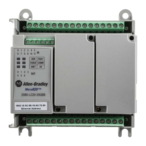
Micro820 20-Point Programmable Controllers Overview The Micro820 20-point controller is an economical brick style controller with embedded inputs and outputs. It can accommodate up to two plug-in modules, any 24V DC output power supply that meets minimum specifications such as the optional Micro800 power supply, 2080-PS120-240VAC. -
Page 8: Status Indicators
Micro820 20-Point Programmable Controllers Status Indicators Controller status LED indicators are located at the leftmost side of the controller, next to the two plug-in slots. Status Indicators Input status Fault status Run status Force status Communication status ENET status SD status... - Page 9 Micro820 20-Point Programmable Controllers Mounting Dimensions and DIN Rail Mounting 104 (4.09) 75 (2.95) 90 (3.54) 46253 Mounting dimensions do not include mounting feet or DIN rail latches. Measurements are in millimeters (inches). Module Spacing Maintain spacing from objects such as enclosure walls, wireways and adjacent equipment. Allow 50.8 mm (2.0 in.) of space on all sides for adequate ventilation.
- Page 10 Micro820 20-Point Programmable Controllers 2. Push the DIN rail latch back into the latched position. To remove your controller from the DIN rail, pry the DIN rail latch downwards until it is in the unlatched position. Panel Mounting The preferred mounting method is to use four M4 (#8) screws per module. Hole spacing tolerance: ±0.4 mm (0.016 in.).
- Page 11 Micro820 20-Point Programmable Controllers Install the microSD Card The Micro820 controller has a card slot for a microSD card. The microSD card is primarily used for project backup and restore. It is also used for data-logging and recipe and to change controller mode under specific conditions.
- Page 12 You also reduce the effects of voltage transients and electrical noise from radiating into adjacent systems. Refer to the Micro820 Programmable Controllers User Manual, publication 2080-UM005, for suitable surge suppression methods and recommended surge suppressors.
-
Page 13: Wire The Controller
Micro820 20-Point Programmable Controllers Grounding Your Analog Cable Use shielded communication cable (Belden #8761). The Belden cable has two signal wires (black and clear), one drain wire, and a foil shield. The drain wire and foil shield must be grounded at one end of the cable. - Page 14 Micro820 20-Point Programmable Controllers 2080-LC20-20AWB / 2080-LC20-20AWBR / 2080-LC20-20QWB / 2080-LC20-20QWBR Input Terminal Block +DC10 I-00 I-02 COM0 I-05 I-07 I-09 I-11 -DC24 I-01 I-03 I-04 I-08 I-10 I-06 +DC24 -DC24 O-00 O-01 O-02 O-05 -DC24 VO-0 O-03 O-04 O-06...
-
Page 15: Specifications
Micro820 20-Point Programmable Controllers Specifications General Specifications Attribute 2080-LC20-20AWB(R) 2080-LC20-20QBB(R) 2080-LC20-20QWB(R) Number of I/O 12 inputs, 8 outputs Dimensions 90 x 104 x 75 mm HxWxD (3.54 x 4.09 x 2.95 in.) Shipping weight, 0.38 kg (0.83 lb) approx. Wire size... - Page 16 Micro820 20-Point Programmable Controllers General Specifications Attribute 2080-LC20-20AWB(R) 2080-LC20-20QBB(R) 2080-LC20-20QWB(R) Output circuit type Relay 24V DC source Relay (standard and high-speed) Power input 24V DC Power consumption 5.62 W (without plug-ins, max)…8.5 W (with plug-ins, max) Power dissipation Power supply 20.4…26.4 V DC, Class 2, or...
- Page 17 Micro820 20-Point Programmable Controllers Analog Input Specifications for I-00…I-03 Attribute Value Number of inputs Type Voltage (single-ended) Data range 0...4095 Input voltage range 0…10V DC Maximum input 26.4V DC Input impedance 14.14 kΩ Resolution 12-bit, 2.5 mV/count Smoothing None Input time constant, typical 0.44 ms...
- Page 18 Micro820 20-Point Programmable Controllers DC Input Specifications Attribute Non-isolated, shared with Isolated inputs analog inputs (Inputs 00…03) (Inputs 04…11) – for 2080-LC20-20QWB(R), 2080-LC20-20QBB(R) only Voltage category 24V DC Sink 24V DC Sink/Source On-state voltage, nom 12/24V DC 24V DC On-state voltage range 9.8…26.4V DC...
- Page 19 Micro820 20-Point Programmable Controllers Relay Contact Ratings Maximum Amperes Amperes Volt-Amperes Volts Continuous Make Break Make Break 120 V AC 15 A 1.5 A 1800 240 V AC 7.5 A 0.75 A 24 V DC 1.0 A 125 V DC 0.22 A...
- Page 20 High speed output operation is greater than 5 Khz. PWM Output Duty Cycle Error Turn On/Off time for the Micro820 controllers for the PWM output port is 0.2 µs and 2.5 µs max, respectively. Duty cycle error is: Positive error = 2.5 µs * F Negative error = -0.2 µs * F...
- Page 21 Micro820 20-Point Programmable Controllers Auxiliary Power Supply for Thermistor Applications Attribute Value Output voltage 9.5V, min 10.04V, typical 10.5V, max Output current 10 mA, typical 50 mA, max Embedded RTC Attribute Value Resolution 1 sec Accuracy ± 52 sec/month @ 25 °C ±...
- Page 22 Micro820 20-Point Programmable Controllers Environmental Specifications Attribute Value Radiated RF immunity IEC 61000-4-3: 10V/m with 1 kHz sine-wave 80% AM from 80…2000 MHz 10V/m with 200 Hz 50% Pulse 100% AM @ 900 MHz 10V/m with 200 Hz 50% Pulse 100% AM @ 1890 MHz 10V/m with 1 kHz sine-wave 80% AM from 2000…2700 MHz...
- Page 23 Micro820 20-Point Programmable Controllers Notes: Publication 2080-IN009B-EN-P - April 2014...
- Page 24 Please contact your local Rockwell Automation representative for the return procedure. Allen-Bradley, Rockwell Automation, Micro800, Micro820, and TechConnect are trademarks of Rockwell Automation, Inc. Trademarks not belonging to Rockwell Automation are property of their respective companies. Publication 2080-IN009B-EN-P - April 2014 Supersedes Publication 2080-IN009A-EN-P - December 2013 Copyright ©...
Need help?
Do you have a question about the Micro820 and is the answer not in the manual?
Questions and answers