Table of Contents
Advertisement
Advertisement
Table of Contents

Related Manuals for AEA CIA-HF


Summary of Contents for AEA CIA-HF
-
Page 1: Operating Manual
CIA-HF Complex Impedance Analyzer Operating Manual... - Page 2 AEA Wireless, Inc. All rights reserved. Part Number 5012-3000 Rev. X 5/98 ©1998 by AEA Wireless, Inc. All rights reserved. This document and all software or firmware designed by AEA Wireless, Inc., is copyrighted and may not be copied or altered in any way without written consent from AEA Wireless, Inc.
-
Page 3: Table Of Contents
TABLE OF CONTENTS SECTION 1: INTRODUCTION What It Does…………………………………………………………………… Features………………………………………………………………………… ……………………………………………………….. Specifications SECTION 2: QUICK START………………………………………………… SECTION 3: OPERATION…………………………………………………… Set-Up………………………………………………………………………….. Screens………………………………………………………………………… Dedicated Keys……………………………………………………………….. Function Keys…………………………………………………………………. Frequency Sweep Range……………………………………………………. Resetting the Instrument…………………………………………………….. Automatic Off………………………………………………………………….. SECTION 4: APPLICATIONS……………………………………………… Tuning Simple Antennas……………………………………………………. Tuning ½ and ¼ Transmission Lines and Stubs…………………………. Measuring Inductors and Capacitors………………………………………. -
Page 4: Section 1: Introduction
SECTION 1. INTRODUCTION WHAT IT DOES The CIA-HF Complex Impedance Analyzer combines a microprocessor-controlled direct digital synthesizer with an accurate low-power Impedance bridge to present a graphical display of SWR, Impedance, Resistance, or Reactance. To create these graphical displays, the Analyzer continuously sweeps and plots a user-selectable frequency range. -
Page 5: Specifications
SPECIFICATIONS Frequency Range………………... 0.4 to 54 MHz Frequency Resolution…………… Increments of 1 kHz Frequency Accuracy…………….. ± ζΗ 002 Display Width…………………….. 0 to 10 MHz Harmonics and Spurious………… <-30 dB SWR Impedance…………………. 50 ohms SWR Range………………………. 1:1 to 20:1 Impedance Magnitude Ranges…. 0 to 100, 0 to 250, 0 to 1000 ohms Reactance Ranges………………. -
Page 6: Section 2: Quick Start
SECTION 2. QUICK START To help you get started, we’ve included this brief tutorial, which leads you through the general functions of the Analyzer. First, press the ON key to activate the Analyzer. An introductory screen will flash briefly on the display, followed by a simple SWR plot. -
Page 7: Section 3: Operation
SECTION 3. OPERATION SETUP Attach the load under test to the antenna connector, which is located on the top of the Analyzer. Press the ON key to activate the unit. CAUTION: Do not connect any transmitting equipment directly to the antenna connector. Excessive RF at the antenna connector will damage the Analyzer. -
Page 8: Dedicated Keys
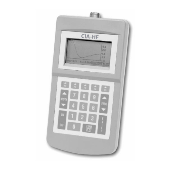
The five real time graphing screens include: SWR screen, Magnitude of Impedance screen, Reactance screen, Resistance screen, and Vector screen. These screens contain a graphing area, Data Box, and Logo Box (Figure1). The graphing area is 100 pixels wide. It is bordered on the right by a vertical axis containing a user-selectable scale, and on the bottom by a horizontal axis containing tick marks every ten pixels. -
Page 9: Function Keys
“LO BAT” massage will appear – refer to the Internal Access section for battery replacement information. Finally, if any problems are detected during the self-diagnostics, a “FAILURE” message will appear. In this case, call AEA’s technical support department for troubleshooting assistance (refer to In Case of Trouble section). - Page 10 When the cursor is aligned with the KEYS option, press ENTER to display a new screen listing the function definitions of the number keys and softkeys. Press ENTER a third time to return to the main user Menu screen. When the cursor is aligned with the CONTRAST option, use the FREQp and FREQq to adjust the display contrast level.
-
Page 11: Frequency Sweep Range
FL:xxx BW2.0: FH:xxx Lower Frequency @ SWR 2:1, Higher Frequency @ SWR 2:1 FL:xxx BW3.0: FH:xxx Lower Frequency @ SWR 3:1, Higher Frequency @ SWR 3:1 FL:xxx BW1.5: FH:xxx Lower Frequency @ SWR 1.5:1, Higher Frequency @ SWR 1.5:1 MIN SWR:xxx at F:xxx Lowest SWR, Frequency at which MIN SWR appears NORMALIZED Z:xxx 50-ohm Normalized value of Z expressed as real ±j... -
Page 12: Resetting The Instrument
RESETTING THE INSTRUMENT In the expert mode, the current screen and plot settings (i.e. center frequency, frequency step size, scale value, and width) are saved when you turn off the Analyzer. This feature allows you to power backup to the same screen and settings. To reset the Analyzer to its factory default settings, press any of the number keys to enter the Numerical Entry screen. -
Page 13: Section 4: Applications
SECTION 4. APPLICATIONS The following examples by no means describe the extent of the Analyzer’s capabilities, but are intended as jumping off points. To follow along with the examples, first activate the Analyzer’s expert mode (refer to Function Keys section). TUNING SIMPLE ANTENNAS Example: Tuning an 80-meter inverted “V”... -
Page 14: Tuning ½ And ¼ Transmission Lines And Stubs
TUNING ½ AND ¼ TRANSMISSION LINES AND STUBS Example: Using a standard Wilkenson power divider to stack two 15-meter yagi antennas with two ¾ wave sections of RG-11, 75-ohm coax lines. The ¾ wavelength cable is used in this example because two ¼ wavelength cables would not be long enough to allow optimum stacking distance between the two antennas. -
Page 15: Measuring Inductors And Capacitors
4. Begin cutting inch-long pieces off of the unterminated end of the phasing line. The resonant frequency of the SWR curve will increase as the line is shortened. 5. As the SWR dip descends lower in the plot, shorten the cuts to ¼ inch long. This allows you to finely tune the line. -
Page 16: Tuning Antenna Traps
Inductors Example: Determining the Inductance of a relatively small coil. Process: 1. Plug the 50-ohm accessory connector into the Analyzer and clip the coil between the two test leads. 2. Turn the Analyzer on and use the F5 softkey to scroll to the X screen. Enter 2 5 0 0 0 ENTER to select an initial center frequency of 25 MHz. -
Page 17: Determining Resonant Frequency
DETERMINING RESONANT FREQUENCY Example: Using the 50-ohm accessory connector constructed for the above example to determine the resonant frequency of an LC-tuned circuit. Process: 1. Use the test leads of the 50-ohm accessory connector to connect the inductor and capacitor in series. -
Page 18: Adjusting Antenna Tuners
ADJUSTING ANTENNA TUNERS Example: Adjusting an antenna tuner without transmitting a signal on the air. Process: 1. Connect a cable from the input of your antenna tuner to the center connector of a two- position coax switch (be sure to use a switch that shorts the unused portion). 2. -
Page 19: Measuring Cable Loss
OTHER APPLICATIONS Uses for the CIA-HF Analyzer are limited only by your imagination and experience. We encourage you to explore all of the Analyzer’s capabilities – those listed here and those wanting to be discovered. For more information on Antenna Impedance Matching, consult the ARRL... -
Page 20: Remote Operation
You have the option to assemble a cable yourself or purchase one of the serial interface cables, displayed below, directly from AEA. The Analyzer can be powered up manually, using the ON key, or remotely, using your PC. To remotely power up the Analyzer, simply send the letter “K”... - Page 21 Set the WIDTH to the following values x = 0 width set to 0 kHz per data point x = 1 width set to 1 kHz per data point x = 2 width set to 2 kHz per data point x = 3 width set to 5 kHz per data point x = 4 width set to 10 kHz per data point x = 5 width set to 20 kHz per data point...
- Page 22 F12345K ; Command sent to Analyzer: set center frequency to 12.345 MHz F12345K ; Response from Analyzer: center frequency set to 12.345 MHz B00K ; Command to Analyzer: report width and center frequency … 464, ; Response: data point #96 ( @ 12.6 MHz) SWR = 4.64 477, ;...
- Page 23 B02K ; Command to Analyzer: report frequency Z, R, X, and Angle ; Response from Analyzer: 501,501,0,-0K ; Response: Z = 50.1, R = 50.1, X = 0, Angle = -0° B05K ; Command to Analyzer: report frequency low, high for 2:1 bandwidth ;...
-
Page 25: Section 5: Glossary
SECTION 5. GLOSSARY Capacitive Reactance – The Reactance of a circuit resulting from Capacitance, or the property of a device or component that enables it to store energy in an electrostatic field and release it later. Center Frequency – The frequency corresponding to the center of a plot; defines the midpoint of the frequency sweep range. -
Page 26: Section 6: Internal Access
X: Real time sweep display of a test load’s Reactance vs. frequency curve. V: Real time sweep display of a test load’s Impedance (Resistance vs. Reactance) vector for a selected center frequency. D: Consolidates a number of the data blocks displayed in the Data Box; these data blocks are displayed and updated in real time. -
Page 27: Section 7: Limited Warranty
All units returned to the factory, delivery charges prepaid, and deemed defective under this warranty, will be replaced or repaired at this company’s option. No other warranties are implied, nor will responsibility for operation of this instrument be assumed by AEA Wireless, Inc.
Need help?
Do you have a question about the CIA-HF and is the answer not in the manual?
Questions and answers