Makita DTD148 Technical Product Information
Hide thumbs
Also See for DTD148:
- Instruction manual (37 pages) ,
- Instructions manual (84 pages) ,
- Instruction manual (69 pages)
Advertisement
Quick Links
Download this manual
See also:
Instruction Manual
T
ECHNICAL INFORMATION
Model No.
Description
C
ONCEPT AND MAIN APPLICATIONS
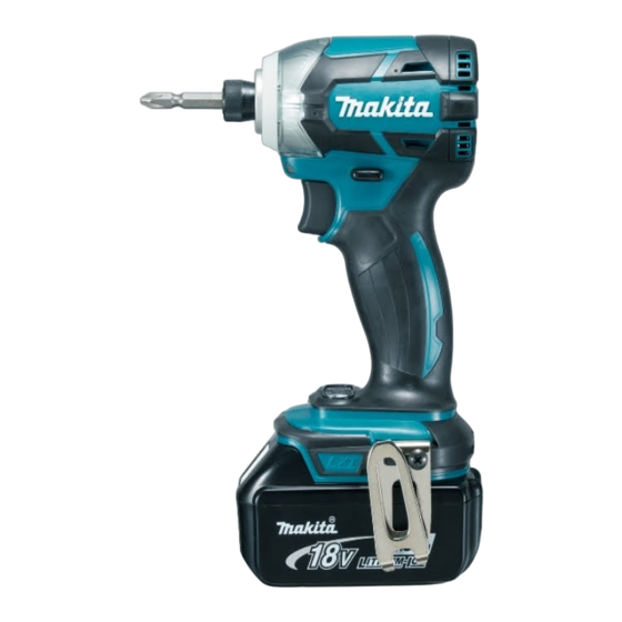
Model DTD148 Cordless Impact Driver is an advanced version
of the current model DTD147.
It features more compact body (overall length: 119mm) and
higher power than DTD147 while having the following same
benefits as the current model:
• Brushless motor
• Electronic 3-stage impact power selection
with variable power control in each range
• XPT (eXtreme Protection Technology) for use in outdoor
applications or harsh environments
• T-mode (Tightening mode for self-drilling screw)
This product is compatible with 18V- 1.3Ah, 1.5Ah, 2.0Ah, 3.0Ah, 4.0Ah or
5.0Ah Li-ion batteries
BL1815, BL1815N, BL1820, BL1830, BL1840 or BL1850.
S
pecification
Voltage: V
Capacity: Ah
Battery
Energy capacity: Wh
Cell
Charging time (approx.): min.
Max output (W)
Driving shank
Machine screw
Standard bolt
Capacities
High tensile bolt
Coarse-thread
Impact power selection
Impacts per min.: min.
No load speed: min.
¹=rpm
ˉ
Max. tightening torque
Electric brake
Variable speed control by trigger
Reverse switch
LED job light
Weight according to EPTA-Procedure 01/2003: kg (lbs)
*3 Tightening torque at 3 seconds after seating, when tightening M16 (grade 10.9) high strength bolt.
*4 With Battery BL1815, BL1815N or BL1820
*5 With Battery BL1830, BL1840 or BL1850
S
tandard equipment
Belt clip
Battery
, Battery cover
*6
Charger
, Plastic carrying case
*6
O
ptional accessories
Phillips bits
Socket bits
Drill chucks
Drill bits with 6.35mm Hex shank
Hole saws for impact driver
Bit piece
Stopper for impact driver
Hook set (Belt clip)
DTD148
Cordless Impact Driver
¹=ipm
Hard/ Medium/ Soft
ˉ
Hard/ Medium/ Soft
: N.m [kgf.cm] (in.lbs)
*3
*6 Battery and charger are not supplied with "Z" model
*7
*7 Supplied with the same quantity of extra Battery
Note: The standard equipment may vary by country or model variation.
Tool catcher set
Battery protectors
Li-ion Battery BL1850
Li-ion Battery BL1840
Li-ion Battery BL1830
Li-ion Battery BL1820
Li-ion Battery BL1815N
Li-ion Battery BL1815
PI / SC / NP
海外営業管理承認
18V
1.3, 1.5, 2.0, 3.0, 4.0, 5.0
24, 27, 36, 54, 72, 90
Li-ion
15, 15, 24, 22, 36, 45 with DC18RC
290
6.35mm (1/4") Hex
M4 - M8 (5/32 - 5/16")
M5 - M16 (3/16 - 5/8")
M5 - M14 (3/16 - 9/16")
22 - 125mm (7/8 - 4-7/8")
Electronic 3 stage (Hard/ Medium/ Soft)
+ Teks screw mode
0 - 3,800/ 2,600/ 1,100
0 - 3,600/ 2,100/ 1,100
175 [1,780] (1,550)
Yes
Yes
Yes
Yes
1.2 (2.8)
/ 1.5 (3.3)
*4
Charger DC18SD
Charger DC24SC
Fast charger DC18RC
Automotive charger DC18SE
Four port multi charger DC18SF
OFFICIAL USE
for ASC & Sales Shop
PRODUCT
P 1/ 14
L
H
W
Dimensions: mm (")
Length (L) 119 (4-11/16)
Width (W)
79 (3-1/8)
220 (8-5/8)*
Height (H)
238 (9-3/8)*
*1 With Battery BL1815, BL1815N
or BL1820
*2 With Battery BL1830, BL1840
or BL1850
*5
1
2
Advertisement

Related Manuals for Makita DTD148


Summary of Contents for Makita DTD148
- Page 1 Description Cordless Impact Driver ONCEPT AND MAIN APPLICATIONS Model DTD148 Cordless Impact Driver is an advanced version of the current model DTD147. It features more compact body (overall length: 119mm) and higher power than DTD147 while having the following same benefits as the current model: •...
- Page 2 Disassembling/assembling Hammer case 134848-9 Socket 32-50 Disassembling/assembling Hammer case [2] LUBRICATION Apply Makita grease FA. No.2 to the following portions designated with the black triangle to protect parts and product from unusual abrasion. Item No. Description Portion to lubricate Amount...
- Page 3 P 3/ 14 epair [3] DISASSEMBLY/ASSEMBLY [3] -1. Hammer case complete DISASSEMBLING (1) Pull out Hammer case section from Rotor shaft as drawn in Fig. 2. Fig. 2 1. Remove Bumper with a thin slotted Remove Hammer case cover from Hammer case complete screwdriver.
- Page 4 P 4/ 14 epair [3] DISASSEMBLY/ASSEMBLY [3] -1. Hammer case complete (cont.) DISASSEMBLING (2) Disassemble Hammer case section. (Fig. 3) Fig. 3 2. Fit Socket 30-78 (134847-1) to 3. Turn 1R223 clockwise. Hammer case complete the hexagonal portion of Hammer 1R223 case complete.
- Page 5 P 5/ 14 epair [3] DISASSEMBLY/ASSEMBLY [3] -1. Hammer case complete (cont.) ASSEMBLING (1) Assemble Hammer case section. (Figs. 4, 5, 6 and 7 ) (2) Mount Hammer case section to Housing in the reverse order of disassembly. (Fig. 2) (3) Assemble Bumper to the machine.
- Page 6 P 6/ 14 epair [3] DISASSEMBLY/ASSEMBLY [3] -2. Rotor DISASSEMBLING (1) Remove Bumper and Hammer case cover. Then, after removing Housing (R), separate Motor section from Hammer case section. (Fig. 2) (2) Rotor can give damage on the coil of Stator complete when pulling it off from Stator complete because Rotor attracts Stator complete with its very strong magnetic force.
- Page 7 P 7/ 14 epair [3] DISASSEMBLY/ASSEMBLY [3] -2. Rotor (cont.) ASSEMBLING (1) Assemble Rotor as drawn in Fig. 12 Fig. 12 1. Holding Stator complete on 2. When the drive end of Rotor workbench, slowly insert Rotor reaches workbench, lift up in Stator complete until Rotor’s Stator complete slowly.
- Page 8 P 8/ 14 epair [3] DISASSEMBLY/ASSEMBLY [3]-2. Bit Holder Section and Anvil DISASSEMBLING (1) Disassemble Hammer case section from the machine as drawn in Fig. 2. (2) Disassemble Bearing box from Hammer case complete, then take out Internal gear 51 and Hammering mechanism as drawn in Fig.
- Page 9 P 9/ 14 epair [3] DISASSEMBLY/ASSEMBLY [3] -4. Mounting Hammer case section, Motor section and Switch to Housing (L) ASSEMBLING (1) Assemble Stator unit and Hammer case complete to Housing set L as drawn in Fig. 17. Fig. 17 Fit two depressions of Stator unit to two projections of Housing set L, and fit the projection of Hammer case complete to the depression of Housing set L.
- Page 10 P 10/ 14 epair [3] DISASSEMBLY/ASSEMBLY [3]-5. Hammer section DISASSEMBLING (1) Disassemble Hammer case section from the machine as drawn in Fig. 2. (2) Disassemble Bearing box from Hammer case complete, then take out Internal gear 51 and Hammering mechanism as drawn in Fig.
- Page 11 P 11/ 14 ircuit diagram Fig. D-1 Color index of lead wires' sheath Purple Black Blue Gray White Orange Yellow LED circuit Stator Switch Connector Connector Controller This Lead wire is This Lead wire is red for some countries, instead of white. Fuse Heat shrink tube Terminal...
- Page 12 P 12/ 14 iring diagram Fig. D-2 Wiring in Housing set L Section A Caution 1: Be careful not to pinch Lead wires of LED light circuit between Stopper of Hammer Stopper of Hammer case complete and Housing set. case complete After assembling Hammer case to Housing set L, set the Lead wires of LED light circuit in place.
- Page 13 P 13/ 14 rouble shooting Whenever you find any trouble in your machine, first, refer to this list to check the machine for solution. Note in Repairing Fig. D-3 (1) Use the full charged battery which has the star mark. (Fig. D-3) Star mark (2) When Housing is disassembled, check the conditions of the electrical parts (Connectors, Lead wires, Switches, etc.), Armature, Stator unit, Gear section, etc.
- Page 14 P 14/ 14 rouble shooting Test for recognizing the trouble on FET (Field effect transistor) in Controller mark on the tester: Refer to Fig. D-4.) Set Digital tester (1R402) in the diode mode ( Do the following steps. Test 1: Attach Black tester bar to the plus pole of Terminal. Attach Red tester bar to one of UVW terminal connected with Red, White, Blue lead wires.
Need help?
Do you have a question about the DTD148 and is the answer not in the manual?
Questions and answers