
Subscribe to Our Youtube Channel
Summary of Contents for Reflex iC60N
- Page 1 Reflex iC60 Integrated Control Circuit Breaker A9MA03EN 02/2012 Reflex iC60 Integrated Control Circuit Breaker iC60 Circuit-Breakers Reference Manual 02/2012 www.schneider-electric.com...
-
Page 2: A9Ma03En
The information provided in this documentation contains general descriptions and/or technical character- istics of the performance of the products contained herein. This documentation is not intended as a substitute for and is not to be used for determining suitability or reliability of these products for specific user applications. -
Page 3: Table Of Contents
Selection of the Operating Mode..........Automatic Overheat Protection for the Reflex iC60 Integrated Control Circuit Breaker .. - Page 4 A9MA03EN 02/2012...
-
Page 5: Safety Information
Safety Information § Important Information NOTICE Read these instructions carefully, and look at the equipment to become familiar with the device before trying to install, operate, or maintain it. The following special messages may appear throughout this documentation or on the equipment to warn of potential hazards or to call attention to information that clarifies or simplifies a procedure. - Page 6 A9MA03EN 02/2012...
-
Page 7: About The Book
This manual is intended for designers and installers of control systems and electrical protection systems. Validity Note Reflex iC60 integrated control circuit breakers are used for remote control and protection of installations via either electrical control or PLC control. Related Documents... - Page 8 A9MA03EN 02/2012...
-
Page 9: Chapter 1 Introduction
Reflex iC60 Integrated Control Circuit Breaker Introduction A9MA03EN 02/2012 Introduction What’s in this Chapter? This chapter contains the following topics: Topic Page Overview Description A9MA03EN 02/2012... -
Page 10: Overview
The Reflex iC60 integrated control circuit breaker combines the function for remote control of an installation and the protection functions of a circuit breaker in a single unit. Reflex iC60 integrated control circuit breakers are available with 2, 3 and 4 poles. - Page 11 A9C65340 A9C66340 A9C64440 A9C65440 A9C66440 Description of optional auxiliaries The iMDU adapter auxiliary enables the Reflex iC60 integrated control circuit breaker to be used with a 24 to 48 V AC/DC control voltage. Product designation Catalog number Description iMDU A9C18185 24 or 48 V AC/DC –...
-
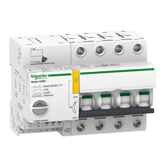
Page 12: Description
Introduction Description Reflex iC60 integrated control circuit breaker without Ti24 interface A9C5pppp Mode 1 Mode 2 Reflex iC60N Ready-Mode1.2.3 I. ON O. OFF Overheat auto Local control auto/ 230 V AC power supply terminal block Y1/Y2 control input terminal block... -
Page 13: Chapter 2 Installation
Reflex iC60 Integrated Control Circuit Breaker Installation A9MA03EN 02/2012 Installation What’s in this Chapter? This chapter contains the following topics: Topic Page Assembly Connection A9MA03EN 02/2012... -
Page 14: Assembly
Pull out the padlocking device Check that the handle is in OFF position (circuit breaker open) Remove the blanking plate on the right-hand side of the Reflex iC60 circuit breaker using a screwdriver Assemble the Vigi iC60 auxiliary with the Reflex iC60 circuit breaker... - Page 15 Pull out the padlocking device Check that the handle is in OFF position (circuit breaker open) Remove the blanking plate on the right-hand side of the Reflex iC60 circuit breaker using a screwdriver Assemble the Vigi iC60 auxiliary with the Reflex iC60 circuit breaker...
-
Page 16: Connection
This equipment must be installed inside a suitable electrical cabinet. Failure to follow these instructions will result in death or serious injury. Connection Blocks The following diagram shows the 6 connection blocks of a Reflex iC60 integrated control circuit breaker with Ti24 interface. Reflex iC60N Ready-Mode1.2.3... - Page 17 Installation The following diagram shows the 5 connection blocks of a Reflex iC60 integrated control circuit breaker without Ti24 interface. Reflex iC60N Ready-Mode1.2.3 I. ON O. OFF Overheat auto Local control auto/ 230 V AC power supply terminal block Y1/Y2 control input terminal block...
- Page 18 RISK OF MALFUNCTION In three-phase applications, use the same phase to connect the power supply and inputs Y1 and Y2. Keep to the recommended minimum power for the Reflex iC60 integrated control circuit breaker power supply. Failure to follow these instructions can result in equipment damage.
- Page 19 Y1 Y2 auto/OFF 21 22 24 11 12 14 The following diagram illustrates connection of a Reflex iC60 integrated control circuit breaker, with Ti24 interface, used in mode 1, 2 or 3: 24 V c 24 V auto/OFF O/C 0V...
- Page 20 Supplying the Control Inputs Using an iMDU Auxiliary The Y1/Y2 control inputs on Reflex iC60 integrated control circuit breakers operate at 230 V AC voltage. An iMDU auxiliary is used to control a Reflex iC60 integrated control circuit breaker via a 24/48 V AC/DC output.
-
Page 21: Chapter 3 Use
Reflex iC60 Integrated Control Circuit Breaker A9MA03EN 02/2012 What’s in this Chapter? This chapter contains the following topics: Topic Page Operating Modes Selection of the Operating Mode Automatic Overheat Protection for the Reflex iC60 Integrated Control Circuit Breaker Operation A9MA03EN 02/2012... -
Page 22: Operating Modes
(Y1 and Y2). In addition, the version with Ti24 interface has an additional control input (Y3) dedicated to control from a PLC. The Reflex iC60 version without Ti24 interface has 2 operating modes: mode 1 and mode 2. Mode 1 is the default mode. - Page 23 Operation is as follows: When input Y1 or input Y3 (Ti24) changes to 1, the Reflex iC60 circuit breaker switches to closed position When input Y1 or input Y3 (Ti24) changes to 0, the Reflex iC60 circuit breaker switches to Ready...
- Page 24 Y1 the Reflex iC60 circuit breaker switches to closed position Input Y2 is inhibited when input Y1 is at 1 If input Y1 is at 0, a pulse on input Y2 (rising edge) makes the Reflex iC60 circuit breaker switch alternately from Ready position (contacts open) to closed position...
- Page 25 The behavior of the control inputs is specific to each connection diagram. Connection diagram 1 The following connection diagram is based on a selector (input Y1) so that the Reflex iC60 circuit breaker uses, in exclusive mode, the controls: On input Y2 (in this case, controls on input Y3 are ineffective)
- Page 26 When input Y1 is at 1, input Y2 is ineffective (local control) and input Y3 (centralized control via Ti24) is operational A pulse on input Y2 makes the Reflex iC60 circuit breaker switch alternately from Ready position (contacts open) to closed position...
- Page 27 Ready position (contacts open) to closed position The state of input Y3 is taken into account on rising edge of Y1: If input Y3 is at 1 when there is a rising edge on Y1 the Reflex iC60 circuit breaker switches to closed position.
-
Page 28: Selection Of The Operating Mode
Selection of the Operating Mode Checking the Operating Mode To check the operating mode of the Reflex iC60 circuit breaker, the handle must be in the upper position (auto). The LED indicates the operating mode: Mode 1: the LED flashes once green... - Page 29 Selection of the Operating Mode The circuit breaker’s operating mode is selected using the manual control pushbutton on the circuit breaker. The following procedure describes the actions to be performed to select the operating mode of the Reflex iC60 circuit breaker. u 2 s e1 .2...
- Page 30 Action Pull out the padlocking device to set the handle on the circuit breaker to OFF position. Press the pushbutton on the Reflex iC60 circuit breaker for at least 3 seconds so that the LED flashes alternately green and orange.
-
Page 31: Automatic Overheat Protection For The Reflex Ic60 Integrated Control Circuit Breaker
Automatic Overheat Protection for the Reflex iC60 Integrated Control Circuit Breaker Description If the Reflex iC60 integrated control circuit breaker receives too many control orders in too short a time period, overheat protection is automatically activated (Overheat) to limit the device’s potential temperature rise and maintain its service life. -
Page 32: Operation
Operation Local Indication (LED) State of the LED indicator on the Reflex iC60 integrated control circuit breaker with and without Ti24 interface: LED (item H) Circuit breaker status The integrated control circuit breaker is ready. It is possible to control the closing of the contactor by means of Y1, Y2, Y3 and the pushbutton on the front of the Reflex iC60 circuit breaker. - Page 33 NOTE: (Filtering) The O/C and auto/OFF contacts may change state for less than 10 ms. These brief changes of state (bounce) must not be taken into account and must be filtered by a device external to the Reflex iC60 circuit breaker.
- Page 34 Step Action Pull out the padlocking device from the Reflex iC60 integrated control circuit breaker Attach the padlock (diameter 3 to 6 mm) to the padlocking device On 3P/4P circuit breaker models attach a second padlock to the circuit breaker using the A9A26970...
-
Page 35: Chapter 4 Application Examples
Reflex iC60 Integrated Control Circuit Breaker Application examples A9MA03EN 02/2012 Application examples What’s in this Chapter? This chapter contains the following topics: Topic Page Outdoor parking lot lighting Office lighting Workshop lighting A9MA03EN 02/2012... -
Page 36: Outdoor Parking Lot Lighting
Manually using pushbuttons The proposed solution is as follows: The 2 banks of lights are controlled by 2 Reflex iC60 circuit breakers without Ti24 interface (A9C5••••) set to mode 1. A multifunction time switch combined with a light sensitive switch sends opening or closing commands to each circuit breaker via input Y1 according to the time slots corresponding to the periods when the parking lot is used. -
Page 37: Office Lighting
The proposed solution is as follows: The office lighting is controlled by Reflex iC60 circuit breakers without Ti24 interface (A9C5••••) set to mode 2. In this mode, when Y1 is at high state, the circuit breaker is open and the controls on input Y2 are inhibited. -
Page 38: Workshop Lighting
The proposed solution is as follows: 2 banks of lights in the workshop are controlled by Reflex iC60 circuit breakers connected to a PLC via the Ti24 interface and set to mode 3. In this mode, input Y1 is used to choose between local mode (Y1 = 0) and centralized mode (Y1 = 1). - Page 39 Application examples iC60N Supervisory control system PLC: Twido 24 V c Power supply Inputs Outputs ABL8 230 VAC/ 24 VDC 24 V 24 V c auto/ 24 V Y3 auto/ 24 V Y3 Ti24 Ti24 Reflex Reflex iC60 iC60 Mode 3...
- Page 40 Application examples A9MA03EN 02/2012...
-
Page 41: Chapter 5 Technical Characteristics
Reflex iC60 Integrated Control Circuit Breaker Technical Characteristics A9MA03EN 02/2012 Technical Characteristics General characteristics Characteristics Value Degree of protection (IEC 60529) Device alone IP20 Device in a modular enclosure IP40 (insulation class II) Degree of protection (IEC 62262:2002) IK05 Degree of pollution (IEC 60947) - Page 42 100 mA DC according to IEC 61 131-2 Length of control wires for input Y3 at 24 V DC/AC 500 m Dimensions The dimensions of the Reflex iC60 integrated control circuit breaker, optionally assembled with a Vigi iC60 are as follows: X + 72 X + 54...
- Page 44 A9MA03EN-01 A9MA03EN-01 Schneider Electric Industries SAS As standards, specifications and designs change from time to time, please ask for confirmation of the information given in this publication. 35, rue Joseph Monier CS30323 F - 92506 Rueil Malmaison Cedex 02/2012 www.schneider-electric.com...
Need help?
Do you have a question about the iC60N and is the answer not in the manual?
Questions and answers