
Related Manuals for Tim Sistem RITTIUM 6


Summary of Contents for Tim Sistem RITTIUM 6
- Page 1 RITTIUM 6 pellet stove RITTIUM 7 pellet stove Owners’s manual INSTALATION, ADJUSTMENT AND OPERATING INSTRUCTION RITTIUM 6 RITTIUM 7 EN 14785:2006...
-
Page 2: Table Of Contents
CONTENT .....10 6. CONTROL UNIT..............................6.1. USING OF CONTROL UNIT ..........................10 7. OPERATING THE STOVE ............................12 7.1 STARTING THE STOVE ............................12 7.2 INITIAL PELLET LOADING (LOAD PELLET) AND STARTING FIRE ............12 7.3 STARTING FIRE ..............................13 7.4 OPERATION MODE .............................. - Page 3 1. ABOUT PELLET Pellet is an energy fuel with high energy efficiency that is produced in special technological process of milling, drying and pressing of various materials of biological origin. As raw materials for its production can be used wood from forestry waste, firewood, sawdust and other wood waste (wood pellets); the straw of wheat and soybeans, corn and sunflower husks (agro pellets).
- Page 4 • Keep the children or pets away from the stove, because some parts emit high temperatures and they can cause burns; • do not touch the parts that emit a high temperature, such as smoke drain, glass, fire door, the side; •...
- Page 5 3. TECHNICAL CHARACTERISTICS Technical characteristics are presented in following table: Power 6 kW 8 kW 10 kW Dimensions RITTIUM 6 (Wx D x H) 457 x 570 x 1016 Dimensions RITTIUM 7 (W x D x H) 457 x 570 x 1006...
- Page 6 RITTIUM 6 1. Air inlet Ø50mm 2.Exhaust Ø80mm RITTIUM 7 1.Air inlet Ø50mm 2.Exhaust Ø80mm Picture 1. Dimensions...
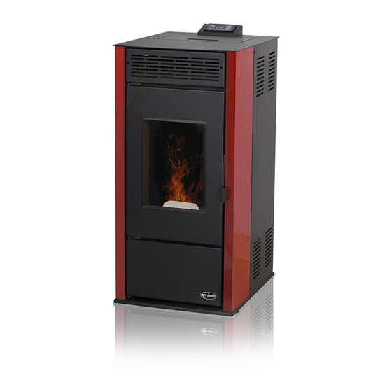
- Page 7 4. BASIC FEATURES OF THE STOVE Picture 2. Basic features. 1. Top plate 10. Control unit and display 2. Fire box doors 11. Storage cover 3. Door glass 12. Zadnja strana 4. Door handle 13. Exhaust 5. Vrata pepeljare 14. Primary air inlet 6.
- Page 8 5. INSTALATION OF THE STOVE With a stove you get the user manual, remote control, power cable. Parts that are included with the stove are presented on Picture 3. Picture 3. Before you start installation of the stove, you must read carefully instructions for use and maintenance get to know well a regional regulations and legislation, in order to apply them.
- Page 9 All appliances, which discharge combustion to the exterior, must have a proper flue. The same flue must never be used for more than one appliance. The tubes, which connect the stove to the flue, must be carefully sealed together, especially at the connection point between the stove and/or cooker and the flue.
-
Page 10: Control Unit
6. CONTROL UNIT 6.1. USING OF CONTROL UNIT Led indicator of Led indicator of Led ON/OFF room temerature thermal output P1 P2 button P3 P1 button Display P3 button Led programing, apperance Led alarm, Led alarm, Led convection fan, Led lighter Picture 6. - Page 11 Display shows informations related Status, Power and Parameters. Following table shows current status and display content: STATUS DISPLAY CONTENT OFF + room temperature ON (ACC) ON + room temperature LOADING Pellet loading OPERATING STOVE Room temperature + Power + Time STOVE PROGRAMING Selected parameter REMOTE CONTROL...
-
Page 12: Operating The Stove
7. OPERATING THE STOVE This chapter describes the way the sotve is functioning since moment of start until it is turned off, programing included 7.1 STARTING THE STOVE Before starting the stove, display will show „OFF“. In order to start the stove press P3 for several seconds. -
Page 13: Starting Fire
7.3 STARTING FIRE When temperature of gases in firebox achieves temperature set by parameters, system is entering Starting fire mode. Display shows FLAME LIGHT and led indicator “ON/OF” blinks. Picture 10. Display appearance: „FLAME LIGHT“ In this phase, temperature should remain stabile for period which is already set by parameters. 7.4 OPERATION MODE Stove is entering Operation mode after the temperature of exhaust gasess achieve value which is bigger than temperature set by parameters. -
Page 14: Thermal Output Setting
7.5 THERMAL OUTPUT SETTING During operating stove, it is possible to tune Thermal output by pressing P2 (led indicator of thermal power is ON). To increase thermal output, press P2 again. To decrease, press P1. Demanded thermal output will be presented on display (picture 13). To exit settings, don’t use control panel for 5 seconds or press P3. -
Page 15: Stand - By Mode
7.8 STAND - BY MODE STAND BY option should be primarily activated in the Menu. It enables the stove to turn OFF when all set points are reached or surpassed for aprox. 2 minutes. Also, if room temperature is overpassing the set point for more than 2ºC, this mode starts in several minutes. -
Page 16: Turning Off The Stove
7.9 TURNING OFF THE STOVE To turn OFF the stove, press P3 and wait for display to show „CLEANING FINAL”. Auger will turn OFF but convection fan and exhaust fan will continue to work. Led indicator ON/OFF will blink as shown on picture 19. Picture 19. - Page 17 M2 PROGRAMING M21 – Programing active 01 - Programing active On / off M2-2 – daily programing 01 day setting On / off 02 start 1 day Off 0-23:50 02 stop 1 day Off 0-23:50 02 start 2 day Off 0-23:50 02 stop 2 day Off 0-23:50 M2-3 –...
-
Page 18: Time Setting
01 italian 02 english 03 french 04 german/spanish STAND BY 01 stand by On / off SOUND ALERT 01 sound alert On / off INITIAL LOADING 01 initial loading 90" М7 status stove 01 status stove 01-Status auger Info 02-T minutes Iinfo 03-Status thermostat Info... -
Page 19: Menu M2-1 Programing The Stove
Picture 23. Picture 24. Picture 25. Picture 26. Picture 27. 8.3 MENU M2-1 PROGRAMING THE STOVE SUB MENU M1-2- Activation of stove programing Menu „M2 set hrono“enables you to activate all functions of time programing. To activate this menu, press P3. By pressing P1 and P2 turn the picked option ON or OFF. Confirm with P3 (Picture 28). - Page 20 Picture 28. SUB MENU M2-2- Daily program Pick the M2-2 – daily program with pressing P3 to get different options of daily programing. Picture 29. You can set up two working groups, the first with START STOP1 Day 1 and the second with START2 Day and STOP2 Day, delimited by the times set according to the following table.
-
Page 21: Menu M3 - Language
M2-3-03 Stop Prg 1 Deactivation period OFF-0-23:50 M2-3-04 Monday Prg 1 0n/off M2-3-05 Tuesday Prg 1 0n/off M2-3-06 Wednesday Prg 1 0n/off M2-3-07 Thursday Prg 1 0n/off M2-3-08 Friday Prg 1 0n/off M2-3-09 Saturday Prg 1 0n/off M2-3-10 Sanday Prg 1 0n/off Above mentioned options of the MENU with their explanations are same in case of Program 2, 3 and 4 (starting with M2-3-11 up to M2-3-37). -
Page 22: Menu M5- Sound Alert
(Picture 31). Picture 31. 8.6 MENU M5- SOUND ALERT This Menu enables activating of Sound alert in case of malfunction. Turning on and off is regulated with buttons P1 i P2. Press P3 to confirm. Picture 32. 8.7 MENU M6- INITIAL PELLET LOADING This option is available only when stove is turned OFF. -
Page 23: Menu M7- Current Status
8.8 MENU M7- CURRENT STATUS After entering menu M7, by pressing P3, Display will show certain variables of the current status. Example of visual presentation is listed below. Status Explanation 3,1" Auger mode durin uploading pellet 52΄ Time out T off Status of of thermostat ͦ... - Page 24 Alarm is turning on after time period which is set by Parameter PR11 (exept alarm for no electricity) and it can be reset with pressing P3. Each time alarm turn on for safety reasons, stove will shut down. In case that sound alert option is activated, sound alert will turn on. Even in case that Alarm is not noticed and stopped by customer, stove will stop working and display will present information related kind if malfunction.
- Page 25 In case that pressure probe indicates lower pressure than it is needed to ignite the stove, presostat will stop the auger. Alarm led indicator is ON same as Alarm and display shows„Al8 alar al 8 “. Stove will shut down. 10.
- Page 26 Picture 36. Schedule of disassembling because of monthly cleaning...
- Page 27 The warranty is valid from the date of purchase, as evidenced by duly completed guarantee certificate, and the shop’s receipt. The warranty for this product is 24 months. TIM SISTEM is obliged to provide spare parts in due time after the stove is no longer produced. This warranty does not cover damage caused by: •...
- Page 28 TIM SISTEM d.o.o. Prva industrijska 9 22 330 Nova Pazova, Serbia tel/fax: +381 22 32 80 76 e-mail: office@timsistem.rs www.timsistem.rs...
Need help?
Do you have a question about the RITTIUM 6 and is the answer not in the manual?
Questions and answers