User' s Guide
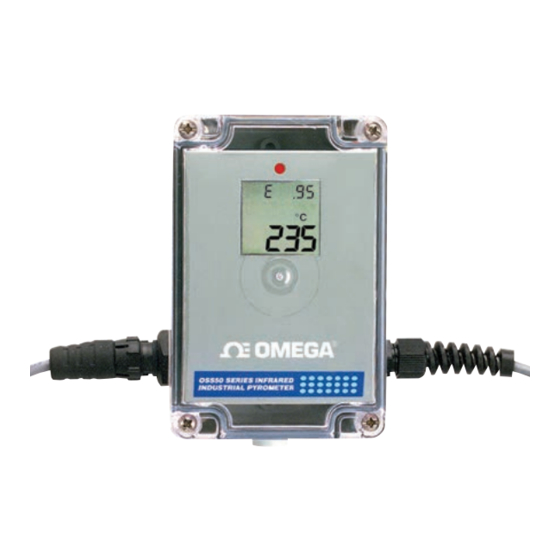
STANDARD PLASTIC CASE - OS550A
Shop online at
omega.com
®
e-mail: info@omega.com
or latest product manuals:
omegamanual.info
ALUMINUM CASE - OS550AM
(OPTIONAL)
OS550 /OS550 M/
OS550 -BB Series
Industrial Infrared
Thermometer/Transmitter


Need help?
Do you have a question about the OS550A and is the answer not in the manual?
Questions and answers