Table of Contents
Advertisement
Advertisement
Table of Contents

Subscribe to Our Youtube Channel
Related Manuals for Omega OMEGASCOPE OS520


Summary of Contents for Omega OMEGASCOPE OS520
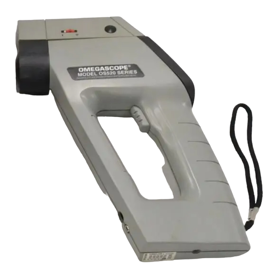
- Page 1 User’ s Guide omega.com ® OMEGA ® http://www.omega.com e-mail: info@omega.com ISO 9001 ISO9002 CERTIFIED CERTIFIED CORPORATE QUALITY CORPORATE QUALITY STAMFORD, CT MANCHESTER, UK Shown with Built-in Laser Sighting OS520, OS520E, OS521, OS522, OS523, OS524 OMEGASCOPE ® Handheld Infrared Thermometer...
- Page 2 Toll Free in England: 0800-488-488 e-mail: info@omega.co.uk It is the policy of OMEGA to comply with all worldwide safety and EMC/EMI regulations that apply. OMEGA is constantly pursuing certification of its products to the European New Approach Directives. OMEGA will add the CE mark to every appropriate device upon certification.
-
Page 3: Unpacking Instructions
Unpacking Instructions Remove the Packing List and verify that you have received all equipment, including the following (quantities in parentheses): OS520 Series Handheld Infrared Thermometer (1) AA Size Lithium Batteries (4) Soft Cover Carrying Case (1) Analog Cable (1) RS-232 Cable (only for OS521 through OS524) (1) 3.5”... - Page 4 Unpacking Instructions This page is intentionally blank...
-
Page 5: Table Of Contents
OS520 Series TABLE OF CONTENTS Handheld Infrared Thermometer Page Unpacking Instructions Chapter 1 General Description Introduction Parts of the Thermometer 1.2.1 Front of the Thermometer 1.2.2 Rear of the Thermometer Chapter 2 Using the Handheld Infrared Thermometer How to Power the Thermometer 2.1.1 Battery Operation 2.1.2 ac Power Operation Operating the Thermometer... - Page 6 OS520 Series TABLE OF CONTENTS Handheld Infrared Thermometer Page Chapter 5 Maintenance Replacing the Batteries Cleaning the Lens Cleaning the Power Contacts Calibrating the Thermometer Servicing the Laser Sight Module Chapter 6 Troubleshooting Guide Chapter 7 Specifications .............. 7-1 Chapter 8 Glossary of Key Strokes ..........8-1 Appendix A How Infrared Thermometry Works ......
- Page 7 TABLE OF CONTENTS...
-
Page 8: Chapter 1 General Description
General Description 1.1 Introduction The OS520 series Handheld Infrared (IR) Thermometers provide non-contact temperature measurements up to 4500°F. They offer effective solutions for many non-contact temperature applications, including the following: • Predictive Maintenance: Tracking temperature shifts which indicate pending failure in solenoid valves. •... - Page 9 General Description The thermometer is easy to use: • Units have standard “V” groove aiming sights. • Integral tripod mount permits hands-free operation, if necessary. • Temperature readings are switchable from °F to °C via the keypad. • Parameters, such as target material emissivity and alarm setpoints, can be set and remain in memory until reset.
-
Page 10: Parts Of The Thermometer
General Description 1.2 Parts of the Thermometer 1.2.1 Front of the Thermometer Laser Sight Power Contacts covered by a "V" Groove protective label IR lens Rubber Boot °F Backlit LCD (Dual Display) Membrane Switch (4 keys) Display Trigger Rubber Boot Battery Compartment Door... - Page 11 General Description HAL LOBAT °F °C LAL PRN Figure 1-2. Display and Keypad View Table 1-2. Display Details Description ➀ Display Mode displays one of the following: E (Emissivity) HAL (High Alarm Setpoint) MAX (Maximum Temperature) LAL (Low Alarm Setpoint-only on OS521 to 524) MIN (Minimum Temperature) AMB (Ambient Target Temp-only on OS521 to 524) dIF (Differential Temperature)
-
Page 12: Rear Of The Thermometer
General Description 1.2.2 Rear of the Thermometer Figure 1-3 shows the various jacks that are used to connect a recorder, a computer, and/or the ac adapter to the thermometer. The figure also shows the location of the tripod thread mount used for fixed point monitoring. - Page 13 General Description Notes...
-
Page 14: Chapter 2 Using The Handheld Infrared Thermometer
Using the Handheld Infrared Thermometer 2.1 How to Power the Thermometer 2.1.1 Battery Operation Invert the thermometer and install 4 fresh AA size batteries as shown in Figure 2-1. Make sure the batteries’ polarities are correct, the batteries are not put in backwards, and are of the same type. NOTE If the icon flashes, the batteries must be... -
Page 15: Operating The Thermometer
Using the Handheld Infrared Thermometer 2.2 Operating the Thermometer (Without the Laser Sight Module) -Aim the thermometer at the target to be measured. Use the “V” groove (shown in Figure 1-1) on top of the thermometer to align the target to the thermometer’s field of view. - Page 16 Using the Handheld Infrared Thermometer Figure 2-4. Field of View OS520 & OS520E DISTANCE: SENSOR TO OBJECT (FT) 20" 4.8" 4.2" 3.6" 1.0" @ 0" to 20" 3.0" 2.4" 1.8" 1.0" 1.2" 1.0" D:S = 20:1 2.5cm @ 51cm 10.0 *SPOT DIAMETER MEASURED 12.2 AT 90% ENERGY...
- Page 17 Using the Handheld Infrared Thermometer Figure 2-6. Field of View OS522 & OS523-1 ** Measurement distance is from the outside surface of the rubber boot. DISTANCE: SENSOR TO OBJECT (FT) 0.9"@ 0 9" 5.4" 1.8" 0.9" 110:1 22mm @ 0 *SPOT DIAMETER MEASURED AT 90% ENERGY DISTANCE: SENSOR TO OBJECT (M)
- Page 18 Using the Handheld Infrared Thermometer DISTANCE: SENSOR TO OBJECT (FT) 2.9" 1.9" 0.9"@ 0 1.2" 1.0" 0.9" 60:1 22mm @ 0 *SPOT DIAMETER MEASURED AT 90% ENERGY DISTANCE: SENSOR TO OBJECT (M) Figure 2-8. Field of View OS523-2 DISTANCE: SENSOR TO OBJECT (FT) 3’...
- Page 19 Using the Handheld Infrared Thermometer 3. The target temperature and emissivity are displayed on the LCD. Determine the emissivity of the target (refer to Appendix B). Press the key to increment the target emissivity. Press the key to decrement the target emissivity. 4.
-
Page 20: Measurement Techniques
Using the Handheld Infrared Thermometer 2.2.1 Measurement Techniques You can use the IR Thermometer to collect temperature data in any one of five different ways: • Spot Measurement — Measures the temperature of discrete objects such as motor bearings, engine exhaust manifolds, etc.: Aim at the desired target and pull the trigger. - Page 21 Using the Handheld Infrared Thermometer NOTE Center hole is the analog output jack Analog Cable To Strip Chart Recorder Figure 2-10. Recorder Hookup After all the data has been taken, press the key to unlock the trigger. • Moving Surface Scan - Measures the Temperature of Points on a Moving Surface: Mount the thermometer on a camera tripod and aim at a fixed point on the moving surface.
-
Page 22: Real Time Mode (Active Operation)
Using the Handheld Infrared Thermometer 2.3 Real Time Mode (Active Operation) Definition: Real Time Mode is the active operational mode of the thermometer. In this mode, the thermometer constantly measures and displays temperature. Start Pull Trigger Sleep Mode Display turns off Immediately (Release Press... - Page 23 Real Time Mode Display Display shows: Press to... Press to... Press to... Mode: Current temperature Set emissivity Go to Emissivity Current temperature Go to Maximum temperature LOCK or UNLOCK Press to change Current temperature trigger Go to between °F/°C Minimum temperature Current temperature Go to Differential temperature...
- Page 24 Using the Handheld Infrared Thermometer MODE DISPLAY DISPLAY MODE °F °F °F °F °F °F (Model OS521) °F °F °F (Model OS522) (Model OS522, OS523, OS524) °F (Model OS520 & OS520E) Figure 2-12. Visual Function Flow Chart While in these 4 modes: key to change temperature from °F to °C or vice versa.
-
Page 25: Adjusting Emissivity
Using the Handheld Infrared Thermometer 2.3.1 Adjusting Emissivity Refer to Appendices B and C for information on emissivity. 1. Determine the emissivity of the target. °F 2. Aim at the target and pull the trigger. 3. If necessary, press the key to increment the target emissivity or press the key to decrement the target... -
Page 26: Calculating Temperature Values
Using the Handheld Infrared Thermometer 2.3.3 Calculating Temperature Values The thermometer calculates the MAX, MIN, dIF, and AVG temperatures based on the current temperature. °F °F °F is the maximum temperature is the difference between is the minimum since the temperature the MAX and MIN temperature since the measurement session starts... -
Page 27: Using The Alarm Functions
Using the Handheld Infrared Thermometer 2.3.6 Using the Alarm Functions The thermometer provides audible and visible alarm indications. • To set the high alarm value: Pull the trigger. Then press and hold the key until °F the High Alarm Display Mode (HAL) appears. Press the key to increment the high alarm value. - Page 28 Using the Handheld Infrared Thermometer • To set the low alarm value (OS521 through OS524): Pull the trigger. Then press and hold the key until the Low Alarm Display Mode (LAL) appears. °F Press the key to increment the low alarm value. Press key to decrement the low alarm value.
-
Page 29: Using Ambient Target Temperature Compensation (Os521 Through Os524)
Using the Handheld Infrared Thermometer 2.3.7 Using Ambient Target Temperature Compensation (OS521 through OS524) Use the Ambient Target Temperature Compensation (AMB) Display Mode when high accuracy readings under °F both of these conditions are required: • The target has a low emissivity. •... -
Page 30: Sending Temperature Data To A Serial Printer (Os521 Through Os524)
Using the Handheld Infrared Thermometer Press and hold the key until the Emissivity Display °F Mode (E) appears. Change the emissivity to the proper value for the target being measured (refer to Section 2.3.1). Aim at the target. The target temperature and emissivity are displayed on the LCD. - Page 31 Using the Handheld Infrared Thermometer °F NOTE Bottom hole is the RS-232 jack Serial Printer RS-232 Digital Cable 25-pin 'D' 6-pin Connector Phone Jack To the To the Printer Thermometer Figure 2-13. Serial Printer Hookup Pull the trigger and press the key to lock the trigger.
-
Page 32: Sending Temperature Data To A Personal Computer (Os521 Through Os524)
Using the Handheld Infrared Thermometer After all data is taken, press the key again and °F icon disappears. Press and hold the key until the Emissivity Display Mode (E) appears. Press the key to unlock the trigger. 2.3.9 Sending Temperature Data to a Personal Computer (OS521 through OS524) The thermometer can transmit temperature data to a Personal Computer via the RS-232 phone jack and the... - Page 33 Using the Handheld Infrared Thermometer Press and hold the key until the Print Data Display °F Mode (PRN) appears. Press the key to increment the printing interval. Press key to decrement the printing interval. The printing interval (from 1 to 1999 seconds) is the time between data points.
- Page 34 Using the Handheld Infrared Thermometer The following is a typical data that appears on the screen. °F 002 S 0.84 TEMP TIME 00:00:00 00:01:00 Figure 2-16. Computer Screen Showing Typical Data Press the key on the thermometer to stop transmission of temperature data to the Personal Computer.
-
Page 35: Storing The Temperature Data On Command (Os522 Through Os524)
Using the Handheld Infrared Thermometer 2.3.10 Storing the Temperature Data on Command (OS522 through OS524) The thermometer can store up to 100 temperature data points on command. Each set of temperature data is broken °F down into the temperature value, emissivity, and high alarm setpoint for that temperature. -
Page 36: Erasing The Temperature Data From Memory
Using the Handheld Infrared Thermometer 2.3.11 Erasing the Temperature Data from Memory The user can erase all 100 temperature data points in memory at any time by using the following procedure: Pull the trigger and press the key. The icon will appear. -
Page 37: Recall Mode (Passive Operation)
Using the Handheld Infrared Thermometer 2.4 Recall Mode (Passive Operation) Definition: Recall Mode is the passive operational mode of the thermometer. In this mode, you may review the most recently stored temperature data and parameters. Start Pull Trigger Sleep Mode Display Turns off immediately (Release... - Page 38 Recall Mode DISPLAY Display shows: Press to... Press to... Press to... MODE: Last temperature Go to Emissivity Last temperature Go to Maximum temperature Last temperature Go to Minimum temperature Last temperature Go to Differential temperature Disabled Last temperature Disabled Go to Average temperature Last temperature Go to...
-
Page 39: Reviewing The Last Parameters
Using the Handheld Infrared Thermometer 2.4.1 Reviewing the Last Parameters The thermometer stores the last temperature measured in the real time mode (refer to Table 2-1). This temperature °F can be recalled by pressing the key. - Press the key to review the most recently stored temperature data and parameters. - Page 40 Using the Handheld Infrared Thermometer Run the communications program IRP.EXE that is °F provided on the 3.5” floppy disk on your Personal Computer. This procedure is also described in Step 6 of Section 2.3.9. Press and hold the key until you see the Print Display Mode (PRN) appear.
-
Page 41: Reviewing Previously Stored Temperature Data (Os522 Through Os524)
Using the Handheld Infrared Thermometer 2.4.3 Reviewing Previously Stored Temperature Data (OS522 through OS524) You can review all 100 stored temperature values on the thermometer display using the following procedure: °F Press and hold the key until you see the Memory Display Mode (MEM) appear. -
Page 42: Chapter 3 Laser Sight Module
Laser Sight Module 3.1 Warnings and Cautions CAUTION You may receive harmful laser radiation exposure if you do not adhere to the warnings listed below: • USE OF CONTROLS OR ADJUSTMENTS OR PERFORMANCE OF PROCEDURES OTHER THAN THOSE SPECIFIED HERE MAY RESULT IN HAZARDOUS RADIATION EXPOSURE. -
Page 43: Description
Laser Sight Module 3.2 Description The Laser Sight Module is an accessory for the thermometer. It provides a visual indication of the field of view of the thermometer. Aiming at distant targets (up to 75 feet) becomes much easier by using the Laser Sight Module. -
Page 44: Operating The Laser Sight Module
Laser Sight Module 3.3 Operating the Laser Sight Module Make sure the power contacts on the thermometer and the Laser Sight Module are clean. Refer to Section 4.3. 3.3.1 Installing the Laser Sight Module onto the Thermometer NOTE When assembling the Laser Sight Module on top of the thermometer, the thermometer should be off. - Page 45 Laser Sight Module Laser Dot Laser Circle Figure 3-5. Two Laser Configurations The visibility of the laser beam depends on the ambient light levels. NOTE The Laser Sight Module turns on only when used with the thermometer. The module does not turn on by itself. Since the Laser Sight Module mounts on top of the thermometer, the line of sight of the thermometer does not coincide with that of the Laser Sight Module, as shown in Figure 3-6.
-
Page 46: Removing The Laser Sight Module From The Thermometer
Laser Sight Module 3.3.2 Removing the Laser Sight Module from the Thermometer NOTE When disassembling the Laser Sight Module from the thermometer, the thermometer and the Laser Sight Module should both be off. 1. Turn off the thermometer and the Laser Sight Module. 2. -
Page 47: Chapter 4 Sighting Scope
Sighting Scope 4.1 Sighting Scope The Sighting scope is an accessory for the thermometer. It provides a visual indication of the target being measured. Aiming at distant targets (up to 200 feet) becomes much easier by using the Sighting scope. 4.2 Installing and Operating the Sighting Scope 1. - Page 48 Laser Sight Module Line of sight of Pair of Mounting Clamps the sighting scope 1 11/16 (42.8 mm) Line of sight of the thermometer Figure 4-1. Installing the Sighting Scope...
- Page 49 Sighting Scope Notes...
-
Page 50: Chapter 5 Maintenance
Maintenance 5.1 Replacing the Batteries NOTE When you change the batteries, all of the set parameters (i.e. emissivity, high alarm, low alarm, Target Ambient Temperature) will be reset to the default values. For your convenience, you may want to write down all of the set parameters BEFORE replacing the batteries. -
Page 51: Cleaning The Lens
Maintenance 5.2 Cleaning the Lens Although all lenses are quite durable, take care to prevent scratching when cleaning them. To clean the lens: 1. Blow off loose particles, using clean air. 2. Gently brush off remaining particles, using a camel hair brush. Alternatively, clean any remaining contaminants with a damp, soft, clean cloth. -
Page 52: Chapter 6 Troubleshooting Guide
Troubleshooting Guide THERMOMETER Problem Solution The thermometer does 1a. Properly install fresh batteries. not turn on (No Display) 1b. If operating under ac power, check that the ac adapter is plugged in properly to the ac wall outlet and to the thermometer. - Page 53 Troubleshooting Guide Problem Solution The thermometer is Remove and reinstall the batteries or “locked up” (the disconnect and reconnect the ac display is “frozen”). adapter. The display is either Clean the thermometer lens. erratic or stays at one Refer to Section 4.2. reading.
- Page 54 Troubleshooting Guide Problem Solution If you see an error code, either “ERR1”, “ERR2”, or “ERR3”, record the code and call our Customer Service Department. Provide Customer Service with the error code that is displayed in the upper left corner of the display. The Customer Service Department representative may ask you to return the thermometer to the...
- Page 55 Troubleshooting Guide Problem Solution The thermometer resets The trigger is pulled two times in itself unexpectedly. rapid sequence. Wait at least 2 The emissivity has been seconds between two successive reset to .95. All other trigger pulls. You may need to set parameters are reset to the emissivity, low alarm, high the default values.
- Page 56 Troubleshooting Guide LASER SIGHT MODULE Problem Solution No Laser Beam 1. Make sure the power contacts on the top of the thermometer are clean. 2. Correctly install the Laser Sight Module. Refer to Chapter 3. 3. Make sure the trigger is pulled and the laser power switch is pressed.
- Page 57 Troubleshooting Guide Notes...
-
Page 58: Chapter 7 Specifications
Specifications (Specifications are for all models except where noted) THERMOMETER Measuring: OS520: 0°F to 750°F (–18°C to 400°C) Temperature OS520E: 0°F to 1000°F (–18°C to 538°C) Range: OS521: 0°F to 1000°F (–18°C to 538°C) OS522: 0°F to 1600°F (–18°C to 871°C) OS523: 0°F to 2500°F (–18°C to 1371°C) OS524:... - Page 59 Specifications Calculated Temperature Maximum (MAX), Minimum (MIN), Values: Average (AVG), Differential (dIF) Ambient Target Temperature Compensation: OS521: set and enabled via keypad OS522, OS523, OS524 RS232 Output (for OS521 thru 524: standard personal computers and serial printers): 4800 bits per second, 8 bits of data, 1 stop bit, no parity RS-232 Cable: RJ12 to 25 pin D connector, Female...
- Page 60 Specifications ac adapter: Optional - available in 120 Vac or 220Vac Class 2 Transformer, UL & CSA Listed (Input voltage): 120Vac or 220Vac at 60 or 50 Hz (Output voltage): 9Vdc at 200 mA (Output plug [female]): Center positive, coax 2.5/5.5/12mm –...
- Page 61 Specifications Max. Output Optical Power: <5mW at 75°F ambient temperature, Class IIIa Laser Product Safety Classification: Class 3A Maximum Operating Current: 50mA at 5.5 V FDA Classification: Complies with 21 CFR Chapter 1, Subchapter J Beam Diameter: 5 mm Beam Divergence: <1mrad Operating Temperature: 32°F to 122°F (0°C to 50°C)
-
Page 62: Chapter 8 Glossary Of Key Strokes
Glossary of Key Strokes Key(s) Key(s) Functions • Selects one of the following Display Modes: E , MAX, MIN, dIF, AVG, HAL, LAL, AMB, PRN, or MEM. • Locks/unlocks the trigger. • Enables/disables High and Low Alarms. • Enables/disables Target Ambient Temperature Compensation. - Page 63 Glossary of Key Strokes Notes...
-
Page 64: Appendix A How Infrared Thermometry Works
Appendix: How Infrared Thermometry Works Thermal Radiation Heat is transferred from all objects via radiation in the form of electromagnetic waves or by conduction or convection. All objects having a temperature greater than absolute zero (-459°F, -273°C, 0 K) radiate energy. The thermal energy radiated by an object increases as the object gets hotter. - Page 65 Appendix: How Infrared Thermometry Works Blackbody When thermal radiation falls on an object, part of the energy is transmitted through the object, part is reflected and part is absorbed. A blackbody is defined as an ideal object that absorbs all the radiation incident upon it.
- Page 66 Appendix: How Infrared Thermometry Works Wien’s Displacement Law describes the exact mathematical relationship between the temperature of a blackbody and the wavelength of the maximum intensity radiation. 2.898 λ where = wavelength measured in microns T = temperature in Kelvin Calculating Temperature The net thermal power radiated by an object has been shown to depend on its emissivity, its temperature and that of the ambient...
- Page 67 Appendix: How Infrared Thermometry Works Optics Field of View Accurate measurement of temperature via infrared means depends strongly on the size of the object and the distance between the thermometer and the object. All optical devices (e.g. cameras, microscopes, infrared thermometers) have an angle of vision, known as a field of view or FOV, within which they see all objects.
- Page 68 Appendix: Emissivity Values Table B-1 provides guidelines for estimating the emissivity of various common materials. Actual emissivity, especially of metals, can vary greatly depending upon surface finish, oxidation, or the presence of contaminants. Also, emissivity or infrared radiation for some materials varies with wavelength and temperature.
- Page 69 Appendix: Emissivity Values Material Emissivity ( ) Asbestos Board ......... . 0.96 Asphalt, tar, pitch .
-
Page 70: Appendix C Determining An Unknown Emissivity
Appendix: Determining an Unknown Emissivity In Appendix A, we showed how emissivity is an important parameter in calculating the temperature of an object via infrared means. In this section we discuss how to determine a specific emissivity value. If you know the material of the object, use Table B-1 in Appendix B to look up its approximate emissivity. - Page 71 Appendix: Determining an Unknown Emissivity Method 3 Use this method to measure objects at temperatures below 500°F (260°C). Place a large piece of masking tape on the object (or at least a sample of the object material). Allow time for the masking tape to reach the object temperature.
- Page 72 Appendix - Determining an Unknown Emissivity Method 4 Paint a sample of the object material with flat black lacquer paint. Set the emissivity to 0.97 and measure and record the temperature of the painted portion of the sample material - Area ‘A’ in Figure C-1.
- Page 73 Appendix: Determining an Unknown Emissivity Notes...
- Page 74 Index ac Adapter Input Jack ..... 1-5 Diagnostic Program ....5-2 Active Operation ...... 2-7 Differential Measurement ..2-5 Aiming Sight “V Groove” ..1-3 Display Alarms ......2-12, 2-13 Icons: ATC ......1-4 Alkaline Batteries ..2-1, 4-1, 6-3 Backlighting ..
- Page 75 Index Field of View: Keypad, 4-position ....1-3 Diagrams ....... 2-3 Keys: Positions ........ 2-2 M & °F-°C ....... 1-3, 1-4 Fixed Point Monitoring over FUNC (Function) ..1-3, 1-4 Time Measurement ....2-6 LOCK (Lock) ....1-3, 1-4 L & ❍-G......1-3, 1-4 Key Strokes .......
- Page 76 Index Main Display ......1-4 Serial Printer Hookup ... 2-15 Modes: Sleep Mode ...... 2-7, 2-22 Real Time ......2-7 Spectral Distribution ....A-2 Recall ......... 2-22 Spot Measurement ....2-5 Moving Surface Scan ....2-6 Static Surface Scan ....2-5 Stefan-Boltzmann Law ...
-
Page 77: Index
Index Notes... - Page 78 Where Do I Find Everything I Need for Process Measurement and Control? OMEGA…Of Course! TEMPERATURE Thermocouple, RTD & Thermistor Probes, Connectors, Panels & Assemblies Wire: Thermocouple, RTD & Thermistor Calibrators & Ice Point References Recorders, Controllers & Process Monitors Infrared Pyrometers PRESSURE, STRAIN AND FORCE Transducers &...
- Page 79 Department will issue an Authorized Return (AR) number immediately upon phone or written request. Upon examination by OMEGA, if the unit is found to be defective it will be repaired or replaced at no charge. OMEGA’s WARRANTY does not apply to defects resulting from any action of the purchaser, including but not limited to mishandling, improper interfacing, operation outside of design limits, improper repair, or unautho- rized modification.
Need help?
Do you have a question about the OMEGASCOPE OS520 and is the answer not in the manual?
Questions and answers