
Related Manuals for KKT chillers vBoxX 8


Summary of Contents for KKT chillers vBoxX 8
- Page 1 Vario-Line Instruction Manual vBoxX 6 vBoxX 8 vBoxX 10 vBoxX 12 vBoxX 15 vBoxX 18 vBoxX 24 vBoxX 28...
- Page 2 Germany T +49 9228 9977 7190 * F +49 9228 9977 7474 E service@kkt-chillers.com W www.kkt-chillers.com Service USA KKT chillers, Inc. 1280 Landmeier Road Elk Grove Village IL 60007 T +1 847 734 1600 F +1 847 734 1601 TF +1 866 517 6867 E support@kkt-chillersusa.com...
-
Page 3: Introduction
It also contains advice on how to prevent or remedy faults. Allow yourself sufficient time to read through this manual carefully and to take in all the information it contains. If you have any further questions you can contact the KKT chillers service team; refer to the contact details. -
Page 4: Table Of Contents
Contents Introduction ............................. 3 Product description........................8 1.1. Intended use ........................8 1.2. Elements ...........................10 1.3. Explanation of the terms used ..................11 Function and main components .....................12 2.1. Compressor ........................12 2.2. Evaporator ........................13 2.3. Condenser ........................13 2.4. Expansion valve........................13 2.5. Refrigerant ........................13 2.6. - Page 5 3.17. Conductance monitoring ....................24 3.18. Conductance control ......................24 3.19. Special voltage .........................24 3.20. Phase monitoring ......................25 3.21. Output control < ±0.5K ....................25 3.22. UL version .........................25 3.23. Special paint finish ......................25 3.24. Air filter mat (accessory) ....................25 3.25. Vario Foot (accessory) ......................25 3.26.
- Page 6 Handling and Storage ......................38 5.1. Dangerous goods ......................38 5.2. Transport ..........................38 5.2.1. Fork-lift truck......................38 5.3. Unpacking .........................39 5.4. Storage ..........................39 Installation..........................40 6.1. Overview ...........................40 6.2. Installation site .........................40 6.2.1. General Information ....................40 6.2.2. Minimum volume ......................40 6.2.3. Ambient temperature ....................41 6.2.4.
- Page 7 8.7.4. Compressor control system ..................57 8.7.5. Fan speed control .....................57 8.7.6. Electronic expansion valve control ................57 8.7.7. Temperature limit monitoring ..................57 8.7.8. Group fault message ....................57 Cleaning ............................58 9.1. Air filter mat ........................58 9.2. Condenser ........................58 9.3. Water filter ........................58 9.4.
-
Page 8: Product Description
Please read through all the points of this instruction manual before starting up the machine. You should pay special attention to the sections on safety, starting up and operation. If you have any further questions about your machine, please contact the KKT chillers service team (see Table 1: Contact details) 1.1. - Page 9 Table 3: Technical specifications Vario-Line vBoxX 6 vBoxX 8 vBoxX 10 vBoxX 12 vBoxX 15 vBoxX 18 vBoxX 24 vBoxX 28 Refrigerating capacity @ tw2=20°C / tu=32°C 10.2 12.4 15.3 18.3 24.5 28.5 Refrigeration circuit hermetically tight Refrigerant R410A 2088...
-
Page 10: Elements
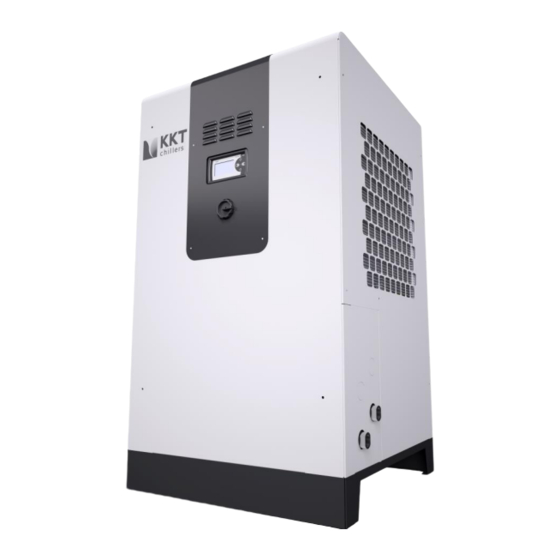
1.2. Elements Operating side Safety instructions Cover Water connections Service side tank Nameplate Service side compressor Display Condenser safety grille Main switch Tank filling 10 / 82 83000602.Ke... -
Page 11: Explanation Of The Terms Used
1.3. Explanation of the terms used For improved understanding, several important terms which are used frequently in this document are briefly explained here. Table 4: Explanation of the terms used Term Explanation Application The heat source connected hydraulically with the chiller. Process circuit Application and piping to the chiller. -
Page 12: Function And Main Components
2. Function and main components The chiller consists of the main components: compressor, condenser, expansion valve and evaporator, which are arranged in a circuit (Figure 1). Refrigerant circulates in this circuit. This absorbs heat from the cold water and discharges this to the ambient air drawn-in in the condenser. Heat Condenser and fan Expansion... -
Page 13: Evaporator
R410A is a fluorinated greenhouse gas consisting of the zeotropic mixture of 50% R32 and 50% R125 with virtually negligible glide. R410A has a very high volumetric refrigerating capacity and has no ozone depletion potential (ODP=0). A corresponding safety data sheet can be requested from our KKT chillers service team (see Table 1: Contact details). -
Page 14: Oil
The polyolestor oil FV50S is used for this. The oil is soluble in the refrigerant and distributes itself with the refrigerant in the whole refrigerating circuit. A corresponding safety data sheet can be requested from our KKT chillers service team (see Table 1: Contact details). -
Page 15: Pump
Figure 2: Opening the control cabinet 2.13. Pump The chiller's pump ensures the necessary circulation of the cold water. This is drawn out of the chiller's internal tank and is pumped through the process circuit. The units can also be supplied optionally as continuous flow coolers without tank, with pump or without tank and without pump (see Chapter 3.1 Version without tank, with pump... - Page 16 16 / 82 83000602.Ke...
-
Page 17: Materials Used In The Water Circuit
2.16. Materials used in the water circuit The basic fitout has the material composition shown in Table 5: Table 5: Materials used in the basic version Component Material Unit connections V2A 1.4305 Evaporator V2A 1.4301 and copper (99.9%) Tank V2A 1.4301 Tank connection sockets V4A 1.4305 Pump... -
Page 18: Water Quality
Furthermore, slime-forming bacteria must be prevented in the cooling water. If this is not possible, KKT chillers can recommend or provide an appropriate inhibitor to remove the slime forming agents on the basis of a biological water analysis carried out in advance. -
Page 19: Allowable Liquids
2.18. Allowable liquids Water and mixtures of water / Antifrogen N (AFN) or water / Antifrogen L (AFL) according to the details in Chapter 2.17 Water quality. The following table shows the requirements for the mix ration of water with antifreezes AFN and AFL. These values must be kept to as accurately as possible in order to maintain your machine's efficiency and prevent damage to components. -
Page 20: Options And Accessories
The items marked with "accessory" are enclosed with the unit and can also be ordered later at any time under the relevant product number. The installer of the machine is responsible for installation of the accessory. You can also ask our KKT chillers service team to carry out this installation (see Table 1: Contact details). -
Page 21: Control Cabinet Heating
The cooling water temperature is recorded by an additional temperature sensor in the cooling water inlet and is displayed at the controller display. The water quality listed under Table 7: Water quality must be complied with – the manufacturer does not accept any liability whatsoever for damage caused by a different water specification! The project-specific data and adapted PI flow chart and dimensioned diagram are given in the enclosed quick-start documentation. -
Page 22: Tank Heating With Thermostatic Pump Start
3.6. Tank heating with thermostatic pump start The tank heating is used to maintain a minimum temperature in the tank. The pump circulates the cold water while the tank heating controls the temperature in the system. We recommend a hydraulic installation as shown in Figure 4. -
Page 23: Higher Pressure Pump
3.8. Higher pressure pump The standard Vario-Line units are designed with a 3 bar pump, which is designed to the nominal flow rate of the respective unit. Optionally, the units can also be supplied with higher pressure pumps within the minimum or maximum flow rate limits. The pump characteristic of the pump(s) used in your unit is enclosed with the unit. -
Page 24: Automatic Water Feed
3.14. Automatic water feed Any leaks and evaporation during the course of the operation can reduce the required quantity of cold water available for the chiller function. The Automatic water feed option makes it possible to top up the cold water circuit automatically. The tank contents are monitored continuously and if necessary additional water is fed in until it has reached the optimum level once again. -
Page 25: Phase Monitoring
The filter is removed for cleaning and is washed out with water or a mild lye (alkaline solution). Highly soiled filters must be replaced by a new filter. Please contact the KKT chillers service team (Contact details). -
Page 26: Liquid Circuit Filter Assembly (Accessory)
3.27. Liquid circuit filter assembly (accessory) The water filter protects the chiller's cold water circuit from dirt. The set, consisting of a filter, fitting and two shut-off devices, is enclosed with the chiller in a separate package and is to be fitted in the cold water inlet of the chiller from the outside when the chiller is installed. -
Page 27: Sea Crate Packaging (Accessory)
3.33. Sea crate packaging (accessory) Seaworthy packaging of the Compact-Line is produced according to the phytosanitary regulations for international trade with packaging made of solid wood (International Standards for Phytosanitary Measures - ISPM 15). This means that the crate is made using heat-treated solid wood from which all bark has been removed. -
Page 28: Vboxx
Table 9: Definition of the safety symbols Note and follow the instructions for use! The machine must be safely disconnected from the power supply before it is opened! Then wait for at least 2 minutes before opening the machine. Warning! Electric shock! If the machine is only switched off at its main switch, dangerous electrical voltage is still applied at several terminals in the control cabinet. -
Page 29: Residual Energy
In particular, the following hazard warnings apply to the machine: Table 10: Hazard Warnings WARNING! Work on the chiller must be carried out by competent personnel! The surfaces of the pipes and components of the refrigerant and cold water circuit as well as the electrical equipment can be very hot during operation or for a while afterwards. -
Page 30: Safety Devices And Safeguards
Dangerous electrical voltage in the control cabinet despite switched off main switch o If the machine is switched off at its main switch only, dangerous electrical voltage is still applied at several terminals in the control cabinet. In particular, these include the main infeed terminal and the input terminals of the main switch. -
Page 31: Low Pressure Monitoring
4.4.3. Low pressure monitoring If the low pressure in the refrigerating circuit of your system is too low for the specified liquid there is a risk of frost. For this reason the low pressure is monitored continuously and the compressor is switched off if the pressure falls below a minimum value. -
Page 32: Airborne Sound Emission
Table 11: Personal protective equipment for service work Wear safety footwear! Wear protective gloves! Wear eye protection! Wear protective clothing! 4.6. Airborne sound emission The airborne sound emission is given as the sound pressure level, measured at a distance of five meters without reflection. -
Page 33: Notes On Reducing Noise And Vibration
4.7. Notes on reducing noise and vibration 4.7.1. Noise Chapter 4.6 contains details of the airborne sound emission of your chiller. In order to reduce the noise nuisance caused by airborne sound emissions it is advisable to install the chiller outdoors and out of the range of workplaces. If this is not possible we recommend that when installing the chiller you ensure that the air intake side is not directed directly towards a workplace or workstation. -
Page 34: Others
4.8.4. Others WARNING! Risk of suffocation if the chiller is installed in a room that is too small. Refer to Chapter 6.2.2. WARNING! In the EU you must follow the provisions of EN378-3. You must also comply with the local installation regulations and provisions, especially (in Germany) the VAwS and the BGR500 Chapter 2.35. -
Page 35: Oil
Measures in case of accidental release: Environmental protection methods: Where possible do not allow it to get into the environment. Cleaning methods: Leave the product to evaporate. Handling and storage: Handling: Fire and explosion protection: Heating results in a pressure increase and risk of bursting. -
Page 36: Reasonably Foreseeable Misuse
Further information: The effect of fire can cause the container to burst or explode. Ignitable gas-air mixtures possible under certain conditions. Measures in case of accidental release: Environmental protection methods: Do not allow it to get into the sewers or bodies of water. -
Page 37: Information For Emergencies
Parts of the machine have come undone mechanically. o The machine makes unusual noises. o The machine vibrates severely. Then contact the KKT chillers service team. If you have noticed that refrigerant or oil has escaped, proceed as described in Chapter 4.9 Hazardous substances. -
Page 38: Handling And Storage
5. Handling and Storage The chiller is delivered from the factory fixed onto a wooden pallet. Furthermore, the machine is protected from damage by polystyrene corners and stretch film. For this reason you should remove the packaging as late as possible. 5.1. -
Page 39: Unpacking
5.3. Unpacking WARNING! Packaging straps are mechanically tensioned and can recoil when cut. Risk of injuries! Remove carefully all tapes, films, protection corners and spacers. Optional accessories may also be located under the film. Ensure that these are also not damaged. The packaging can be recycled according to the local regulations. -
Page 40: Installation
6. Installation 6.1. Overview Several tasks must be completed to install the chiller. The following flow chart shows the order in which they are carried out: Prepare installation site Install the machine Flush the cold water circuit ... -
Page 41: Ambient Temperature
Table 13: Minimum volume of the installation room with regard to maximum refrigerant concentration in case of a leak if the chiller is installed indoors vBoxX [m³] Rmin refrigerant Rmin installation instructions 18.7 21.0 [m³] If the calculation of the minimum necessary room volume is related to the respective refrigerant fill quantity only, a room volume of 7 m³... -
Page 42: External Installations
Figure 10: Waste air duct by way of example For duct systems with a pressure loss greater than 5 Pa an external ventilation system with variable air quantity must be provided. Please contact our KKT chillers service team (see Table 1: Contact details). -
Page 43: Surface And Foundation
6.2.8. Surface and Foundation The surface on which the machine is installed must be flat and horizontal. All the machine's feet must have uniform contact with the floor or ground. Ensure that the floor/subsurface has sufficient load-bearing capacity. The installation instructions (Appendix II) recommend a continuous concrete foundation with the given minimum size. -
Page 44: Installation
6.2.12. Installation Filling and feeding Draining Unit outlet cold water circuit 1 (VL) Unit inlet cold water circuit 1 (RL) Unit outlet cold water circuit 2 (VL) Unit inlet cold water circuit 2 (RL) 6.2.13. Hydraulic installation The plant designer is responsible for choosing the material and cross-section of the hydraulic connections between the chiller and application. -
Page 45: Frost Protection Measures
6.2.14. Frost protection measures The chiller is exposed to a frost hazard by two different situations. Both an ambient temperature < 0°C and a flow temperature < 8°C entail the risk of freezing of system parts of the cold water circuit. Installation at ambient temperature <... -
Page 46: Venting
Procedure for chillers with automatic feed: If your machine is equipped with the 3.14 Automatic water feed option the cold water circuit can also be filled automatically. However, to do this the steps described in 6.2.18 Electrical installation must be carried out first. You must also establish a hydraulic connection between your building water system and the outer filling connection of the machine. -
Page 47: Electrical Installation
If your chiller is equipped with an internal tank, the further water circulation ensures that residual air can escape via the tank open to the atmosphere. For machines without a tank we recommend that an automatic venting valve be installed at the highest point in the cold water circuit. - Page 48 Never switch on the chiller immediately if the machine is moved from a cold room to a warm room. The condensing moisture can damage electronic components. At the initial startup or if starting up after a lengthy period with no operation, all electronic components must be allowed to acclimatise. Use an external control cable to set the release (see Chapter 8.3 External release) the chiller;...
-
Page 49: Initial Startup
Chapter 8 Operation. Use the enclosed form to register your chiller Product Registration. In this way you will receive fast and uncomplicated support in a service case, as KKT chillers already has all the relevant data. 49 / 82 83000602.Ke... -
Page 50: Operation
8. Operation The chiller is designed for fully automatic operation. 8.1. Switching on First, switch on the unit by turning the main switch. The start screen appears on the display. 8.2. Selecting the operating mode In the start screen you can choose between the following three switching commands: ... -
Page 51: Control Unit
8.5. Control unit Button functions: Press any button to switch on the display lighting. Screen display LED status displays Press this button to scroll within a menu level from the current display to the previous display of this menu level. ... -
Page 52: Start Screen
8.5.1. Start screen The general operating status of the system is shown on the start screen: Current system operating mode (here: System standby) For details of how to change the operating mode see Chapter 8.5.2 Changing the ... -
Page 53: Changing The Operating Mode
8.5.2. Changing the operating mode If the screen lighting is off (= display is at rest), press any button first to switch on the screen lighting. If the display lighting is switched on, press the Refrigerating system button to release the "Current system operating mode"... -
Page 54: Navigating To The Menu Levels
8.5.3. Navigating to the menu levels Starting from the start screen, you can open the main menu of the setting and control software. From there you can open submenus (for an overview of the menu levels, see Appendix I). If the screen lighting is off (= display is at rest), press any button first to switch on the screen lighting. -
Page 55: Parameter
8.6. Parameter A parameter can have a lower display level than the access level. I.e. not every parameter displayed can be changed. 8.7. Controller description 8.7.1. Electronic level monitoring Before switching on the chiller the electronic level monitoring takes effect. The level is monitored for three states: ... -
Page 56: Cold Water Flow Temperature Control
The condenser fan is released if: the compressor is running. No fault is queued at the motor protection switch. No fault is queued at the digital fault input (e.g. control device group fault). When the system is switched on the primary pumps switch on after a 3.5 s time delay. When the primary pump is switched on a timing element starts for each pump, which activates monitoring of the minimum and maximum cold water pressure at the pump outlet. -
Page 57: Compressor Control System
8.7.4. Compressor control system The control system is designed for a refrigerating circuit with a speed-controlled compressor. The compressor is requested depending on the controller output signal and is controlled according to the load demand. The compressor switches off if refrigerating capacity is no longer requested. The high pressure is monitored on the hardware side by means of the high-pressure limiter. -
Page 58: Cleaning
(Chapter 3.24 Air filter mat) must be checked for dirt at least once a month. Suitable air filter mats can be ordered as original spare parts at any time – please contact our KKT chillers service team (Contact details). 9.2. Condenser To maintain high performance capability the microchannel heat exchanger must be cleaned if visibly dirty, however, at least once a year. -
Page 59: Service
/ maintenance agreements. Use the enclosed form to register your chiller Product Registration. In this way you will receive fast and uncomplicated support in a service case, as KKT chillers already has all the relevant data. 10.2. -
Page 60: Spare Parts
10.3. Spare parts We recommend that you only use original KKT chillers spare parts to ensure that the chiller's efficiency is not impaired. In this way you ensure the reliability and quality of the machine. For spare parts enquiries, please contact our KKT chillers service team (Contact details). -
Page 61: Withdrawal From Service
11. Withdrawal from service WARNING! The chiller must be withdrawn from service by professional and qualified technicians. They must also be familiar with the local regulations. For safety-relevant information on possible residual energy, please refer to Chapter 4.3 Residual energy. 11.1. -
Page 62: Recycling
A specialised disposal company must be used for the disposal of these wastes. They will issue a proof of disposal that must be archived. The chiller can be returned to KKT chillers for disposal. In this case, please contact our KKT chillers service team (Contact details). -
Page 63: Lists
14. Lists 14.1. List of figures Figure 1: C6848 Refrigeration diagram ....................12 Figure 2: Opening the control cabinet ....................15 Figure 3: C6848 Refrigeration diagram ....................20 Figure 4: C6856 thermostatic pump start with overflow valve (installation recommendation) ..22 Figure 5: C6863 overflow valve for standby operation .............. -
Page 64: List Of Tables
14.2. List of tables Table 1: Contact details ......................... 2 Table 2: Safety instructions ........................8 Table 3: Technical specifications ......................9 Table 4: Explanation of the terms used ....................11 Table 5: Materials used in the basic version ..................17 Table 6: Materials used in thenon-ferrous metal-free version ............ -
Page 65: I. Overview Of The Menu Levels
Overview of the menu levels Main structure 65 / 82 83000602.Ke... - Page 66 Status 66 / 82 83000602.Ke...
- Page 67 Parameters 67 / 82 83000602.Ke...
- Page 68 68 / 82 83000602.Ke...
- Page 69 hidden 69 / 82 83000602.Ke...
- Page 70 70 / 82 83000602.Ke...
- Page 71 71 / 82 83000602.Ke...
- Page 72 Troubleshooting Error cBoxX display Message description Cause of the message Troubleshooting code Low press. min. Stop Low pressure sensor has Liquid flow through the Check liquid flow. tripped. Pressure has fallen evaporator is too low. Check the function of below the minimum Refrigerant loss.
- Page 73 Tank press. min Stop Level in tank is below the Level in the tank is too Fill tank, check the Tank2 press.min Stop minimum. low, level sensor dirty, function of the tank defective sensor Press CW-EV max stop Liquid pressure in the inlet Evaporator dirty, water Clean the evaporator, is too high...
- Page 74 AI EVO high pressure Output value of the sensor Sensor short-circuit or Use the characteristic is incorrect sensor break curve to check the electrical connection of the sensor AI temp.coolingwat. Output value of the sensor Sensor short-circuit or Use the characteristic is incorrect sensor break curve to check the...
- Page 75 DI Error fan Internal monitoring of the Motor is running in two Check the motor power fan has tripped. phases only, rotational consumption, check direction, the electrical poor contact at terminal connection of the connections, components, check for interturn short-circuit, mechanical blocking, earth fault, rotor blocked.
- Page 76 Reset button and acknowledge at the display. uPC press. diff. min The pressure difference is Compressor does not Contact KKT chillers smaller than that needed develop any pressure service department. for lubrication of the compressor. uPC compr. fails to start...
- Page 77 INV Drive under T Inverter temperature has temperature in the control Contact KKT chillers fallen below the min. cabinet too low service department. temperature INV overcurrent HW max. power consumption of sudden load increase, Contact KKT chillers the inverter exceeded motor short-circuit service department.
-
Page 78: Iii. Maintenance Intervals In Accordance With The Vdma
III. Maintenance intervals in accordance with the VDMA Explanation yearly ½ - if neces- Com- yearly sary ment Compressor Check outside for dirt, damage and corrosion Check for fixing and running noises Measure suction pressure Measure the suction gas temperature upstream of the compressor Measure compression end temperature at the discharge connection socket... - Page 79 Explanation yearly ½ - if neces- Com- yearly sary ment Parts in the refrigerating circuit/water circuit Check outside for dirt, damage and corrosion Check insulation for damage Check filter dryer for blockage Replace the filter dryer compo- nents in refrig- erating circuit replaced...
- Page 80 No.: Explanation yearly ½ - if neces- Com- yearly sary ment Tank / Water tank Check outside for dirt, damage and corrosion Check fastening Check level Control cabinet Check outside for dirt, damage and corrosion Check fastening Check all screw connections All indicator lights and error messages/signals are to be checked Check that the temperature and pressure...
-
Page 81: Iv. Product Registration
Product Registration PDF download: http://www.kkt-chillers.com/en/downloads/product-registration/ 81 / 82 83000602.Ke... -
Page 82: V. Ec Declaration Of Conformity
EC Declaration of Conformity 82 / 82 83000602.Ke...
Need help?
Do you have a question about the vBoxX 8 and is the answer not in the manual?
Questions and answers