Table of Contents
Advertisement
Advertisement
Table of Contents
Troubleshooting

Related Manuals for Sailor UAIS1900


Summary of Contents for Sailor UAIS1900
- Page 1 SAILOR UAIS1900 Universal AIS Transponder Technical Manual...
- Page 2 This agreement is governed by the laws of Denmark. Doc. No.: M1900GB0 D/0446 In this manual the SAILOR UAIS1900 Universal AIS Transponder is referenced as Universal Automatic Identification System UAIS DEBEG 3400 The SAILOR KDU1905 Keyboard Display Unit...
-
Page 3: Table Of Contents
UAIS DEBEG 3400, Electronics Unit Technical Manual List of Contents List of Contents List of Contents ............. 3 List of Figures . - Page 4 UAIS DEBEG 3400, Electronics Unit List of Contents Technical Manual 4.3.1 DEBEG AIS 3400 Electronics Unit ..........36 4.3.1.1 Interfaces .
- Page 5 UAIS DEBEG 3400, Electronics Unit Technical Manual List of Contents Performance ............. . . 71 7.2.1 Performance Data of the Electronics Unit .
-
Page 6: Ed3047G142 / 08 (2004
UAIS DEBEG 3400, Electronics Unit List of Contents Technical Manual ED3047G142 / 08 (2004-06) t_ue_eIV.fm / 21.06.04... -
Page 7: List Of Figures
UAIS DEBEG 3400, Electronics Unit Technical Manual List of Figures List of Figures Fig. 2-1 UAIS DEBEG 3400 with DCU DEBEG 3401 ........14 Fig. - Page 8 UAIS DEBEG 3400, Electronics Unit List of Figures Technical Manual Fig. 9-17 Cable Diagram 1/1, Antenna cables longer than 40 m ......98 Fig.
-
Page 9: List Of Abbreviations
UAIS DEBEG 3400, Electronics Unit List of Abbreviations Technical Manual List of Abbreviations This list also contains abbreviations which are not used in this manual but in additional documentation. Universal shipborne Automatic Identification System BIIT Built-In Integrity Test Course Over Ground Display and Control Unit DEBEG 3401 Digital Selective Call ECDIS... - Page 10 List of Abbreviations UAIS DEBEG 3400, Electronics Unit Technical Manual ED3047G142 / 08 (2004-06) t_ue_eak.fm / 21.06.04...
-
Page 11: General
UAIS DEBEG 3400, Electronics Unit 1 General Technical Manual 1.1 Software Releases General This Technical Manual is the technical reference manual for the following components: UAIS DEBEG 3400 Electronics Unit The manual contains further information about the antennas (GPS, VHF). Software Releases This manual is valid for all software versions of the UAIS DEBEG 3400. - Page 12 1 General UAIS DEBEG 3400, Electronics Unit 1.3 Safety Warnings Technical Manual Thoroughly grounded soldering, measurement and test tools must be used. If these tools are supplied with power from the 230 VAC mains, this supply must be protected by a fault current plug, stock No.
-
Page 13: Overview
UAIS DEBEG 3400, Electronics Unit 2 Overview Technical Manual 2.1 Compatibility with Other Systems Overview The DEBEG 3400 is an AIS Electronics Unit which receives data from other vessels by means of a VHF radio and sends these data to the radar/navigation system or to a connected Display and Control Unit (DCU). -
Page 14: Uais Debeg 3400 With Dcu Debeg 3401
2 Overview UAIS DEBEG 3400, Electronics Unit 2.2 UAIS DEBEG 3400 with DCU DEBEG 3401 Technical Manual UAIS DEBEG 3400 with DCU DEBEG 3401 Antenna Antenna Antenna Antenna RS422 RS422 Position Sensor Position Sensor RS422 RS422 Sensor Input Sensor Input Gyro Gyro RS422... -
Page 15: Uais Debeg 3400 In Radarpilot 1000 Systems
UAIS DEBEG 3400, Electronics Unit 2 Overview Technical Manual 2.3 UAIS DEBEG 3400 in RADARPILOT 1000 Systems UAIS DEBEG 3400 in RADARPILOT 1000 Systems Antenna Antenna Antenna Antenna Ship's Ship's sensor data sensor data RS 422 RS 422 Display Display Display Display Sensor Input... -
Page 16: Uais Debeg 3400 In 1000 Series Systems (Nacos Xx-4)
2 Overview UAIS DEBEG 3400, Electronics Unit 2.4 UAIS DEBEG 3400 in 1000 Series Systems (NACOS xx-4) Technical Manual UAIS DEBEG 3400 in 1000 Series Systems (NACOS xx-4) Antenna Antenna Antenna Antenna Ship's Ship's sensor data sensor data RS 422 RS 422 Display Display... -
Page 17: Uais Debeg 3400 In Chartpilot Stand-Alone Systems
UAIS DEBEG 3400, Electronics Unit 2 Overview Technical Manual 2.5 UAIS DEBEG 3400 in CHARTPILOT Stand-alone Systems UAIS DEBEG 3400 in CHARTPILOT Stand-alone Systems Antenna Antenna Antenna Antenna Ship's Ship's sensor data sensor data RS422 RS422 Sensor Input Sensor Input Channels Channels Navigation... -
Page 18: Uais Debeg 3400 In Nacos Xx-3 Systems (Radar 9Xxx And Chartpilot)
2 Overview UAIS DEBEG 3400, Electronics Unit 2.6 UAIS DEBEG 3400 in NACOS xx-3 Systems (Radar 9xxx and CHARTPILOT) Technical Manual UAIS DEBEG 3400 in NACOS xx-3 Systems (Radar 9xxx and CHARTPILOT) Antenna Antenna Antenna Antenna Transceiver Transceiver Ship's Ship's CAN 1 CAN 1 Ship's... -
Page 19: Uais Debeg 3400 In Radar 9Xxx Systems With Radarpilot 1000
UAIS DEBEG 3400, Electronics Unit 2 Overview Technical Manual 2.7 UAIS DEBEG 3400 in Radar 9xxx Systems with RADARPILOT 1000 UAIS DEBEG 3400 in Radar 9xxx Systems with RADARPILOT 1000 Antenna Antenna Antenna Antenna Display Display Electronics Unit Electronics Unit Transceiver Transceiver Interconnection... -
Page 20: Uais Debeg 3400 In Radar 9Xxx Systems
2 Overview UAIS DEBEG 3400, Electronics Unit 2.8 UAIS DEBEG 3400 in Radar 9xxx Systems Technical Manual UAIS DEBEG 3400 in Radar 9xxx Systems Antenna Antenna Antenna Antenna Transceiver Transceiver Transceiver Transceiver Ship's Ship's Ship's Ship's sensor data sensor data Ship's Ship's sensor data... -
Page 21: Debeg 3400 Electronics Unit
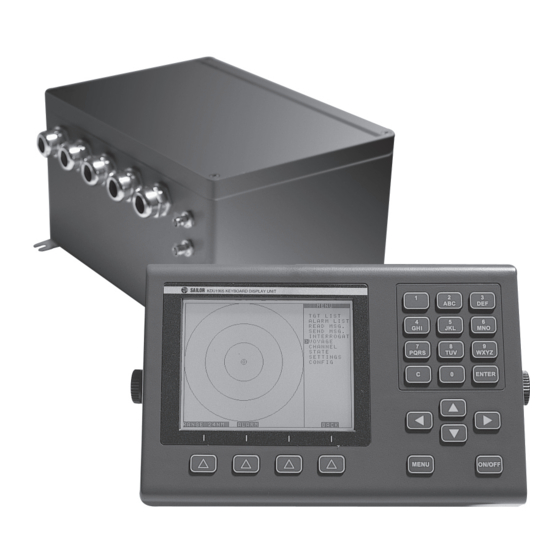
UAIS DEBEG 3400, Electronics Unit 2 Overview Technical Manual 2.9 DEBEG 3400 Electronics Unit DEBEG 3400 Electronics Unit Fig. 2-8 UAIS DEBEG 3400 Electronics Unit The aluminium housing contains a single Electronics Unit which consists of the controller, the interfaces, the VHF transmitter/receiver and the GPS receiver. - Page 22 2 Overview UAIS DEBEG 3400, Electronics Unit 2.9 DEBEG 3400 Electronics Unit Technical Manual ED3047G142 / 08 (2004-06) t_ue_e02.fm / 21.06.04...
-
Page 23: Installation Recommendations
UAIS DEBEG 3400, Electronics Unit 3 Installation Recommendations Technical Manual 3.1 General Recommendations Installation Recommendations General Recommendations 3.1.1 Cables Cable types, cable data, maximum cable length, special instructions for cable laying and connection details are defined in the Cabling Documents of the corresponding equipment (consisting of schematic diagram, remarks, cable list and connection diagram). -
Page 24: Maximum Cable Length
3 Installation Recommendations UAIS DEBEG 3400, Electronics Unit 3.1 General Recommendations Technical Manual In the case of a unit whose cable inlet consists of a hole with brackets attached on the inside and outside, the cable must be dressed as shown in Figure 3-1. Brackets Installation cables Metal clamp inside... -
Page 25: Cable Sets
UAIS DEBEG 3400, Electronics Unit 3 Installation Recommendations Technical Manual 3.1 General Recommendations 3.1.1.2 Cable Sets The following cable sets are available: Purpose/Description Quantity/m Order No. LAN network, cable RG 213/U, 2 BNC on request 300005394 connectors Connection of the GPS antenna, cable HF2,3LZ/7,3DZ with 2 plugs 11TNC-50-7- 271256324 Connection of the GPS antenna, cable... -
Page 26: Antennas
3 Installation Recommendations UAIS DEBEG 3400, Electronics Unit 3.1 General Recommendations Technical Manual This distance is measured from the centre of the magnetic system of the compass to the nearest point on the corresponding unit concerned. Units which are to be used on the bridge wing must be installed inside the "wing control console" - protected against the weather - if they do not at least correspond to the enclosure type IP 56. -
Page 27: Specific Recommendations
UAIS DEBEG 3400, Electronics Unit 3 Installation Recommendations Technical Manual 3.2 Specific Recommendations Specific Recommendations 3.2.1 Recommendations Concerning AIS Systems Recommendations for the installation of AIS systems are published in the document IMO Circular SN227 "Guidelines for the Installation of a Shipborne Automatic Identification System (AIS)". See this document for further information. -
Page 28: Recommendations Concerning The Installation Of The Vhf Antenna
3 Installation Recommendations UAIS DEBEG 3400, Electronics Unit 3.2 Specific Recommendations Technical Manual 3.2.3.1 Recommendations Concerning the Installation of the VHF Antenna Superstructures, Superstructures, e.g. deck house, e.g. deck house, Mast, boom, railing Mast, boom, railing funnel, funnel, with small diameter with small diameter (should be avoided) (should be avoided) -
Page 29: Recommendations Concerning The Installation Of The Gps Antenna
UAIS DEBEG 3400, Electronics Unit 3 Installation Recommendations Technical Manual 3.2 Specific Recommendations 3.2.3.2 Recommendations Concerning the Installation of the GPS Antenna Satellites Satellites Superstructures, Superstructures, e.g. deck house, e.g. deck house, funnel, funnel, Mast, boom Mast, boom with small diameter with small diameter Superstructures, Superstructures,... -
Page 30: Recommendations Concerning Redundancy
3 Installation Recommendations UAIS DEBEG 3400, Electronics Unit 3.2 Specific Recommendations Technical Manual 3.2.4 Recommendations Concerning Redundancy If possible, the Electronics Unit should be supplied with the ship’s sensor data from two different sources, e.g. in a dual installation with RADARPILOT 1000 the AIS can be supplied with sensor data from both radars. -
Page 31: Pilot Port, Connector/Cable Kits
UAIS DEBEG 3400, Electronics Unit 3 Installation Recommendations Technical Manual 3.2 Specific Recommendations 3.2.7 Pilot Port, Connector/Cable Kits The regulations for AIS systems prescribe a connector for the Pilot Port. This connector is standardized. The following kits are available: Consisting of Order No. - Page 32 3 Installation Recommendations UAIS DEBEG 3400, Electronics Unit 3.2 Specific Recommendations Technical Manual ED3047G142 / 08 (2004-06) t_ue_e03.fm / 21.06.04...
-
Page 33: Functional Description
UAIS DEBEG 3400, Electronics Unit 4 Functional Description Technical Manual 4.1 Block Diagram Functional Description The AIS system consists of the following components: DEBEG 3400 UAIS Electronics Unit GPS antenna 1330FB VHF antenna CXL 2-1 optional Display and Control Unit DEBEG 3401 The functionality is described in Section 4.1 by means of the block diagram (Figure 4-3). - Page 34 4 Functional Description UAIS DEBEG 3400, Electronics Unit 4.1 Block Diagram Technical Manual The DSC Receiver receives messages from external stations such as VTS. By means of the DSC messages, specific settings such as a change of the VHF channels can be controlled. The VHF transmitter/receiver has a limited range.
-
Page 35: Termination
UAIS DEBEG 3400, Electronics Unit 4 Functional Description Technical Manual 4.2 Termination Termination The wiring must be done in accordance with Figure 4-2 with 50 Ω coaxial cable (for example inside the enclosures, RG 58, for ship’s cabling RG 213 / U, see cabling diagrams). The network is a 10 Mbit network. -
Page 36: Description Of The Components
4 Functional Description UAIS DEBEG 3400, Electronics Unit 4.3 Description of the Components Technical Manual Description of the Components 4.3.1 DEBEG AIS 3400 Electronics Unit Antennas Electronics Unit Interfaces and Displays Mainboard Sensor Input Channels AIS - A RS422, IEC 61162 -1/2 Receiver (4800/38400 Baud) AIS - B... -
Page 37: Interfaces
UAIS DEBEG 3400, Electronics Unit 4 Functional Description Technical Manual 4.3 Description of the Components 4.3.1.1 Interfaces Connector 3 Connector 4 Sensor Input Channels, RS422, IEC 61162 -1/2 (4800/38400 Baud) Power Supply Input for ship’s sensors 8 0 V (and to fan, black wire) 8 GND 7 +24 V (and to fan, red wire) 7 GND... -
Page 38: Coaxial Connectors
4 Functional Description UAIS DEBEG 3400, Electronics Unit 4.3 Description of the Components Technical Manual 4.3.1.2 Coaxial Connectors Fig. 4-5 Internal coax wiring 4.3.1.3 Supported Sensor Input Sentences Prerequisites: NMEA Version 2.01 edition 04/1994 (corresponds to the first edition of IEC 61162) or higher is required. In addition the optional checksum is required. -
Page 39: Supported Sentences For The Ais Primary Display Port And The Pilot Port
UAIS DEBEG 3400, Electronics Unit 4 Functional Description Technical Manual 4.3 Description of the Components Input sentences in compliance with IEC 61162-1/-2 Required Sentence Optional Sentence Data (Identifier and Description) (Identifier and Description) Reference Datum DTM (Datum reference) Positioning System: - GNS (GNSS fix data) - RMC (Recommended minimum - Time of Position... - Page 40 4 Functional Description UAIS DEBEG 3400, Electronics Unit 4.3 Description of the Components Technical Manual Data Sentence Identifier/Description AIS VHF channel selection ACA (AIS channel assignment message) AIS VHF power setting ACA (AIS channel assignment message) AIS VHF channel bandwidth ACA (AIS channel assignment message) Transmit/Receive mode control ACA (AIS channel assignment message)
-
Page 41: Supported Sentences For The Long Range Port
UAIS DEBEG 3400, Electronics Unit 4 Functional Description Technical Manual 4.3 Description of the Components Data Sentence Identifier/Description Acknowledge to AIS transmitter status on/off AISTXD (acknowledge to AIS transmitter status) Report on a long range interrogation to the MKD AISLRF (AIS long range function request) AIS firmware version AISVER (AIS version) 4.3.1.5... -
Page 42: Supported Sentences For The Internal Position Sensor
4 Functional Description UAIS DEBEG 3400, Electronics Unit 4.3 Description of the Components Technical Manual Data Sentence Identifier/Description MMSI of responder LR1 (Long range response, line 1) MMSI of requester Ship’s name Ship’s call sign IMO number MMSI of responder LR2 (Long range response, line 2) Date and time of message composition Position... - Page 43 UAIS DEBEG 3400, Electronics Unit 4 Functional Description Technical Manual 4.3 Description of the Components Data Sentence Identifier/Description Global positioning system GNS (Global positioning system) - UTC (hhmmss.ss) - Latitude N/S (data and "N" or "S" or empty fields) - Longitude E/W (data and "E" or "W" or empty fields) - Mode indicator ( N=No fix A=Autonomous D=Differential...
-
Page 44: Iec 61162 -1/-2 Interfaces, Electrical Characteristics
4 Functional Description UAIS DEBEG 3400, Electronics Unit 4.3 Description of the Components Technical Manual 4.3.1.7 IEC 61162 -1/-2 Interfaces, Electrical Characteristics The interfaces comply with IEC 61162-1:2000 (2nd Edition) and IEC 61162-2:1998. The designation "-" in this manual corresponds to the designation "Line A" of IEC 61162 -1/-2. The designation "+"... -
Page 45: Examples For The Interconnection
UAIS DEBEG 3400, Electronics Unit 4 Functional Description Technical Manual 4.3 Description of the Components 4.3.1.8 Examples for the Interconnection Gyro Interface 9401 +24 V AIS Electronics Unit Common DCU 3401 RS422-1 Alarm make Alarm center 24 V DC IN Alarm break Alarm + 24 V... -
Page 46: Vhf Antenna
4 Functional Description UAIS DEBEG 3400, Electronics Unit 4.3 Description of the Components Technical Manual +24 V AIS Electronics Unit DCU 3401 RS422-1 Alarm make Alarm center 24 V DC IN Alarm break Alarm + 24 V Terminals yard supply 5 4 1 Pilot Plug Fig. -
Page 47: Gps Antenna
UAIS DEBEG 3400, Electronics Unit 4 Functional Description Technical Manual 4.3 Description of the Components 4.3.3 GPS Antenna The GPS antenna 1330 is a GPS L1 antenna for a frequency of 1575.42 ±10 MHz with an integrated amplifier. For the technical data see Section 7, for installation instructions see Section 3. 4.3.4 Pilot Port For the Pilot Port must be connected as prescribed in the regulations. - Page 48 4 Functional Description UAIS DEBEG 3400, Electronics Unit 4.3 Description of the Components Technical Manual ED3047G142 / 08 (2004-06) t_ue_e04.fm / 21.06.04...
-
Page 49: Setting-To-Work/Configuration
UAIS DEBEG 3400, Electronics Unit 5 Setting-to-Work/Configuration Technical Manual 5.1 Setting-to-Work Setting-to-Work/Configuration Setting-to-Work The AIS Electronics Unit and the antennas must be installed as described in Section 3 (I n s t a l l a t i o n R e c o m m e n d a t i o n s ). -
Page 50: Configuration With Dcu Debeg 3401
5 Setting-to-Work/Configuration UAIS DEBEG 3400, Electronics Unit 5.4 Testing Technical Manual 5.3.1 Configuration with DCU DEBEG 3401 It is necessary to configure the DCU. For information in detail see the Technical Manual of the DCU DEBEG 3401. 5.3.2 Configuration with RADARPILOT/CHARTRADAR/MULTIPILOT 1000 - NACOS xx-4 Systems It is necessary to configure the radar and the interfaces. -
Page 51: Repair/Maintenance
UAIS DEBEG 3400, Electronics Unit 6 Repair/Maintenance Technical Manual 6.1 Trouble Shooting Repair/Maintenance GENERAL: The jumper settings and switch settings on a replacement pcb must be the same as on the defective pcb. The wire connections must be made in exactly the same way. Exceptions are explained in this manual. Trouble Shooting 6.1.1 Hints... -
Page 52: Trouble Shooting For Uais Debeg 3400 Connected To A Radarpilot 1000
6 Repair/Maintenance UAIS DEBEG 3400, Electronics Unit 6.1 Trouble Shooting Technical Manual 6.1.2 Trouble Shooting for UAIS DEBEG 3400 connected to a RADARPILOT 1000 6.1.2.1 Indication: System Fault Message 3617 Displayed on Indicator NOTE: The following instructions are valid only, if the AIS is connected via the Primary Display Port. The UAIS DEBEG 3400 Electronics Unit can also be connected via the Ethernet LAN (RADARPILOT/CHAR- TRADAR 1000 with software 3.0 or newer or MULTIPILOT 1000). -
Page 53: Fig. 6-2 Protocol Radar Txd
UAIS DEBEG 3400, Electronics Unit 6 Repair/Maintenance Technical Manual 6.1 Trouble Shooting Path: Configure > Radar > Indicator > Indicator x > Serial Interfaces > Serial I/O x Parameters: Driver, set to NMEA183 (IEC 61162-1/2) Baud Rate, set to 38400 Wind, set to Connected (if the interface has been used for a ship’s sensor with NMEA183 (IEC 61162-1/2) protocol beforehand, it is not necessary to modify this parameter.) The Serial I/O Monitor must be started. -
Page 54: Fig. 6-3 Cable Connection For The Interface Monitoring Ais > Radar
6 Repair/Maintenance UAIS DEBEG 3400, Electronics Unit 6.1 Trouble Shooting Technical Manual Test of the UAIS DEBEG 3400 Output Power Down the system Connect the AIS Primary Display Port TB7 and TB8 additionally to an indicator serial interface (TB1) of the radar. If there is a free input, this one should be used. If all inputs are used, one of them must be disconnected. -
Page 55: Fig. 6-4 Protocol Ais Txd
UAIS DEBEG 3400, Electronics Unit 6 Repair/Maintenance Technical Manual 6.1 Trouble Shooting Status messages of the connected sensors, sent every minute !AIVDO,2,2,0,B,00000000000,2*25 !AIVDO,1,1,,,139K6D7037H@L7FBOLDCr39R0000,0*3D !AIVDO,1,1,,A,139K6D7037H@L7FBOLDCr39R08AM,0*78 !AIVDO,1,1,,,139K6D7037H@L9:BOLBCr39T0000,0*4F $AITXT,1,1,31,AIS: Heading valid*0D $AITXT,1,1,34,AIS: Other ROT source in use*62 !AIVDO,1,1,,,139K6D7037H@L;DBOL=kr39V0000,0*66 !AIVDM,1,1,,B,1000O@B038H@L:vBOL>Cr39V08Bg,0*65 !AIVDO,1,1,,,139K6D7037H@L=FBOL;kr39`0000,0*52 Position report !AIVDO,1,1,,,139K6D7037H@L?LBOL9kr39b0000,0*5A !AIVDO,1,1,,B,139K6D7037H@L?LBOL9kr39b0D01,0*6D !AIVDO,1,1,,,139K6D7037H@LALBOL7Sr39d0000,0*14 !AIVDO,1,1,,,139K6D7037H@LC<BOL5Sr39f0000,0*66... -
Page 56: Indication: System Fault Message 3616 Displayed On Indicator
6 Repair/Maintenance UAIS DEBEG 3400, Electronics Unit 6.2 Test of the Antenna Performance Technical Manual 6.1.2.2 Indication: System Fault Message 3616 Displayed on Indicator If the system fault message 3616 is displayed, it is likely that the problems are caused by the Analog Interface if the AIS is connected via the Primary Display Port. -
Page 57: Software Update
UAIS DEBEG 3400, Electronics Unit 6 Repair/Maintenance Technical Manual 6.3 Software Update Software Update A software update can be performed by means of a laptop (or any other PC with Windows 95, 98, XP as its operating system), a cable and the service software, which is available in the SAM-CMIS system (see Section 6.3.1). -
Page 58: Determination Of The Current Software Versions
6 Repair/Maintenance UAIS DEBEG 3400, Electronics Unit 6.3 Software Update Technical Manual 6.3.2 Determination of the Current Software Versions UAIS DEBEG 3400 with RADAR/CHARTRADAR/MULTIOPILOT 1000 Open the System Maintenance Manager by clicking Menu -> Utilities -> Maintenance. Select the register card Telemonitoring Data and click on the Version button at the lower left. The software versions of the radar and of connected systems are displayed. -
Page 59: Serial Cable Connection
UAIS DEBEG 3400, Electronics Unit 6 Repair/Maintenance Technical Manual 6.3 Software Update 6.3.3 Serial Cable Connection Serial Cable A cable is delivered with the Electronics Unit, it can be ordered from the manufacturer (see Section 6.3.1.1) or it can be made as described below. The wiring of the cable must be as follows: PC (COM port) Electronics Unit... -
Page 60: Software Update By Means Of A Laptop
6 Repair/Maintenance UAIS DEBEG 3400, Electronics Unit 6.3 Software Update Technical Manual Connection at the PC/Laptop serial cable must connected to COM 1 of the PC/ Laptop. COM 1 Fig. 6-7 Connection to the Laptop Connection at the Electronics Unit The cable must be connected to the serial service interface of the computer and to the connector on the top of the Electronics Unit’s pcb. - Page 61 UAIS DEBEG 3400, Electronics Unit 6 Repair/Maintenance Technical Manual 6.3 Software Update To start the update software open the directory of the software version which shall be installed (usually the newest version; for details see the readme file) DOS command line: CD X:\AIS\ElectronicsUnit\BuildNNN_YYYYMMDD\root (DRIVE X name of the drive, NNN = release of the software, YYYY=year, MM=month, DD=day) Type aisupdate.exe to start the software.
-
Page 62: Software Update By Means Of A Chartpilot Or Multipilot 91X0
6 Repair/Maintenance UAIS DEBEG 3400, Electronics Unit 6.3 Software Update Technical Manual The Electronics Unit reboots automatically. The OK button closes the window of the update routine. 10. Verify the proper function of the system, make sure that AIS targets and sensor data will be displayed on the connected display system. -
Page 63: Opening The Housing
UAIS DEBEG 3400, Electronics Unit 6 Repair/Maintenance Technical Manual 6.4 Opening the Housing Opening the Housing Fig. 6-9 Opening of the Electronics Unit housing Undo the four screws in the cover. The screws cannot be removed. Disconnect the grounding cable from the cover. -
Page 64: Exchange Of Parts And Testing
6 Repair/Maintenance UAIS DEBEG 3400, Electronics Unit 6.6 Exchange of Parts and Testing Technical Manual Exchange of Parts and Testing 6.6.1 Electronics Unit If the Electronics Unit is defective, the complete Electronics Module inside the housing must be exchanged. For the exchange, proceed as follows: Disconnect/switch the AIS from the mains supply. -
Page 65: Housing Fan (Newer Versions Only)
UAIS DEBEG 3400, Electronics Unit 6 Repair/Maintenance Technical Manual 6.6 Exchange of Parts and Testing 6.6.2 Housing Fan (newer Versions only) air flow Open the housing of the Electronics Unit as described in Section 6.4. The fan is mounted by means of four screws. To unmount the fan, remove the screws. To fix the new fan, proceed in reverse order. - Page 66 6 Repair/Maintenance UAIS DEBEG 3400, Electronics Unit 6.6 Exchange of Parts and Testing Technical Manual Remove four screws on top of the frame’s side- wall with the fan. Cant the sidewall to the outside. Remove the three screws of the fan and disconnect the connector to exchange it.
-
Page 67: Antennas
UAIS DEBEG 3400, Electronics Unit 6 Repair/Maintenance Technical Manual 6.6 Exchange of Parts and Testing Proceed in reverse order to mount the new fan and to close the housing. Take care that the connec- tors fit together during mounting the upper pcb. Verify the function of the fan after power on. -
Page 68: Maintenance
6 Repair/Maintenance UAIS DEBEG 3400, Electronics Unit 6.7 Maintenance Technical Manual Maintenance Internal Fan It is recommended to check the fan inside the Electronics Unit housing every three month. This can be performed by the operator or during service work. It must be checked: whether the fan is running (noticeable airflow) and whether noise is indicating damaged bearings. -
Page 69: Spare Parts
UAIS DEBEG 3400, Electronics Unit 6 Repair/Maintenance Technical Manual 6.8 Spare Parts Spare Parts 6.8.1 Spare Part List Some of the components may be modified at short intervals, so that it is likely that it will not be possible to deliver spare parts which are absolutely identical to the original part. In such cases, a Technote for the exchange is delivered with the spare part and new versions of components are added to this manual as soon as possible. - Page 70 6 Repair/Maintenance UAIS DEBEG 3400, Electronics Unit 6.8 Spare Parts Technical Manual ED3047G142 / 08 (2004-06) t_ue_e07.fm / 21.06.04...
-
Page 71: Technical Data
UAIS DEBEG 3400, Electronics Unit 7 Technical Data Technical Manual 7.1 Conformity to Standards, Environmental Conditions Technical Data Conformity to Standards, Environmental Conditions The UAIS DEBEG 3400 Electronics Unit complies with DIN EN 60945 (Maritime navigation and radio- communication equipment and systems - General requirements - Methods of testing and required test results). -
Page 72: Performance Data Of The Vhf Antenna Clx 2-1/150-170 Mhz
7 Technical Data UAIS DEBEG 3400, Electronics Unit 7.2 Performance Technical Manual 7.2.2 Performance Data of the VHF Antenna CLX 2-1/150-170 MHz Antenna type: ½λ coaxial, broad band Frequency: 150...170 MHz Nom. 50 Ω Impedance: Polarization: Vertical Gain: 2 dBi, 0 dBd Bandwith: 20 MHz SWR:... -
Page 73: Performance Data Of The Gps Antenna
UAIS DEBEG 3400, Electronics Unit 7 Technical Data Technical Manual 7.3 Dimensions and Weights 7.2.3 Performance Data of the GPS Antenna General: Color: White Weight: 163 g Nominal RF input: TNC female Operating temperature: -40...+85°C Humidity: 95% relative humidity Antenna Element: Frequency: 1575.42 ±10.0 MHz 50 Ω... - Page 74 7 Technical Data UAIS DEBEG 3400, Electronics Unit 7.4 Compass Safe Distances Technical Manual ED3047G142 / 08 (2004-06) t_ue_e08.fm / 21.06.04...
-
Page 75: Fault Code List
UAIS DEBEG 3400, Electronics Unit 8 Fault Code List Technical Manual Fault Code List The following fault codes (integrity alarm conditions) can be displayed at the connected display unit (for example a DCU or a RADARPILOT 1000). See also Section 6 from page 51 on for further information. Messages at Error Message generated by, 1000 Series,... - Page 76 8 Fault Code List UAIS DEBEG 3400, Electronics Unit Technical Manual Messages at Error Message generated by, 1000 Series, Radar 9xxx, Possible Cause/Source, CHART- Fault MULTIPILOT Reaction of the System, PILOT, MULTI- 910x (Radar Remedy PLOT 910x Mode) (Chart Mode) Generated by: AIS Electronics Unit Cause/Source: No valid position data at interface S1, S2, AIS: External...
- Page 77 UAIS DEBEG 3400, Electronics Unit 8 Fault Code List Technical Manual Messages at Error Message generated by, 1000 Series, Radar 9xxx, Possible Cause/Source, CHART- Fault MULTIPILOT Reaction of the System, PILOT, MULTI- 910x (Radar Remedy PLOT 910x Mode) (Chart Mode) Generated by: AIS Electronics Unit Cause/Source: No data from external sensor AIS: No valid...
- Page 78 8 Fault Code List UAIS DEBEG 3400, Electronics Unit Technical Manual Messages at Error Message generated by, 1000 Series, Radar 9xxx, Possible Cause/Source, CHART- Fault MULTIPILOT Reaction of the System, PILOT, MULTI- 910x (Radar Remedy PLOT 910x Mode) (Chart Mode) Generated by: DCU, Internal Test 0113 Error while writing byte (RS422-2)
- Page 79 UAIS DEBEG 3400, Electronics Unit 8 Fault Code List Technical Manual Messages at Error Message generated by, 1000 Series, Radar 9xxx, Possible Cause/Source, CHART- Fault MULTIPILOT Reaction of the System, PILOT, MULTI- 910x (Radar Remedy PLOT 910x Mode) (Chart Mode) Generated by: AIS Electronics Unit Cause/Source: The transmitter has been switched off completely by the operator, the MMSI number has not...
- Page 80 8 Fault Code List UAIS DEBEG 3400, Electronics Unit Technical Manual ED3047G142 / 08 (2004-06) t_ue_e09.fm / 21.06.04...
-
Page 81: Cabling Documents
UAIS DEBEG 3400, Electronics Unit 9 Cabling Documents Technical Manual Cabling Documents Grounding All components of the radar system have contacts such as bolts or terminals for grounding. Grounding is important for EMC purposes as well as for protecting people’s lives. Both purposes are covered by the standard grounding of the system’s housings to the ship’s metallic structure (bolted or welded). -
Page 82: Fig. 9-1 Cable Diagram 1/6, Connection To Dcu Debeg 3401 Via Primary Display Port
UAIS DEBEG 3400, Electronics Unit 9 Cabling Documents Technical Manual Fig. 9-1 Cable Diagram 1/6, connection to DCU DEBEG 3401 via Primary Display Port ED3047G142 / 08 (2004-06) t_ue_e11.fm / 21.06.04... -
Page 83: Fig. 9-2 Cable Diagram 2/6, Connection To Radarpilot 1000/Nacos Xx-4 Via Primary Display Port
UAIS DEBEG 3400, Electronics Unit 9 Cabling Documents Technical Manual Fig. 9-2 Cable Diagram 2/6, connection to RADARPILOT 1000/NACOS xx-4 via Primary Display Port ED3047G142 / 08 (2004-06) t_ue_e11.fm / 21.06.04... -
Page 84: Fig. 9-3 Cable Diagram 3/6, Connection To Chartpilot, Nacos-Xx4, Radar / Multipilot 1000 Via
UAIS DEBEG 3400, Electronics Unit 9 Cabling Documents Technical Manual Fig. 9-3 Cable Diagram 3/6, connection to CHARTPILOT, NACOS-xx4, RADAR / MULTIPILOT 1000 via LAN ED3047G142 / 08 (2004-06) t_ue_e11.fm / 21.06.04... -
Page 85: Fig. 9-4 Cable Diagram 4/6, Connection To Chartpilot Stand-Alone
UAIS DEBEG 3400, Electronics Unit 9 Cabling Documents Technical Manual Fig. 9-4 Cable Diagram 4/6, connection to CHARTPILOT stand-alone ED3047G142 / 08 (2004-06) t_ue_e11.fm / 21.06.04... -
Page 86: Fig. 9-5 Cable Diagram 5/6, Connection To Radar 9Xxx Via Radar 9Xxx Ais Interface (Nacos Xx-3)
UAIS DEBEG 3400, Electronics Unit 9 Cabling Documents Technical Manual Fig. 9-5 Cable Diagram 5/6, connection to Radar 9xxx via Radar 9xxx AIS Interface (NACOS xx-3) ED3047G142 / 08 (2004-06) t_ue_e11.fm / 21.06.04... -
Page 87: Fig. 9-6 Cable Diagram 6/6, Connection To Dcu Debeg 3401 And Gyro Converter Debeg 4901
UAIS DEBEG 3400, Electronics Unit 9 Cabling Documents Technical Manual Fig. 9-6 Cable Diagram 6/6, connection to DCU DEBEG 3401 and Gyro Converter DEBEG 4901 ED3047G142 / 08 (2004-06) t_ue_e11.fm / 21.06.04... -
Page 88: Fig. 9-7 Connection Diagram 1/10, Connection To Dcu Degeg 3401
UAIS DEBEG 3400, Electronics Unit 9 Cabling Documents Technical Manual Fig. 9-7 Connection Diagram 1/10, connection to DCU DEGEG 3401 ED3047G142 / 08 (2004-06) t_ue_e11.fm / 21.06.04... -
Page 89: Fig. 9-8 Connection Diagram 2/10, Dcu Connectors (Alarm Input, Primary Display Port, Power Supply)
UAIS DEBEG 3400, Electronics Unit 9 Cabling Documents Technical Manual Fig. 9-8 Connection Diagram 2/10, DCU connectors (alarm input, Primary Display Port, power supply) ED3047G142 / 08 (2004-06) t_ue_e11.fm / 21.06.04... -
Page 90: Fig. 9-9 Connection Diagram 3/10, Connection To Nacos Xx-4, Radar/Multipilot 1000 Via Prim
UAIS DEBEG 3400, Electronics Unit 9 Cabling Documents Technical Manual Fig. 9-9 Connection Diagram 3/10, connection to NACOS xx-4, RADAR/MULTIPILOT 1000 via Prim. Displ. Port ED3047G142 / 08 (2004-06) t_ue_e11.fm / 21.06.04... -
Page 91: Fig. 9-10 Connection Diagram 4/10, Terminals At The Analog Interface
UAIS DEBEG 3400, Electronics Unit 9 Cabling Documents Technical Manual Fig. 9-10 Connection Diagram 4/10, terminals at the Analog Interface ED3047G142 / 08 (2004-06) t_ue_e11.fm / 21.06.04... -
Page 92: Fig. 9-11 Connection Diagram 5/10, Connection To Chartpilot, Nacos, Radar/Multipilot 1000 Via
UAIS DEBEG 3400, Electronics Unit 9 Cabling Documents Technical Manual Fig. 9-11 Connection Diagram 5/10, connection to CHARTPILOT, NACOS, RADAR/MULTIPILOT 1000 via LAN ED3047G142 / 08 (2004-06) t_ue_e11.fm / 21.06.04... -
Page 93: Fig. 9-12 Connection Diagram 6/10, Connection To Chartpilot Stand-Alone Systems
UAIS DEBEG 3400, Electronics Unit 9 Cabling Documents Technical Manual Fig. 9-12 Connection Diagram 6/10, connection to CHARTPILOT stand-alone systems ED3047G142 / 08 (2004-06) t_ue_e11.fm / 21.06.04... -
Page 94: Fig. 9-13 Connection Diagram 7/10, Connection To Radar 9Xxx Via Radar 9Xxx Ais Interface (Nacos Xx-3)
UAIS DEBEG 3400, Electronics Unit 9 Cabling Documents Technical Manual Fig. 9-13 Connection Diagram 7/10, connection to Radar 9xxx via Radar 9xxx AIS Interface (NACOS xx-3) ED3047G142 / 08 (2004-06) t_ue_e11.fm / 21.06.04... -
Page 95: Fig. 9-14 Connection Diagram 8/10, Terminals At The Gyro Converter Unit Debeg 4901
UAIS DEBEG 3400, Electronics Unit 9 Cabling Documents Technical Manual Fig. 9-14 Connection Diagram 8/10, terminals at the Gyro Converter Unit DEBEG 4901 ED3047G142 / 08 (2004-06) t_ue_e11.fm / 21.06.04... -
Page 96: Fig. 9-15 Connection Diagram 9/10, Connection To Dcu Debeg 3401 And Gyro Converter Unit Debeg
UAIS DEBEG 3400, Electronics Unit 9 Cabling Documents Technical Manual Fig. 9-15 Connection Diagram 9/10, connection to DCU DEBEG 3401 and Gyro Converter Unit DEBEG 4901 ED3047G142 / 08 (2004-06) t_ue_e11.fm / 21.06.04... -
Page 97: Fig. 9-16 Connection Diagram 10/10, Terminals Of The Radar 9Xxx Ais Interface
UAIS DEBEG 3400, Electronics Unit 9 Cabling Documents Technical Manual Fig. 9-16 Connection Diagram 10/10, terminals of the Radar 9xxx AIS Interface ED3047G142 / 08 (2004-06) t_ue_e11.fm / 21.06.04... -
Page 98: Fig. 9-17 Cable Diagram 1/1, Antenna Cables Longer Than 40 M
UAIS DEBEG 3400, Electronics Unit 9 Cabling Documents Technical Manual Fig. 9-17 Cable Diagram 1/1, Antenna cables longer than 40 m ED3047G142 / 08 (2004-06) t_ue_e11.fm / 21.06.04... -
Page 99: 10 Outline Drawings
UAIS DEBEG 3400, Electronics Unit 10 Outline Drawings Technical Manual Outline Drawings Title Page U A I S D E B E G 3 4 0 0 E l e c t r o n i c s U n i t , N G 3 0 3 0 G 0 1 0 M B , c u r r e n t v e r s i o n o f t h e h o u s i n g U A I S D E B E G 3 4 0 0 E l e c t r o n i c s U n i t , N G 3 0 3 0 G 0 1 0 M B , f o r m e r v e r s i o n o f t h e h o u s i n g A I S G P S a n t e n n a , 1 / 2 A I S G P S a n t e n n a , 2 / 2... -
Page 100: Fig. 10-1 Uais Debeg 3400 Electronics Unit, Ng3030G010Mb, Current Version Of The Housing
UAIS DEBEG 3400, Electronics Unit 10 Outline Drawings Technical Manual Fig. 10-1 UAIS DEBEG 3400 Electronics Unit, NG3030G010MB, current version of the housing ED3047G142 / 08 (2004-06) t_ue_e12.fm / 21.06.04... -
Page 101: Fig. 10-2 Uais Debeg 3400 Electronics Unit, Ng3030G010Mb, Former Version Of The Housing
UAIS DEBEG 3400, Electronics Unit 10 Outline Drawings Technical Manual Fig. 10-2 UAIS DEBEG 3400 Electronics Unit, NG3030G010MB, former version of the housing ED3047G142 / 08 (2004-06) t_ue_e12.fm / 21.06.04... -
Page 102: Fig. 10-3 Ais Gps Antenna, 1/2
UAIS DEBEG 3400, Electronics Unit 10 Outline Drawings Technical Manual All dimensions are indicated as inches. Fig. 10-3 AIS GPS antenna, 1/2 ED3047G142 / 08 (2004-06) t_ue_e12.fm / 21.06.04... -
Page 103: Fig. 10-4 Ais Gps Antenna, 2/2
UAIS DEBEG 3400, Electronics Unit 10 Outline Drawings Technical Manual Fig. 10-4 AIS GPS antenna, 2/2 ED3047G142 / 08 (2004-06) t_ue_e12.fm / 21.06.04... -
Page 104: Fig. 10-5 Ais Vhf Antenna
UAIS DEBEG 3400, Electronics Unit 10 Outline Drawings Technical Manual Fig. 10-5 AIS VHF antenna ED3047G142 / 08 (2004-06) t_ue_e12.fm / 21.06.04... -
Page 105: Notes
UAIS DEBEG 3400, Electronics Unit Notes Technical Manual Notes Space for your notes. ED3047G142 / 08 (2004-06) t_ue_eno.fm / 21.06.04... - Page 106 Notes UAIS DEBEG 3400, Electronics Unit Technical Manual ED3047G142 / 08 (2004-06) t_ue_eno.fm / 21.06.04...
Need help?
Do you have a question about the UAIS1900 and is the answer not in the manual?
Questions and answers