Sign In
Upload
Manuals
Brands
Sailor Manuals
Marine Radio
UAIS1900
User Manuals: Sailor UAIS1900 Universal AIS Transponder
Manuals and User Guides for Sailor UAIS1900 Universal AIS Transponder. We have
1
Sailor UAIS1900 Universal AIS Transponder manual available for free PDF download: Technical Manual
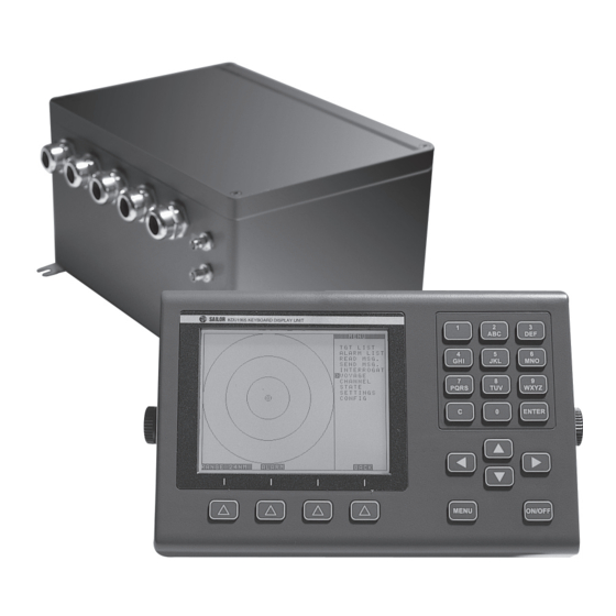
Sailor UAIS1900 Technical Manual (108 pages)
Universal AIS Transponder
Brand:
Sailor
| Category:
Marine Radio
| Size: 5 MB
Table of Contents
Table of Contents
3
List of Contents
3
Ed3047G142 / 08 (2004
6
List of Figures
7
List of Abbreviations
9
1 General
11
Software Releases
11
General Recommendations for Installation, Maintenance and Repair Work
11
Safety Warnings
11
2 Overview
13
Compatibility with Other Systems
13
UAIS DEBEG 3400 with DCU DEBEG 3401
14
Fig. 2-1 UAIS DEBEG 3400 with DCU DEBEG 3401
14
UAIS DEBEG 3400 in RADARPILOT 1000 Systems
15
Fig. 2-2 UAIS DEBEG 3400 in RADARPILOT 1000 Systems
15
UAIS DEBEG 3400 in 1000 Series Systems (NACOS XX-4)
16
Fig. 2-3 UAIS DEBEG 3400, SAM Electronics 1000 Series Systems (NACOS XX-4)
16
UAIS DEBEG 3400 in CHARTPILOT Stand-Alone Systems
17
Fig. 2-4 UAIS DEBEG 3400 with CHARTPILOT Stand-Alone
17
UAIS DEBEG 3400 in NACOS XX-3 Systems (Radar 9Xxx and CHARTPILOT)
18
Fig. 2-5 UAIS DEBEG 3400 in NACOS XX-3 Systems
18
UAIS DEBEG 3400 in Radar 9Xxx Systems with RADARPILOT 1000
19
Fig. 2-6 UAIS DEBEG 3400 in Radar 9Xxx Systems with RADARPILOT 1000
19
UAIS DEBEG 3400 in Radar 9Xxx Systems
20
Fig. 2-7 UAIS DEBEG 3400 in Radar 9Xxx Systems
20
DEBEG 3400 Electronics Unit
21
Fig. 2-8 UAIS DEBEG 3400 Electronics Unit
21
3 Installation Recommendations
23
General Recommendations
23
Cables
23
Maximum Cable Length
24
Fig. 3-1 Cable Inlet Consisting of a Hole with Brackets
24
Cable Sets
25
Electronics Units
25
Antennas
26
Specific Recommendations
27
Recommendations Concerning AIS Systems
27
Recommendations Concerning the Installation of the Electronics Unit
27
Recommendations Concerning the Installation of the Antennas
27
Fig. 3-2 Minimum Distances for GPS and VHF Antenna
27
Recommendations Concerning the Installation of the VHF Antenna
28
Fig. 3-3 Positioning of the VHF Antenna
28
Recommendations Concerning the Installation of the GPS Antenna
29
Fig. 3-4 Positioning of the GPS Antenna
29
Fig. 3-5 Minimum Distances for the GPS Antenna from a Radar Scanner
29
Recommendations Concerning Redundancy
30
Recommendations Concerning the Connection of a (D)GPS to UAIS DBEG 3400
30
Emergency Power Source
30
Pilot Port, Connector/Cable Kits
31
Recommendations Concerning UAIS Stand-Alone with Radar 9Xxx / NACOS XX-2/-3
31
Recommendations Concerning the Connection to a SAM 1000 Series System
31
4 Functional Description
33
Block Diagram
33
Fig. 4-1 Block Diagram of the AIS System
33
Termination
35
Fig. 4-2 Principle of Wiring for Ethernet LAN
35
Description of the Components
36
DEBEG AIS 3400 Electronics Unit
36
Fig. 4-3 Block Diagram of the Electronics Unit
36
Fig. 10-3 Fig
36
Interfaces
37
Fig. 4-4 Interfaces of the DEBEG UAIS 3400 Electronics Unit
37
Coaxial Connectors
38
Supported Sensor Input Sentences
38
Fig. 4-5 Internal Coax Wiring
38
Supported Sentences for the AIS Primary Display Port and the Pilot Port
39
Supported Sentences for the Long Range Port
41
Supported Sentences for the Internal Position Sensor
42
IEC 61162 -1/-2 Interfaces, Electrical Characteristics
44
Examples for the Interconnection
45
Fig. 4-6 AIS Stand-Alone with DCU and Gyro Interface 9401
45
VHF Antenna
46
Fig. 4-7 AIS Stand-Alone with DCU
46
GPS Antenna
47
Pilot Port
47
Fig. 4-8 Pilot Port, Connector Assignment, Front View (Pins)
47
5 Setting-To-Work/Configuration
49
Setting-To-Work
49
Software Versions
49
Configuration
49
Configuration with DCU DEBEG 3401
50
Configuration with RADARPILOT/CHARTRADAR/MULTIPILOT 1000 - NACOS XX-4 Systems
50
Configuration with CHARTPILOT 93Xx in NACOS XX-3 Systems
50
Configuration with Radar 9Xxx
50
Testing
50
6 Repair/Maintenance
51
Trouble Shooting
51
Hints
51
Trouble Shooting for UAIS DEBEG 3400 Connected to a RADARPILOT 1000
52
Indication: System Fault Message 3617 Displayed on Indicator
52
Fig. 6-1 Cable Connection for the Interface Monitoring Radar > AIS
52
Fig. 6-2 Protocol Radar Txd
53
Fig. 6-3 Cable Connection for the Interface Monitoring AIS > Radar
54
Fig. 6-4 Protocol AIS Txd
55
Indication: System Fault Message 3616 Displayed on Indicator
56
Test of the Antenna Performance
56
Software Update
57
Access to Update Software and Update Accessories
57
Accessories for the Software Update
57
Software Download from SAM-CMIS
57
Determination of the Current Software Versions
58
Serial Cable Connection
59
Fig. 6-6 Suggestion for an Update Cable
59
Software Update by Means of a Laptop
60
Fig. 6-8 Service Interface
60
Software Update by Means of a CHARTPILOT or MULTIPILOT 91X0
62
Opening the Housing
63
Fuses
63
Fig. 6-9 Opening of the Electronics Unit Housing
63
Exchange of Parts and Testing
64
Electronics Unit
64
Fig. 6-10 Exchange of the Electronics Module
64
Housing Fan (Newer Versions Only)
65
Internal Fan
65
Antennas
67
Maintenance
68
Fig. 6-11 Position of the Fan
68
Spare Parts
69
Spare Part List
69
7 Technical Data
71
Conformity to Standards, Environmental Conditions
71
Performance
71
Performance Data of the Electronics Unit
71
Performance Data of the VHF Antenna CLX 2-1/150-170 Mhz
72
Performance Data of the GPS Antenna
73
Dimensions and Weights
73
Compass Safe Distances
73
8 Fault Code List
75
9 Cabling Documents
81
Fig. 9-1 Cable Diagram 1/6, Connection to DCU DEBEG 3401 Via Primary Display Port
82
Fig. 9-2 Cable Diagram 2/6, Connection to RADARPILOT 1000/NACOS XX-4 Via Primary Display Port
83
Fig. 9-3 Cable Diagram 3/6, Connection to CHARTPILOT, NACOS-Xx4, RADAR / MULTIPILOT 1000 Via
84
Lan
84
Fig. 9-4 Cable Diagram 4/6, Connection to CHARTPILOT Stand-Alone
85
Fig. 9-5 Cable Diagram 5/6, Connection to Radar 9Xxx Via Radar 9Xxx AIS Interface (NACOS XX-3)
86
Fig. 9-6 Cable Diagram 6/6, Connection to DCU DEBEG 3401 and Gyro Converter DEBEG 4901
87
Fig. 9-7 Connection Diagram 1/10, Connection to DCU DEGEG 3401
88
Fig. 9-8 Connection Diagram 2/10, DCU Connectors (Alarm Input, Primary Display Port, Power Supply)
89
Fig. 9-9 Connection Diagram 3/10, Connection to NACOS XX-4, RADAR/MULTIPILOT 1000 Via Prim
90
Displ. Port
90
Fig. 9-10 Connection Diagram 4/10, Terminals at the Analog Interface
91
Fig. 9-11 Connection Diagram 5/10, Connection to CHARTPILOT, NACOS, RADAR/MULTIPILOT 1000 Via
92
Lan
92
Fig. 9-12 Connection Diagram 6/10, Connection to CHARTPILOT Stand-Alone Systems
93
Fig. 9-13 Connection Diagram 7/10, Connection to Radar 9Xxx Via Radar 9Xxx AIS Interface (NACOS XX-3)
94
Fig. 9-14 Connection Diagram 8/10, Terminals at the Gyro Converter Unit DEBEG 4901
95
Fig. 9-15 Connection Diagram 9/10, Connection to DCU DEBEG 3401 and Gyro Converter Unit DEBEG
96
Fig. 9-16 Connection Diagram 10/10, Terminals of the Radar 9Xxx AIS Interface
97
Fig. 9-17 Cable Diagram 1/1, Antenna Cables Longer than 40 M
98
10 Outline Drawings
99
Fig. 10-1 UAIS DEBEG 3400 Electronics Unit, NG3030G010MB, Current Version of the Housing
100
Fig. 10-2 UAIS DEBEG 3400 Electronics Unit, NG3030G010MB, Former Version of the Housing
101
Fig. 10-3 AIS GPS Antenna, 1/2
102
Fig. 10-4 AIS GPS Antenna, 2/2
103
Fig. 10-5 AIS VHF Antenna
104
Notes
105
Advertisement
Advertisement
Related Products
Sailor A1 Basic VHF
Sailor A1 VHF-DSC
Sailor C4900
Sailor C4901
Sailor RT4722
Sailor RT5020 VHF DSC Duplex
Sailor RT5022 VHF DSC
Sailor Sailor 6300 MF/HF DSC
Sailor Categories
Radio
Transceiver
Marine Equipment
Marine Radio
Receiver
More Sailor Manuals
Login
Sign In
OR
Sign in with Facebook
Sign in with Google
Upload manual
Upload from disk
Upload from URL