Table of Contents
Advertisement
Advertisement
Table of Contents

Subscribe to Our Youtube Channel
Related Manuals for Sailor RT4722


Summary of Contents for Sailor RT4722
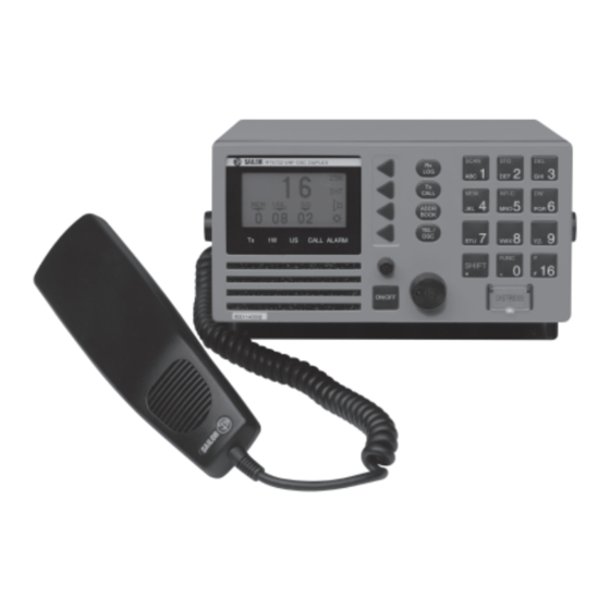
- Page 1 SAILOR RT4722 VHF-DSC DUPLEX Installation Manual...
- Page 2 Products with an annually updated training are ready to provide service 24 The SAILOR COMPACT 2000 GMDSS is based on the well proven hours a day, 365 days a year. range of Sailor products specifically developed to meet the GMDSS...
-
Page 3: Table Of Contents
RT4722 Contents Technical Specification ............................. 2 Installation ................................4 Mounting Possibilities ............................4 Power Supply ............................... 7 Aerial ..................................7 2.3.1 Placing the Aerials ..............................8 Handset Connection ............................. 8 Loudspeaker Connection ............................. 9 Connectors ................................9 2.6.1 SPARC-Bus Cable ............................... 10 2.6.2 Options Connector H4992 ........................... -
Page 4: Technical Specification
Technical Specification RT4722 1 Technical Specification Conforms to all relevant international requirements and resolutions as agreed by ETSI, IEC, ITU, and IMO as well as other national requirements. These specifications include ETS 300 162, ETS 300 338, IEC 945, IEC 1097-3 and IEC 1097-7. - Page 5 RT4722 Technical Specification Duplex spurious resp. att. More than 70 dB Duplex desensitation Below 3 dB Intermodulation att. More than 68 dB Co-channel rejection Better than -10 dB Adj. ch. selectivity More than 70 dB Blocking More than 90 dBµV...
-
Page 6: Installation
Installation RT4722 2 Installation Mounting Possibilities Mounting possibilities, dimensions and drilling plan Handset Drilling Plan 2 x ø4.5 ø12 for cable entry 68.5 66.5 13.5 min. 300 4-0-35556 Space for handset access 4-0-35999 Weight: Handset 0.4 kg... - Page 7 RT4722 Installation VHF-DSC DUPLEX With Mounting Bracket Bracket (Standard) 200.00 max. 280 231.00 36846 Mounting Option Drilling plan 4 x ø4 14.25 180.50 Tilting +/-6 ° 209.00 Weight: VHF-DSC DUPLEX 3.9 kg Mounting Bracket 0.7 kg 36847...
- Page 8 Installation RT4722 VHF-DSC DUPLEX 200.00 259.00 36848 VHF-DSC DUPLEX With Mounting Bracket MB4994 (Flush mounting) Bracket (Option) 16.00 250.00 min. 100.00 Space for Cable entry 36849 Drilling Plan 215.00 17.50 R7.00 Make a cut for handset cable entry Weight: Mounting Bracket MB4994 4 x M4 (Part no.
-
Page 9: Power Supply
RT4722 Installation Power Supply The standard power supply for the VHF unit is 12V DC. For 24V DC supply an external power supply with the type number N420 can be used. The N420 is in principle a 24V DC to 13.2V DC serial regulator. -
Page 10: Aerial
Installation RT4722 2.3.1 Placing the Aerials In a GMDSS CLASS A installation, there are always two aerials. These should be mounted in a place that is as high and clear as possible - as illustrated below. Note that the primary transceiver aerial must be placed at a higher level than the channel 70 receiver aerial. -
Page 11: Loudspeaker Connection
RT4722 Installation Loudspeaker Connection When one or more control units are connected to the VHF system, two of them can be set up to use the transceiver’s two loudspeaker outputs to drive external speakers. To link a loudspeaker to a control unit, enter the function menu and select external speaker: Path: Func\general\sound\loudspeak\norm\alarm\extspk, and set external speaker to be 1 or 2 as desired. -
Page 12: Sparc-Bus Cable
Installation RT4722 2.6.1 SPARC-Bus Cable The table below describes the max. length of the SPARC-bus cable for the power supply for one handset unit. The length of the cable depends on the number of supply wires and the wire thickness. The table shows the cable lengths for systems with a supply voltage of +12V. -
Page 13: Options Connector H4992
RT4722 Installation 2.6.2 Options Connector H4992 Options connectors Transceiver unit Twisted Option box DSC_ALARM_ON NMEA_OUT+ Name pair X1,X2 NMEA_OUT- pin 1 DSC_ALARM_ON NMEA_IN+ pin 2 NMEA_OUT+1 Optional NMEA_IN- -BAT pin 3 NMEA_OUT-1 Optional +12VDC pin 4 NMEA_IN+ FAN_ON pin 5... -
Page 14: Cable Length
Installation RT4722 Cable Length The cable length specified below is the absolute maximum length. 2.7.1 Power Cable Number Supply From Wire mm2 Max. length 56.112 +12 volt BATTERY RT4722 1.5 metres +12 volt BATTERY RT4722 3 metres Note: The cable length from battery to N420 depends on the wire thickness, but the voltage at the cable end at N420 should not be less than 18 volt. -
Page 15: Interconnection Cable Specification For Vhf Printer Connection
RT4722 Installation 2.8.2 Interconnection Cable Specification For VHF Printer Connection Printer Cable 56.127 15-pole SUB-D male 25-pole SUB-D female pin 1 LPT_Error pin 15 -Error pin 2 LPT_Init pin 16 -Init pin 3 LPT_D1 pin 3 pin 4 LPT_D4 pin 6... -
Page 16: Test Procedure Tx/Rx Dsc Call
Installation RT4722 2.10 Test Procedure TX/RX DSC Call To test the system’s DSC functionality, enter the function menu and perform two test calls: (INTernal test) and (EXTernal test). Internal test call: (The call is looped back internally, no activation of transmitter or receiver) This test controls the DSC modem in the transceiver RX and TX internally.
Need help?
Do you have a question about the RT4722 and is the answer not in the manual?
Questions and answers