Table of Contents
Advertisement
Quick Links
SN3500 EHSI
Pilot's Guide Effectivity and Errata
Insert this update ahead of the cover page of the Pilot's Guide referenced
below.
Date:
03-JUL-2014
Effectivity:
SN3500 Software Version 4.05 and A4.07
Pilots Guide 82005-PG-M
Errata:
With the exception of the superseding
information contained in this document,
operation of the SN3500 is as described in
the SN3500 Pilot's Guide referenced
above.
`
There are no errata for this update.
82005-PG, REV M3
SANDEL SN3500 PILOTS GUIDE ERRATA
Page 1 of 2
(This page intentionally blank)
82005-PG, REV M3
SANDEL SN3500 PILOTS GUIDE ERRATA
Page 2 of 2
Advertisement
Table of Contents

Related Manuals for Sandel SN3500


Summary of Contents for Sandel SN3500
- Page 1 SN3500 Software Version 4.05 and A4.07 Pilots Guide 82005-PG-M Errata: With the exception of the superseding information contained in this document, operation of the SN3500 is as described in the SN3500 Pilot’s Guide referenced above. There are no errata for this update. 82005-PG, REV M3...
- Page 3 SN3500 Primary Navigation Display with Reversionary Attitude Mode (This page intentionally left blank) LNAV Roll Steering Pilot’s Guide 82005-PG, REV M SANDEL SN3500 PILOT’S GUIDE PAGE II...
-
Page 4: Copyright
Note: Because aircraft vary in their installed equipment, it is for instructions to identify which light source is present in your important to note that what is displayed on the SN3500 may vary SN3500. depending on the presence or absence of equipment. -
Page 5: Approvals
APPROVALS The FAA has approved the SN3500 under the following TSOs: CONVENTIONS USED IN THIS MANUAL C3d: Turn and Slip Instrument The name of a button is placed within square brackets when the C4c: Bank and Pitch Instruments button is described in text. For example, “…press the [VUE]... -
Page 6: Table Of Contents
EFFECTIVITY, REVISION HISTORY AND ERRATA xiii Flying a GPS approach CHAPTER 1 WELCOME TO THE SN3500 Flying a GPS transition to LOC/ILS Flying a missed approach after an ILS What is the SN3500 ... -
Page 7: Table Of Figures
17-3 FIS-B Services Backgrounder Introduction Screen (Figure 3-1) 17-6 Examples SN3500 Display with Compass Card (Figure 3-2) 17-7 360 degree FULL View 17-8 CHAPTER 9 TRAFFIC DISPLAY INTERFACE 70 degree ARC View 17-8 ... - Page 8 Figure 8-12 No Visible Moisture Observed Figure 8-13 Between Layers 8-10 (This page intentionally left blank) Figure 9-1 SN3500 with Traffic Figure 9-2 Traffic with Moving Map Figure 9-3 ON AUTO Menu Figure 9-4 Altitude Range Menu ...
-
Page 9: Effectivity, Revision History And Errata
“400Hz Failed” message With the exception of the superseding information contained in description. Added NO INTERCEPT this section, operation of the SN3500 is as described in the and SELECT APPR messages. SN3500 Pilot’s Guide referenced above. Page 11-2: added note about... - Page 10 SN3500 Pilot’s Guide Updated for software version 3.02 Supplement 82005-PG-SUP and LED backlight. Page III: Patent information Page 4-3 & 4-4: GPS INTEG and WAAS Approach Type Annunciators updated. Page V: Applicable TSO added. Updated for software version 3.04, information updated.
- Page 11 Commercial Release 24-JUN-2005 19-APR-2005 Initial Release No errata applicable to this release. 82005-PG, REV M SANDEL SN3500 PILOT’S GUIDE PAGE xvii 82005-PG, REV M SANDEL SN3500 PILOT’S GUIDE PAGE xviii...
-
Page 12: Chapter 1 Welcome To The Sn3500
SN3500 is equipped with LED lighting. The screen on NAV display, sized and priced for general aviation cockpits. the right is displayed when the SN3500 is not equipped with LED The SN3500 Primary Navigation Display uses Sandel’s patented lighting. -
Page 13: Chapter 2 Display Overview
DISPLAY OVERVIEW Upper CHAPTER 2 DISPLAY OVERVIEW display area SN3500 Physical Features The SN3500 physical layout consists of a full three inch display, eleven backlit pushbuttons, two knobs with push to select, and one USB connector. Primary display area Navigation... -
Page 14: Indicators
NAV source (i.e. “Auto-slew”). A unique course pointer setting is maintained for each NAV source selection. 82005-PG, REV M SANDEL SN3500 PILOT’S GUIDE PAGE 2-3 82005-PG, REV M SANDEL SN3500 PILOT’S GUIDE... -
Page 15: Data Color Coding
– see page 1-2 for of the course pointer that details. depicts deviation to the left Data displayed on the SN3500 is color coded as follows: or right of course. Outer CDI vertical deviation indicator... - Page 16 Heading Bug and associated data ORANGE AMBER Compass rose when either gyro or fluxgate has failed Middle marker indicator 82005-PG, REV M SANDEL SN3500 PILOT’S GUIDE PAGE 2-7 82005-PG, REV M SANDEL SN3500 PILOT’S GUIDE PAGE 2-8...
-
Page 17: Chapter 3 Basic Operation
The SN3500 is configurable and controllable to provide the information needed at any point in the flight. Configuring the SN3500 refers to selecting the data for a given display. For example, a VOR or GPS receiver can drive a bearing pointer. -
Page 18: Selecting The Primary Nav Source
To defeat the override and restore the function of the or GPS data. [NAV] button, simply select a non-ILS frequency in the NAV1 In some installations, the [NAV] button on the SN3500 is used to receiver. select the primary NAV source. In others, an external switch Selecting and Displaying Bearing Pointers 1 &... -
Page 19: 360-Degree Full View And 70-Degree Arc View
360-degree FULL View and 70-degree ARC View Garmin GNS 430/530 support an “OBS” or “HOLD” mode which The SN3500 allows the pilot to switch between a traditional 360- will override auto-slew when active. degree FULL view of the compass rose and a forward-looking 70-degree ARC view. -
Page 20: Display And Button Brightness (Internal Control)
Display and Button Brightness (EXTERNAL CONTROL) Pressing and holding the [MEM] button will cause the two When the SN3500 is configured to use an external cockpit lighting control bus, the brightness menu provides a trim setting memories to have the same display settings. “COPY MEM” will to balance the brightness level with other aircraft instruments at be displayed momentarily to confirm this action. -
Page 21: Chapter 4 Nav Operation
GPS/FMS is navigating on of waypoints in the active flight plan. This can be set on the a flight plan or a direct-to course. SN3500 through the NAV Menu or may be available on an external switch. Figure 4-2 Auto-Slew Setup Menu ... -
Page 22: Gps Integ / Waas Approach Annunciations
Location of GPS INTEG & WAAS Approach Type Annunciators: Lateral Navigation Approach Figure 4-5 GPS WAAS Annunciator Descriptions Figure 4-4 Location of INTEG & WAAS Approach Annunciators 82005-PG, REV M SANDEL SN3500 PILOT’S GUIDE PAGE 4-3 82005-PG, REV M SANDEL SN3500 PILOT’S GUIDE PAGE 4-4... -
Page 23: Chapter 5 Lnav / Roll Steering
CDI centered on-course. In most autopilots is used by the SN3500 to calculate the turn anticipation point this function relies on two inputs: the course pointer selected when LNAV ARM will switch to LNAV. This will provide a turn course, and the course deviation. -
Page 24: No Intercept" Message
HDG output of the SN3500. The heading bug will be at NOTE: An advisory will appear “PRESS-HOLD the current heading, or in the case of a preset, it will remain at FOR HDG”. -
Page 25: Heading Bug Depiction Summary
LNAV / ROLL STEERING LNAV / ROLL STEERING guidance such as LPV. A “SELECT A/P APPR” HOLD HDG knob to restore HDG bug message will annunciate on the SN3500 as a reminder operation. to select autopilot APPR mode. SELECT A/P APPR Reminder for Pilot to select the ... -
Page 26: Chapter 6 Bearing Pointers
Bearing Pointers When AUTO is selected as the BRG1 source, the bearing The SN3500 provides two independent bearing pointers which displayed by the BRG1 bearing pointer will be determined by the function in much the same way as a traditional radio magnetic current NAV selection. -
Page 27: Chapter 7 Map Operations
Note: The SN3500 requires a connection to a GPS/FMS the form of a “moving map” directly on the SN3500 display. You receiver in order to display the moving map. The map display, have extensive control over what kinds of navigation information... -
Page 28: Map Memories
There are a large number of selection items. However, the organization of the SN3500 is intended to make the map setup process as easy as possible. You should experiment with the map settings until you develop the style of operation best suited for your flying. -
Page 29: Getting Started - Example
MAP OPERATIONS MAP OPERATIONS MAP DATABASE ITEMS Getting Started - Example Setup The default SN3500 map memories are set up as follows: Item Color Status bar icons Menu Label S: Empty 1: GPS/FMS flight plan STAR STARS Cyan 2: Airports, Airspace, and GPS/FMS flight plan... -
Page 30: Map Setup
Map highlight an item in the left column and rotate the right knob to Status Bar. 82005-PG, REV M SANDEL SN3500 PILOT’S GUIDE PAGE 7-7 82005-PG, REV M SANDEL SN3500 PILOT’S GUIDE... -
Page 31: Map Memory Settings
To access the “DEFAULT” map memory: the MAP button rotation sequence. This is done using the Access the Map Memory menu as described previously. CLEAR function. 82005-PG, REV M SANDEL SN3500 PILOT’S GUIDE PAGE 7-9 82005-PG, REV M SANDEL SN3500 PILOT’S GUIDE PAGE 7-10... -
Page 32: Copying Map Settings Into The Scratchpad
Access the Map Memory menu as described previously. Normally the SN3500 will allow up to approximately 50 icons Rotate the left knob until “S LD FROM” is highlighted in before this action occurs, but this number may be smaller if the far left column. -
Page 33: Clearing The Map Display
Pressing [CLR] again will return to the most recently displayed map memory location. (This page intentionally left blank) 82005-PG, REV M SANDEL SN3500 PILOT’S GUIDE PAGE 7-13 82005-PG, REV M SANDEL SN3500 PILOT’S GUIDE PAGE 7-14... -
Page 34: Chapter 8 Weather Display Interface
Error messages are detailed in the WX-500 User’s Guide. New cell/strike symbols are shown on the SN3500 in white for 30 Figure 8-2 WX Setup Menu seconds after which they are shown in green. Cell/strikes older than 3 minutes are removed from the display. -
Page 35: Fis-B Datalink Weather
The SN3500 EHSI displays Flight Information Services- Broadcast (FIS-B) weather information when connected to a WSI InFlight data link receiver and the SN3500 contains software version 3.00 or above enabled with Datalink Weather. The particular FIS-B products (CONUS only) supported in the SN3500 are: ... -
Page 36: Precipitation Intensity
After 15 minutes, the strike is removed from the screen. To cue the pilot to communicate with the Air Traffic Control controller, Aircraft Flight Service station 82005-PG, REV M SANDEL SN3500 PILOT’S GUIDE PAGE 8-5 82005-PG, REV M SANDEL SN3500 PILOT’S GUIDE PAGE 8-6... -
Page 37: Examples
By the time this information is received in the aircraft and displayed on the SN3500, it will be aged from 3 to 11 minutes depending on the amount of data transmitted. This process is Figure 8-10 Precipitation Example repeated at approximately 5 minutes intervals. -
Page 38: Figure 8-11 Visible Moisture Observed
Most likely, a flight crew will recognize the cloud deck below and expect to observe while in the area displayed in figure 7-10. consider that the conditions represented on the SN3500 in figure 7-10 are well below the aircraft. However, it may not be so apparent when flying between cloud layers at figure 7-13 illustrates. -
Page 39: Chapter 9 Traffic Display Interface
Alerting traffic with no Traffic Alert bearing Note: The SN3500 can be interfaced to a TCAS II processor but No Bearing / No altitude information will function only as a traffic display as vertical guidance Altitude available. -
Page 40: Absolute Altitude Vs. Relative Altitude
+/-9,000 ft. of your aircraft are There are three different modes available which control how the displayed. targets are displayed on the SN3500 and are toggled by TCAS Status pressing the [TFC] button. When traffic is not available, the following annunciations will be displayed next to the [TFC] button. -
Page 41: Tfc Menu
Ryan 9900BX, the altitude mode will be selected by remote switches or by controls on the ‘master display’. 82005-PG, REV M SANDEL SN3500 PILOT’S GUIDE PAGE 9-5 82005-PG, REV M SANDEL SN3500 PILOT’S GUIDE PAGE 9-6... -
Page 42: Chapter 10 Flags And Abnormal Conditions
(VDI), The SN3500 detects abnormal conditions such as flagged glideslope pointer is not navigation receivers and failed directional gyro or fluxgate. It displayed. also monitors its own internal temperature and provides warnings for over temperature or loss of cooling conditions. - Page 43 When a WAAS approach is selected and “INTEG” is not displayed, the WAAS approach type (LP, LPV, L NAV, LVNAV) will display. 82005-PG, REV M SANDEL SN3500 PILOT’S GUIDE PAGE 10-3 82005-PG, REV M SANDEL SN3500 PILOT’S GUIDE PAGE 10-4...
-
Page 44: Chapter 11 Messages
CHAPTER 11 MESSAGES Message Description The Sandel SN3500 displays different messages to alert the 400HZ HIGH Problem with main inverter. Note 1 pilot. The messages are initiated by the Pilot, the Built in Self Test (BIST), the Power On Self Test (POST), or by the system. - Page 45 Instead of deviation indicators due to an internal the SN3500 NAV switch use the failure in the SN3500 or a wiring short external GPS/NAV switch. circuit in the aircraft. Immediately monitor the lateral and vertical deviation...
- Page 46 NAV TUNED TO ILS This message appears when pressing incorrect. Either a stepper gyro has the “NAV” switch on the SN3500 to been configured without a fluxgate select a GPS and this action is (heading steppers must be slaved), or...
- Page 47 This message must not appear on power-up if flight operations are Note 3: Loss of the auxiliary 400HZ inverter will only cause predicated on the use of the SN3500 the ADF to become invalid if installed. Navigational Display. 82005-PG, REV M SANDEL SN3500 PILOT’S GUIDE...
-
Page 48: Chapter 12 Reversionary Attitude Mode
This slight attitude difference during The SN3500 with software version 4.00 or later includes a maneuvering should be considered normal. Reversionary Attitude Mode capability. This feature, if installed, may be used as backup attitude in the event of loss of the primary attitude display. -
Page 49: Reversionary Mode Controls
If a TA or RA becomes active, the traffic will be displayed instead of weather. Up/Down Presets the HSI range Arrows: 82005-PG, REV M SANDEL SN3500 PILOT’S GUIDE PAGE 12-3 82005-PG, REV M SANDEL SN3500 PILOT’S GUIDE PAGE 12-4... -
Page 50: Pitch Scale
Scale is whenever the upward marked in increments of pitch attitude exceeds 2.5°. Pitch-down +30°. attitudes are preceded by a minus sign. 82005-PG, REV M SANDEL SN3500 PILOT’S GUIDE PAGE 12-5 82005-PG, REV M SANDEL SN3500 PILOT’S GUIDE PAGE 12-6... -
Page 51: Up Chevrons
HSI will display in FULL mode HSI Vue Preview HSI will display in ARC mode HSI Range will display Preview indicated range 82005-PG, REV M SANDEL SN3500 PILOT’S GUIDE PAGE 12-7 82005-PG, REV M SANDEL SN3500 PILOT’S GUIDE PAGE 12-8... -
Page 52: Chapter 13 Technical Specs And Operating Limits13-1
1.5 Amperes nominal @ 27.5 VDC (Lamp Models) 1.1 Amperes nominal @ 27.5 VDC (LED Models) 400 HZ Reference: volts nominal, less than milliampere load 82005-PG, REV M SANDEL SN3500 PILOT’S GUIDE PAGE 13-1 82005-PG, REV M SANDEL SN3500 PILOT’S GUIDE PAGE 13-2... -
Page 53: Chapter 14 Installation Information
(This page intentionally left blank) Installer Phone:_____________________________________________ Work Order #: __________________________________________________ Installer: __________________________________________________ NAV Equipment Inputs_____________________________________________ Notes: ___________________________________________________ ___________________________________________________ ___________________________________________________ ___________________________________________________ ___________________________________________________ 82005-PG, REV M SANDEL SN3500 PILOT’S GUIDE PAGE 14-1 82005-PG, REV M SANDEL SN3500 PILOT’S GUIDE PAGE 14-2... -
Page 54: Chapter 15 Glossary
FULL View A 360-degree FULL view where the aircraft’s current position is depicted at the center of the display. 82005-PG, REV M SANDEL SN3500 PILOT’S GUIDE PAGE 15-1 82005-PG, REV M SANDEL SN3500 PILOT’S GUIDE PAGE 15-2... -
Page 55: Chapter 16 Avionics Acronyms
Missed Approach Point Decision Height (Precision approach) Multi-function Display Distance Measuring Equipment Military Operations Area EFIS Electronic Flight Instrument System Navigation Receiver (VOR) 82005-PG, REV M SANDEL SN3500 PILOT’S GUIDE PAGE 16-1 82005-PG, REV M SANDEL SN3500 PILOT’S GUIDE PAGE 16-2... - Page 56 Vertical Deviation Indicator (for glideslope) Very High Frequency VHF Omnidirectional Radio Range VORTAC System with a co-located VOR and a TACAN station 82005-PG, REV M SANDEL SN3500 PILOT’S GUIDE PAGE 16-3 82005-PG, REV M SANDEL SN3500 PILOT’S GUIDE PAGE 16-4...
-
Page 57: Chapter 17 Sn3500 Without Led Lighting
APPENDIX APPENDIX CHAPTER 17 SN3500 WITHOUT LED LIGHTING Parked Course Pointer This chapter contains images that reflect data color coding that is specific to early SN3500s that are not equipped with an LED light source. Display Areas (Figure 2-2) Inner Course and Vertical Deviation Indicators... - Page 58 NAV1 if in the co-pilot configuration) YELLOW Restricted and warning areas Flag indicating invalid glide slope Marker test Decluttered map status icons 82005-PG, REV M SANDEL SN3500 PILOT’S GUIDE PAGE 17-3 82005-PG, REV M SANDEL SN3500 PILOT’S GUIDE PAGE 17-4...
-
Page 59: Introduction Screen (Figure 3-1)
Introduction Screen (Figure 3-1) Active leg and waypoint of flight plan MAGENTA ADF bearing pointers Outer marker indicator BLUE PURPLE 82005-PG, REV M SANDEL SN3500 PILOT’S GUIDE PAGE 17-5 82005-PG, REV M SANDEL SN3500 PILOT’S GUIDE PAGE 17-6... -
Page 60: Sn3500 Display With Compass Card (Figure 3-2)
APPENDIX APPENDIX SN3500 Display with Compass Card (Figure 3-2) 360 degree FULL View Mag . heading To / from Heading bug indicator Course pointer DME distance groundspeed Selected Selected course heading Current NAV source Bearing Bearing pointer 1 pointer 2... -
Page 61: Nav Menu (Figure 4-1)
APPENDIX APPENDIX NAV Menu (Figure 4-1) Map Operation (Figure 6-1) BRG Main Menu (Figure 5-1) WX-500 Stormscope Display (Figure7-1) 82005-PG, REV M SANDEL SN3500 PILOT’S GUIDE PAGE 17-9 82005-PG, REV M SANDEL SN3500 PILOT’S GUIDE PAGE 17-10... -
Page 62: Wx Setup Menu (Figure 7-2)
APPENDIX APPENDIX WX Setup Menu (Figure 7-2) Precipitation Example (Figure 7-10) FIS-B Weather Display (Figure 7-6) SN3500 with Traffic (Figure 8-1) 82005-PG, REV M SANDEL SN3500 PILOT’S GUIDE PAGE 17-11 82005-PG, REV M SANDEL SN3500 PILOT’S GUIDE PAGE 17-12... -
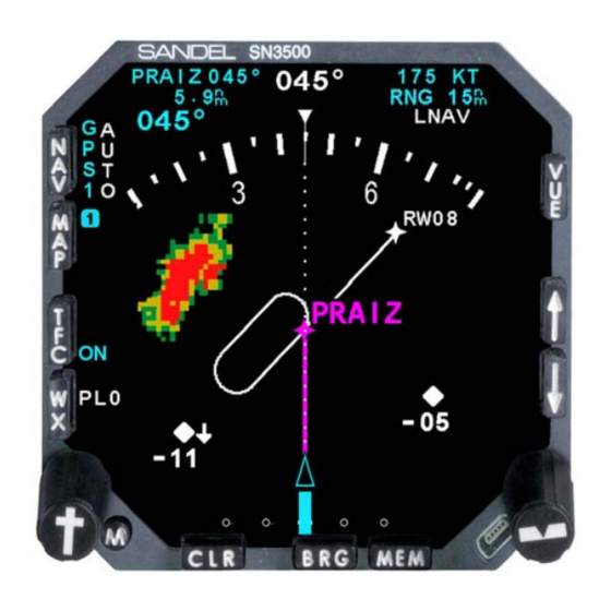
Page 63: Traffic With Moving Map (Figure 8-2)
APPENDIX Traffic with moving map (Figure 8-2) 82005-PG, REV M SANDEL SN3500 PILOT’S GUIDE PAGE 17-13...
Need help?
Do you have a question about the SN3500 and is the answer not in the manual?
Questions and answers