Table of Contents
Advertisement
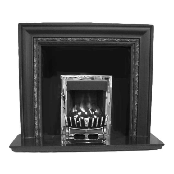
RIVIERA
G C No. 32-170-23
AND
BELVEDERE
G C No. 32-170-24
Cat II
G20 at 20mbar convertible to G31 at 37mbar.
2H3P
For use in GB and IE.
Installation & Servicing Instructions
The Data Badge and Serial Number are located on the left hand side of the base panel.
PLEASE LEAVE THESE INSTRUCTIONS WITH THE USER
Advertisement
Table of Contents

Related Manuals for Robinson Willey RIVIERA


Summary of Contents for Robinson Willey RIVIERA
- Page 1 RIVIERA G C No. 32-170-23 BELVEDERE G C No. 32-170-24 Cat II G20 at 20mbar convertible to G31 at 37mbar. 2H3P For use in GB and IE. Installation & Servicing Instructions The Data Badge and Serial Number are located on the left hand side of the base panel.
- Page 2 This product uses fuel effect pieces containing Refractory Ceramic Fibre (RCF), which are man-made vitreous silicate fibres. Excessive exposure to these materials may cause temporary irritation to eyes, skin and respiratory tract, consequently, it makes sense to take care when handling these articles to ensure that the release of dust is kept to a minimum.
-
Page 3: Table Of Contents
CONTENTS SECTION PAGE INTRODUCTION AND GENERAL INSTALLATION REQUIREMENTS TECHNICAL DATA AVAILABLE FENDERS AVAILABLE TRIMS CONTENTS OF SCREW PACK CONTENTS OF COAL PACK CONDITIONS OF INSTALLATION SITING GENERAL FLUES AND CHIMNEYS Brick Chimney, 178mm diameter (7 inch) Stone or Lined Flue and 125mm diameter (5 inch) Flue 5.2.1 Pre-Cast Flue 5.2.2... -
Page 4: Technical Data
NO COMPONENT OF THIS FIRE IS MANUFACTURED FROM ASBESTOS OR ASBESTOS RELATED PRODUCTS. THE BELVEDERE AND RIVIERA are a range of open fronted inset live coal effect gas fires specially designed for Pre-Cast Flue application and are also suitable for use with Brick Chimneys, twin walled or insulated Metal/Pre-fabricated Flues of 125mm minimum diameter and Flueboxes conforming to the constructional requirements of BS 715. -
Page 5: Available Fenders
2.0 AVAILABLE FENDERS BELVEDERE FENDER AND ASHPAN RIVIERA FENDER AND ASHPAN Both the above are available in black/brass or black/chrome effect... -
Page 6: Available Trims
2.1 AVAILABLE TRIMS BELVEDERE TRIM Available in Black with Brass or Chrome effect insert RIVIERA TRIM Available in Brass or Chrome effect... -
Page 7: Contents Of Screw Pack
3.0 CONTENTS OF SCREW PACK The contents of the screw pack are as follows (refer to Fig 1.): - Description Fixing Cables Cable Adaptors Grub Screws Cable Eyelets Wall Plugs Fire Fixing Screws No 6 Self Tapping Screws Restrictor Gas Inlet Grommet Cable Tensioning Bolts Fig 1. -
Page 8: Conditions Of Installation
5.0 CONDITIONS OF INSTALLATION 5.1 SITING GENERAL This fire is suitable for hearth mounting only on a non-combustible hearth at least 13mm thick and measuring at least 630mm wide by 330mm deep, the periphery of which should preferably be 50mm above the floor level in order to discourage the placing of carpets or rugs over it. -
Page 9: Pre-Cast Flue
5.2.2 PRE-CAST FLUE OF MINIMUM SIZE (Fig. 4) PRE-CAST FLUE INSTALLATION This fire can be installed into a properly constructed pre-cast flue conforming to B.S. 1289 : 1975 or B.S. 1289 : Part 1 : 1986 or B.S. 1289 : Part 2 : 1989 of at least 3 metres effective height and having flueways of at least 198mm by 67mm or equivalent cross-sectional area with no dimension less than 63mm. - Page 10 Fig 5. Fig 6. 4 SPIGOT SCREWS 500.0 244.0 Fig 7. GAS SUPPLY PIPE KNOCK OUTS 100.0...
- Page 11 5.2.4 METAL FLUE BOX/125mm DIAMETER FLUES (Figs. 8 and 9) 125 I/D This fire may be installed in a double walled or insulated metal box built to the requirements of B.S. 715 e.g. Selkirk, Product Code Number 0404805, using our fixing kit G.C.
-
Page 12: Combustible Shelf
SHELF HEIGHT AND SIDE CLEARANCES The fire may be fitted beneath a shelf. depth 250mm 5.3.1 COMBUSTIBLE SHELF A shelf may be fitted above the heater provided that it complies with depth 200mm the dimensions shown in the diagram. No combustible shelf may be fitted below the minimum of 150mm. depth 150mm The minimum clearance to combustible sides must comply with the dimensions in the diagram. - Page 13 6.2.2 Remove the fender mask by removing the two screws. Refer to Fig 11. Fig 11. 6.2.3 Remove the burner tray by removing the two screws. Refer to Fig 12. Fig 12.
-
Page 14: Methods Of Installation
6.3 METHOD OF INSTALLATION There are two methods for securing the fire to the wall which are: Fixing by tension cable. Screwing the fire directly to the wall. It is recommended, where drilling holes in the front face of the fireplace surround is unacceptable or otherwise risky e.g. a marble surround, that fixing by tension cable is employed. -
Page 15: Gas Connection
6.4 GAS CONNECTION NOTE: The appliance must be connected to gas with rigid or semi-rigid tubing, from either the right or left hand side, or by concealed connection (see below). The supply pipe to the fire should be installed so that it is easy to remove the fire from the opening during servicing. -
Page 16: Test For Gas Soundness
Push the supply pipe through the hole just created and connect the isolation elbow removed from the burner assembly. Refer to Fig 19. The end position is shown in Fig 20.The pipe run from the supply line up to the rear opening in the firebox must be kept clear of the area which will be taken by the box when it is installed. -
Page 17: Commissioning
7.0 COMMISSIONING 7.1 INSTALL FUEL EFFECT COMPONENTS The fuel effect components comprise: Rear Coal Two Side Cheeks Coal Bed Seven Rectangular Coals The Coal Bed and the loose coals are illustrated in Fig 2. The fire is supplied with the rear brick effect panel already fitted as illustrated in Fig 11. - Page 18 Fit the trim to the fire by hooking it over the top of the firebox top. Refer to Fig 25. Fig 25. TRIM MAGNET The bottom of the trim is held in place with magnets. Push the bottom of the trim at each side onto the magnets. NOTE: If the magnet on either side came away with the trim on removal, transfer it back to the “bump”...
-
Page 19: Check Gas Pressure
Place 4 rectangular coals onto the base coal with their decorative faces visible. They should have the front end touching the back of the fender or inline with it. Refer to Fig Fig 28. Place the 3 remaining rectangular coals resting in the `V’ s just created and leaning back to rest on the rear coal. -
Page 20: Test For Spillage
7.3 TEST FOR SPILLAGE A test for spillage must be made before the installed fire is left with the user. This is carried out in the following manner. Light the fire and leave at HIGH rate. Close all the doors and windows in the room and after the fire has been alight for five minutes insert a lighted smoke match into the notch in the canopy in a horizontal direction with the tip 50 mm inside the canopy (See Fig. -
Page 21: Instruct User
8.0 INSTRUCT USER Refer to Users Instructions Make sure the user understands the following: (a) How to light and operate the fire. (b) The fire can be lit with a match or taper in the event of failure of the spark ignition. Demonstrate the removal and replacement of the coals. -
Page 22: Pilot Assembly
9.4 PILOT ASSEMBLY The pilot is an atmosphere sensing device and must be replaced as a complete unit. Repair must not be undertaken. NOTE: If the fire keeps going out or exhibits signs of nuisance shut off, check the operation of the pilot as follows:- Check the pilot lint trap for blockage. -
Page 23: Hints On Fault Finding
10.0 HINTS ON FAULT FINDING The following are possible fault conditions. Check the items mentioned and repair or replace parts as necessary. The list is not exhaustive but a fair outline of possible faults. No Spark Check spark by manually operating the spark generator. Check the spark gap and electrode alignment (see Fig 31). -
Page 24: Notepad
11.0 NOTEPAD... - Page 25 11.0 NOTEPAD...
- Page 26 822329 Main Burner Injector (Propane Gas) 990454 Aeration Plate (Propane Gas) 822328 Trim Magnet 822326 Gas Inlet Grommet 989510 Issue 3 - January 2001 ROBINSON WILLEY LIMITED Mill Lane, Old Swan, Liverpool. L13 4AJ. England. Telephone: 0151-228-9111 Fax: 0151-228-6661 www.robinson-willey.co.uk...
- Page 27 AMMENDMENT HISTORY 11/01/2001 Page 8 text and Fig 3 dimensions Page 9 text and Fig 4 dimensions Issue upped to 3...
Need help?
Do you have a question about the RIVIERA and is the answer not in the manual?
Questions and answers