Table of Contents
Advertisement
Please note that some of the contact details on
this PDF document may not be current.
Please use the following details if you need to
Email: customer.services@gdcgroup.co.uk
The Help Centre section of this website also features a wide range
of information which may be of use to you and is available 24
hours a day. It includes:
• Manuals and guides downloads
• Servicing
• Where to buy our products
• Literature downloads
A division of GDC Group Ltd
Millbrook House Grange Drive Hedge End Southampton SO30 2DF
www.robinsonwilley.co.uk
Contact Details
contact us:
Telephone: 0844 879 3588
www.robinsonwilley.co.uk/help
Registered No: 1313016 England
VAT GB 287 1315 50004
EEE Producer Registration Number –
WEE/GE0057TS
Paper from sustainable sources
Advertisement
Table of Contents

Related Manuals for Robinson Willey firecharm lf


Summary of Contents for Robinson Willey firecharm lf
- Page 1 Contact Details Please note that some of the contact details on this PDF document may not be current. Please use the following details if you need to contact us: Telephone: 0844 879 3588 Email: customer.services@gdcgroup.co.uk The Help Centre section of this website also features a wide range of information which may be of use to you and is available 24 hours a day. It includes: • Manuals and guides downloads • Servicing • Where to buy our products • Literature downloads www.robinsonwilley.co.uk/help A division of GDC Group Ltd Registered No: 1313016 England VAT GB 287 1315 50004 Millbrook House Grange Drive Hedge End Southampton SO30 2DF EEE Producer Registration Number –...
- Page 2 987618 Issue 5 FIRECHARM LF ELECTRONIC RADIANT/CONVECTOR GAS FIRE BRONZE (G.C. No. 32 689 32) BLACK (G.C. No. 32 689 33) Installation and Servicing Instructions THIS APPLIANCE IS FOR USE WITH NATURAL GAS ONLY IT MUST NOT BE USED WITH ANY OTHER TYPE OF GAS...
- Page 3 Robinson Willey Firecharm and Sahara Live Fuel Effect Gas Fires The efficiency of this appliance has been measured as specified in BS 7977-1:2002 and the result is 79.4%. The gross calorific value of the fuel has been used for this efficiency calculation. The test data from which it has been calculated has been certified by Notified Body No.0087.
-
Page 4: Gas Safety (Installation And Use) Regulations
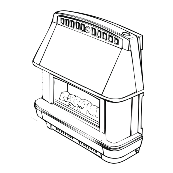
INTRODUCTION The FIRECHARM is a glass fronted radiant/convector fire with live coal effect. The outer case is finished in either black or bronze. The control and burner systems are designed to give varying decorative flames at different settings. Ignition is by battery spark generator operated by turning and pressing the control knob. -
Page 5: Specifications
SPECIFICATIONS 1.0 TECHNICAL DATA Fig. 1A 1.1 OVERALL DIMENSIONS (mm) Height 650mm Width Depth Height to top of flue spigot 1.2 HEAT INPUT/OUTPUT (GROSS) Maximum input 5.57kW 19000 Btu/h Maximum output 4.4kW 15012 Btu/h Minimum input 1.55kW 5289 Btu/h Minimum output 0.83kW 2822 Btu/h Setting Pressure (Full on) -
Page 6: Site Requirements
SITE REQUIREMENTS 2.0 SITE REQUIREMENTS 2.1 THE FIREPLACE AND SURROUND The fireplace must be of non-combustible material having an opening size to the dimensions shown in Fig. 3A for Hearth Mounting and Fig 3B for Wall Mounting respectively. It is IMPORTANT that there is no combustible material or cladding in the vertical flat area shown in dotted lines in Figs. - Page 7 SITE REQUIREMENTS HEARTH MOUNTING (Fig. 3A) Fig. 3A The hearth must be non-combustible material at least 13mm ( in) thick and measuring at least 670mm in) wide by 300mm (12in) deep with the fireplace 400mm Vertical Flat Area opening central. Its top surface should preferably be 300/457mm 50mm (2in) above the floor level to discourage placing of rugs or carpets over it.
- Page 8 SITE REQUIREMENTS 2.2 BRICK CHIMNEY 228mm x 228mm (9in x 9in) Minimum A chimney previously used to burn solid fuel must be of 50mm swept prior to installation. Minimum of 13mm The chimney must be inspected to ensure that:- It serves only one fireplace. It is properly sealed so that combustion products do not escape from the flueways into the room.
- Page 9 SITE REQUIREMENTS 2.3 PRE-CAST FLUE OF MINIMUM CROSS SECTION 198mm x 67mm (7 in x 2 in ) (Fig. 5) Fig. 5 The fire is suitable for installation into a properly constructed pre-cast flue conforming to the standards listed on page 2, item 6, of at least 3m (10ft) effective height and having flueways of at least 198mm x 67mm in x 2 in) or equivalent cross sectional area with...
-
Page 10: Installation
INSTALLATION 3.0 INSTALLATION 3.1 UNPACK THE FIRE AND ACCESSORIES Remove the top fitment. Lift the carton clear of the fire pack. The fire is packed fully assembled except for:- Closure plate - in the rear cardboard fitment. (ii) The accessory pack, in the LH base fitment contains:- Spigot Spigot Restrictor... -
Page 11: Spigot Restrictor
INSTALLATION 3.2.1 When Hearth Mounting Fit the closure plate centrally across the fireplace opening and seal all four edges 3.2.2 When Wall Mounting Ensure that the top of the spigot opening is at least 595mm above the finished floor level and at least 13mm below the top edge of the fireplace opening and that the air relief opening is unobstructed. - Page 12 INSTALLATION 3.6 FLUE SPIGOT RESTRICTOR (Fig. 8) Fig. 9 Standard 228mm x 228mm (9in x 9in) brick chimney. The flue spigot restrictor must not be Backplate of fire used if the chimney height is less than 4.3m (14ft) or if poor draught is suspected. If over 4.3m (14ft) in height with good draught, the flue spigot 590mm restrictor (Fig.
-
Page 13: Connect To Gas Supply
INSTALLATION 4.0 CONNECT TO GAS SUPPLY NOTE: The appliance must be connected to gas with rigid or semi rigid tubing. (ii) The fire is fitted with an ‘isolating inlet elbow’ for servicing. (iii) Remove tray for access. 4.1 MAKE GAS CONNECTION The gas inlet is suitable for right hand, left hand or concealed connection. -
Page 14: Test For Spillage
INSTALLATION 5.0 FIT REMAINING COMPONENTS 5.1 REFIT THE BURNER TRAY 5.2 FIT THE COAL BED Fit the coal bed into the firebox as shown in Fig. 11 ensuring it is located behind the metal front rail. 5.3 FIT THE GLASS DOOR Do this by inserting the top into the top clip of the firebox and guiding the lower holes over the firebox studs. -
Page 15: Instruct User
INSTALLATION 6.1 CHECK IGNITION Check that ignition of the pilot and the cross-lighting to Fig. 12 the main burner is satisfactory. N.B. The spark gap between the electrode and thermocouple tip should be between 3.5 and 5.5mm 3.0 - 5.0mm (See Fig. -
Page 16: Pilot Assembly
8.1 REMOVAL OF OUTER COMPONENTS. Remove the front panel by lifting upward and pulling forward. Pull out the control knob. Remove 4 screws 2 either side securing the outer case and lift the case away from the fire. Remove the glass door by withdrawing the 2 dome nuts securing it then removing the door bottom end first. -
Page 17: Short List Of Parts
Gas Tap Assembly (c/w switch) 991762 Control Knob Robinson Willey GDC Group Ltd, Millbrook House, Grange Drive, Hedge End, Southampton, SO30 2DF. Telephone: 0844 879 35 88 E-mail: info@robinsonwilley.co.uk website: www.robinsonwilley.co.uk Robinson Willey is a Trading Division of the GDC Group Ltd...
Need help?
Do you have a question about the firecharm lf and is the answer not in the manual?
Questions and answers