Table of Contents
Advertisement
Advertisement
Table of Contents

Summary of Contents for E-Tech DrivE-Tech 015
- Page 1 Installing and operating manual DrivE-Tech 015, 030, 022, 040, 055, 075, 110, 150...
-
Page 2: Table Of Contents
Index 1. DrivE-Tech Introduction ..............................3 2. Safety Instructions ................................3 3. Technical Characteristics ..............................4 3.1 Weight and dimensions ................................4 4. Electric wiring ..................................5 4.1 Protections ....................................9 4.2 Electromagnetic compliance ..............................9 4.3 Installation with long motor cables ............................9 5. -
Page 3: Drive-Tech Introduction
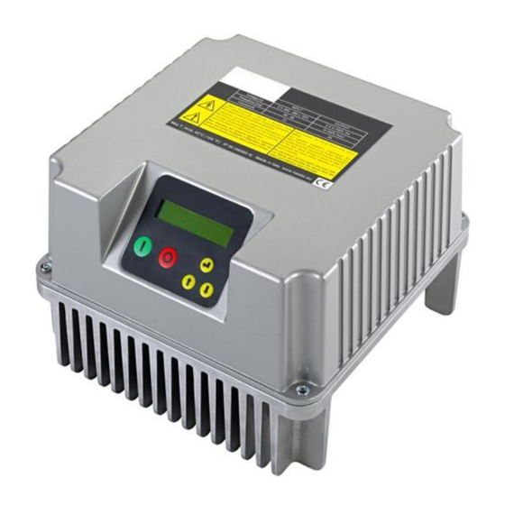
1. DrivE-Tech Introduction DrivE-Tech is a variable frequency drive designed to control and protect pumping systems by varying the output frequency to the pump. DrivE-Tech can be applied to both new and existing pumping systems, and provides: energy and cost savings ... -
Page 4: Technical Characteristics
Typical P2 motor Vout current Model current [V] AC [KW] [HP] 1 x Vin DrivE-Tech 015 1 x 230 VAC 3 x Vin 1 x Vin DrivE-Tech 030 1 x 230 VAC 3 x Vin DrivE-Tech 022 3 x 380-460 VAC... -
Page 5: Electric Wiring
4. Electric wiring Power board DrivE-Tech 015,030 Power supply: Output: 230 V AC auxiliary fans (wall LINE: L1, L2, earth 3 ph motor: mounting kit) It is recommended to use cable earth ,U,V,W, FAN: F1, F2 lugs 1 ph motor: earth, U (running), V (common) It is recommended to use cable lugs. - Page 6 Power board DrivE-Tech 022,040 Power supply: Motor output: 12 V dc auxiliary fan (wall mounting kit) : LINE: GND , L1, L2, L3, MOTOR: U, V, W, GND 0VE, + VE It is recommended to use cable It is recommended to use cable WARNING: respect the polarity.
- Page 7 Power board DrivE-Tech 055,075,110,150 Power supply: Motor output: 12 V dc auxiliary fans (wall mounting kit) LINE: L1, L2, L3, GND MOTOR: U, V, W, GND VENT: +, - It is recommended to use cable It is recommended to use cable WARNING: respect the polarity.
- Page 8 Control board Analog inputs (10 or 15 Vdc): Digital outputs: RS485: 1. AN1: 4-20 mA: sensor 1 motor run signal: S+ 2. AN2: 4-20 mA: sensor 2 S- NO1, COM1: closed contact with motor 3. AN3: 4-20 mA / 0 - 10 Vdc ...
-
Page 9: Protections
4.1 Protections The protections required upstream each DrivE-Techs depends on the type of installation, and local regulations. We recommend to use overload protection with the characteristic curve of type C and type B circuit breaker, sensitive to both AC and DC current. 4.2 Electromagnetic compliance To ensure electromagnetic compatibility (EMC) of the system, it is necessary to apply the following measures: ... -
Page 10: Drive-Tech Installation
DrivE-Tech can be installed directly on the fan cover of the motor or mounted on the wall. Motor mounting kit In this application DrivE-Tech is cooled by the motor fan. Motor kit (available upon request) allows a solid coupling of the two units and it is composed of: DrivE-Tech 015,030,022,040 DrivE-Tech 055,075,110,150 ... - Page 11 Wall mounting kit In this application DrivE-Tech is cooled independently by its auxiliary cooling fan integrated in the radiator. Wall-mounted kit is composed of: DrivE-Tech 015,030,022,040 DrivE-Tech 055,075,110 n.° 1 auxiliary fan 230V AC (DrivE-Tech n.° 2 12 V DC fans.
-
Page 12: Drive-Tech Installation For Constant Pressure Control
5. DrivE-Tech Installation for constant pressure control DrivE-Tech controls the pump speed to maintain constant pressure at a set point independent of the water demand in the system. A basic schematic is shown below: 1: pump DrivE-Tech 2: check valve 3: pressure tank 4: valve 5: valve... -
Page 13: Drive-Tech Use And Programming
6. DrivE-Tech Use and Programming DrivE-Tech software is extremely simple to use, but allows a wide variety of parameters to be set for ideal system calibration. Setting Parameters are organized in 2 levels: 1: Installer level A password is required for this level; these parameters are adjustable by trained professionals Default password: From the menu a different password can be set up. - Page 14 XXXXXX Unit Unit XXXXX threephase Type of motor connected (DrivE-Tech 015,030) Motor type singlephase/threephase Rated current of the motor per it’s nameplate indication increased by Rated motor Amp. 10%. The voltage drop caused by the inverter leads to higher input current than nominal.
-
Page 15: Initial View
6.3 Initial view When first powering the DrivE-Tech, the display shows : release of display software (LCD = X.XX) and the release of inverter software (INV = X.XX) as shown below: LCD = X.XX INV = X.XX The following End User messages are displayed by pushing the scroll buttons: p is the pressure value read by the pressure transducer. -
Page 16: Menu View
Inv: ON Mot: OFF DrivE-Tech is powered but motor is not running (i.e. motor/pump was stopped due to minimum frequency being reached) Inv: OFF Mot: OFF DrivE-Tech is not powered If COMBO function is activated, the DrivE-Tech address is placed close to indication “Inv”. 6.4 Menu view Pressing ENTER when you are in [MENU’... - Page 17 parameter desciption F. scale sensor Sensor full scale. p = XX.X [bar] Sensor minimum value. Min value sensor p = XX.X [bar] Maximum value allowed in the system. If the readen value goes over this value, ...
- Page 18 parameter desciption To ensure proper operation of pressure control is recommended to place the sensor near the pump. To compensate the pressure loss in the pipes (proportional to flow) it is possible to vary the pressure set in a linear relation with respect to frequency.
- Page 19 parameter desciption stop the pump. This value represents the value drop Delta control below the set value required to restart the pump during control ramp. p = XX.X [bar] press. Set value Delta control Control ramp Stop delay Freq.min.control Min mot.
- Page 20 parameter desciption delay time with which the pumps DOL Start delay AUX start after the variable speed pump has reached the maximum frequency and t = XX [s] the readen value has fallen below set value – delta control. Function to enable multiple DrivE-Tech’s to work in parallel as described in the technical appendix (see the relevant...
-
Page 21: Advanced Parameters
parameter desciption By selecting N.C. (normally closed) DrivE-Tech runs the motor if the digital input 3 is closed; motor will be stopped if the digital input 3 is opened. By selecting N.A. (normally open) DrivE-Tech runs the motor if the digital input 4 is open;... - Page 22 Minimum frequency of the motor. Note: depends on the selected pump Min motor freq. type; for submersible pumps with water filled motors, is not advisable to set minimum frequency lower than 30 Hz in order to protect the integrity of the f = XXX [Hz] thrust bearings.
- Page 23 If ON is selected, after a lack of voltage, DrivE-Tech returns to its normal Autorestart status; if DrivE-Tech was powering the pump before the voltage drop, it resumes powering the pump automatically. ON/OFF Warning, review the advice in chapter 1. Pump periodic autorun after XX hours of inactivity.
-
Page 24: Protections And Alarms
7. Protections and alarms Anytime a protection occurs a blinking message is displayed together with an audible alarm; on STATUS in the initial view, the protection is displayed; by pressing the STOP button. Only from this position (STATUS) in the initial view is it possible to try to reset the alarm;... -
Page 25: Auxiliary Pumps During Constant Pressure Control
value accepted by the system. (i.e. broken pipe, open pressure relief valve, etc.) Check the min alarm value setting. Increase the ramp-up time The current drawn by the load exceeds the Make sure that the load current is at least capacity of DrivE-Tech. -
Page 26: Dol Pumps
In this method, DOL pumps are not started and stopped smoothly with the corresponding increase in energy consumption and mechanical wear (startup current). Also note that DOL pumps are not protected by DrivE-Tech. A second method of sharing water demand (named COMBO mode) consists of using additional pumps in parallel (up to 8), with each one driven by a DrivE-Tech. -
Page 27: Combo Function
P1+P2 P1@f min Q=0 If two pumps are connected in parallel, the first driven by DrivE-Tech and the second with a DOL connection, it is necessary makes sure that the value “delta control” will be sufficiently high to ensure the first pump, once the DOL pump is switched on, will reach a frequency higher than its minimum frequency value. - Page 28 As a further help, you can connect another two DOL pumps to the DrivE-Tech Master to cover additional water demand; they will be operated only when all the COMBO pumps are already in operation. RS485 serial connection DrivE-Tech’s communication is made through a private protocol using the RS485 port. Each DrivE-Tech must be connected to each other by using a tripolar cable (0,5 mm ) wired on S+,S-,G pins on control board.
-
Page 29: Trouble-Shooting Chart
DrivE-Tech’s address in parallel operation. Address 00 : DrivE-Tech master Function to allow alternating between the DrivE-Techs connected in parallel in Alternance order to allow equal use of each pump in the group; in this way Master will reorganize the starting priority of the pumps by checking the life of each of them. ON/OFF Delay time with which the slaves start after the variable speed pump has reached Start delay AUX... - Page 30 to wait at least 1 minute before restarting. When performing sensor test operation, Check that the sensor cable is properly connected to the sensor device SENSOR OFF alarm occurs and to the DrivE-Tech. Make sure that the sensor and its cable are not damaged. ...
-
Page 31: Technical Assistance
10. Technical Assistance For more technical information contact the authorized reseller providing the following information. The solution to the problem will be found faster and easier if full information is provided. Model/Serial Code LCD version (shown when DrivE-Tech is power INV version (shown when DrivE-Tech is supplied) power supplied) -
Page 32: Declaration Of Conformity
Direttiva Macchine 2006/42/CE Direttiva EMC 2004/108/CE DrivE-Tech 015,030,022,040,055,075,110,150 è un dispositivo elettronico da collegare ad altre macchine elettriche con le quali viene a formare singole unità. E’ necessario, pertanto, che la messa in servizio di questa unità (corredata di tutti i suoi organi ausiliari) sia effettuata da personale qualificato. - Page 33 NOTE manDrivE-Tech_eng_10.docx...
Need help?
Do you have a question about the DrivE-Tech 015 and is the answer not in the manual?
Questions and answers