Teltonika RUT950 User Manual
Lte router
Hide thumbs
Also See for RUT950:
- User manual (172 pages) ,
- Quick start manual (9 pages) ,
- Quick start manual (2 pages)
Table of Contents
Advertisement
Quick Links
Advertisement
Table of Contents

Related Manuals for Teltonika RUT950


Summary of Contents for Teltonika RUT950
- Page 1 USER MANUAL RUT950 LTE Router...
-
Page 2: Legal Notice
Copyright © 2015 TELTONIKA Ltd. All rights reserved. Reproduction, transfer, distribution or storage of part or all of the contents in this document in any form without the prior written permission of TELTONIKA Ltd is prohibited. The manufacturer reserves the right to modify the product and manual for the purpose of technical improvement without prior notice. -
Page 3: Table Of Contents
Table of Contents Legal notice ................................2 Attention.................................. 2 SAFETY INFORMATION ............................8 FCC Safety Information ............................9 Canada, Industry Canada (IC) Notices ......................... 9 Radio Frequency (RF) Exposure Information ....................... 9 Canada, avis d’Industry Canada (IC) ........................9 Déclaration d’exposition aux radiations ......................9 Device connection ............................. - Page 4 6.6.2 Active IP-Routes ..........................32 6.6.3 Active IPv6-Routes ........................... 33 Graphs ..............................33 6.7.1 Mobile Signal Strength ........................33 6.7.2 Realtime Load ..........................34 6.7.3 Realtime Traffic ..........................35 6.7.4 Realtime Wireless ..........................37 6.7.5 Realtime Connections ........................38 Mobile Traffic ............................39 Speed Test ..............................
- Page 5 7.6.2 DMZ ..............................70 7.6.3 Port Forwarding ..........................70 7.6.4 Traffic Rules............................73 7.6.5 Custom Rules ........................... 77 7.6.6 DDOS Prevention ..........................77 7.6.7 Port Scan Prevention ........................80 Routing ..............................80 7.7.1 Static Routes ............................ 80 7.7.2 Dynamic Routes ..........................81 Load Balancing ............................
- Page 6 SNMP ..............................114 9.8.1 SNMP Settings ..........................115 9.8.2 TRAP Settings ..........................116 SMS Gateway ............................116 9.9.1 Post/Get Configuration ........................116 9.9.2 Email to SMS ..........................119 9.9.3 Scheduled Messages ........................119 9.9.4 Auto Reply Configuration ....................... 120 9.9.5 SMS Forwarding ..........................
- Page 7 10.3.3 Backup ............................145 10.3.4 Diagnostics ............................. 147 10.3.5 MAC Clone ............................. 148 10.3.6 Overview ............................148 10.3.7 Monitoring ............................. 149 10.4 User scripts ............................149 10.5 Restore point ............................. 150 10.5.1 Restore point create ........................150 10.5.2 Restore point load ......................... 150 10.6 Firmware ............................
-
Page 8: Safety Information
SAFETY INFORMATION In this document you will be introduced on how to use a RUT950 router safely. We suggest you to adhere to the following recommendations in order to avoid personal injuries and or property damage. You have to be familiar with the safety requirements before using the device! To avoid burning and voltage caused traumas, of the personnel working with the device, please follow these safety requirements. -
Page 9: Fcc Safety Information
FCC Safety Information To maintain compliance with FCC’s RF exposure guidelines, this equipment should be installed and operated with minimum distance 20cm between the radiator and your body. Use on the supplied antenna. This device and its antenna(s) must not be co-located or operating in conjunction with any other antenna or transmitter Any changes or modifications not expressly approved by the party responsible for compliance could void the user’s authority to operate the equipment. -
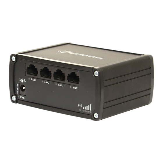
Page 10: Device Connection
Device connection... -
Page 11: Introduction
1 Introduction Thank you for purchasing a RUT950 LTE router! RUT950 is part of the RUT9xx series of compact mobile routers with high speed wireless and Ethernet connections. This router is ideal for people who‘d like to share their internet on the go, as it is not restricted by a cumbersome cable connection. -
Page 12: Applications
2.5 Applications... -
Page 13: Setting Up Your Router
3 Setting up your router 3.1 Installation After you unpack the box, follow the steps, documented below, in order to properly connect the device. For better Wi-Fi performance, put the device in clearly visible spot, as obstacles such as walls and door hinder the signal. 1. -
Page 14: Hardware Installation
Red lit and blinking rapidly while data is being transferred: connected 2G with data session; Yellow lit and blinking rapidly while data is being transferred: connected 3G with data session; Green lit and blinking rapidly while data is being transferred: connected 4G with data session; 3.1.3 Hardware installation 1. - Page 15 4. Then right click on your wireless device that you use to Click “View network connections” connect to other access points (It is the one with the name “Wireless Network Connection” and has signal bars on its icon). 5. Select Internet Protocol Version 4 (TCP/IPv4) and then click 6.
- Page 16 7. If you choose to configure manually here’s what you have to do: First select an IP address. Due to the stock settings that your router has arrived in you can only enter an IP in the form of 192.168.1.XXX , where XXX is a number in the range of 2-254 (192.168.1.2 , 192.168.1.254 , 192.168.1.155 and so on…...
- Page 17 Right click on the Wireless network icon and select Connect / Disconnect. A list should pop up with all available wireless networks. Select “Teltonika” and click connect. Then we launch our favorite browser and enter the routers IP into the address field: Press enter.
-
Page 18: Operation Modes
4 Operation Modes The RUT9xx series router supports various operation modes. It can be connected to the internet (WAN) via mobile, standard Ethernet cable or via a wireless network. When connecting to the internet, you may also backup your main WAN connection with one or two backup connections. Any interface can act like backup if configured so. At first router uses its main WAN connection, if it is lost then router tries to connect via backup with higher priority and if that fails too, router tries the second backup option. -
Page 19: Powering The Device From Higher Voltage
5.1 Powering the device from higher voltage If you decide not to use our standard 9 VDC wall adapters and want to power the device from higher voltage (15 – 30 VDC) please make sure that you choose power supply of high quality. Some power supplies can produce voltage peaks significantly higher than the declared output voltage, especially during connecting and disconnecting them. -
Page 20: Status
6 Status The status section contains various information, like current IP addresses of various network interfaces; the state of the routers memory; firmware version; DHCP leases; associated wireless stations; graphs indicating load, traffic, etc.; and much more. 6.1 Overview Overview section contains various information summaries. -
Page 21: System Information
Teltonika-RUT950.com Indicates how router will be seen by other devices on the network. Can be changed in System -> Administration. 3. Router Model Teltonika RUT950 LTE Routers model. 4. Firmware RUT9XX_R_00.02.345 Shows the version of the firmware that is currently loaded in the router. -
Page 22: Network Information
1. Free 79972 kB / 126556 kB The amount of memory that is completely free. Should this rapidly (63%) decrease or get close to 0, it would indicate that the router is running out of memory, which could cause crashes and unexpected reboots. 2. - Page 23 RSRP -119 dBm Indicates the Reference Signal Received Power RSRQ -11 dBm Indicates the Reference Signal Received Quality SINR -1.2 dBm Indicates the Signal to Interference plus Noise Ratio Operator OMNITEL LT Operator's name of the connected GSM network Operator state Registered (home) GSM network's status Connection type...
- Page 24 WAN MAC 00:1E:42:00:00:01 MAC (Media Access Control) address used for communication in a Ethernet WAN (Wide Area Network) Netmask* 255.255.255.0 Specifies a mask used to define how large the WAN network is Gateway* 192.168.99.254 Indicates the default gateway, an address where traffic destined for the internet is routed to.
- Page 25 2. IP address 192.168.99.120 Each lease declaration includes a single IP address that has been leased to the client 3. LAN name LAN instance name 4. MAC address D4:85:64:65:2B:D4 The MAC (Media Access Control) address of the network interface on which the lease will be used.
- Page 26 some local AP. 5. Encryption no encryption The AP, to which the router is connected to, dictates the type of encryption. 6. Wireless MAC 00:1E:42:10:80:22 The MAC address of the access points radio. 7. Signal Quality The quality between routers radio and some other device that is connecting to the router.
- Page 27 point. 5. Encryption No Encryption The type of encryption that the router will use to authenticate, establish and maintain a connection. 6. Wireless MAC 00:1E:42:00:00:03 MAC address of your wireless radio. 7. Signal Quality The quality between routers radio and some other device that is connecting to the router.
- Page 28 6.3.1.7 OpenVPN Server Display OpenVPN connection information on server side. Field Name Sample Value Explanation 1. Enabled Yes/No OpenVPN status 2. Status Connected Connection status 2. Type Server A type of OpenVPN instance that has been created 3. IP 10.0.0.1 Remote virtual network's IP address 4.
- Page 29 Field Name Sample Value Explanation 1. Status Enabled VRRP status 2. Virtual IP 192.168.1.253 Virtual IP address(- es) for LAN’s VRRP (Virtual Router Redundancy Protocol ) cluster 3. Priority Router with highest priority value on the same VRRP (Virtual Router Redundancy Protocol) cluster will act as a master, range [1 - 255] 4.
- Page 30 Field Name Sample Value Explanation 1. Type SSH; HTTP; HTTPS Type of connection protocol 2. Status Disabled/Enabled Connection status 3. Port 22; 80; 443 Connection port used 4. Active 0(0.00B);1(9.26 KB); Count of active connections and amount of data transmitted in KB Connections 6(558.12 KB) **-Exclusive to other Modes with Slave.
-
Page 31: Device Information
4. Authentications Failed; Succeed Status of authentication attempt Status 6.4 Device information The page displays factory information that was written into the device during manufacturing process. Field Name Sample Value Explanation Serial number 02345678 Serial number of the device Product code RUT950101010 Product code of the device Batch number... -
Page 32: Routes
6.6 Routes The page displays ARP table and active IP routes of the device. 6.6.1 Show the routers active ARP table. An ARP table contains recently cached MAC addresses of every immediate device that was communicating with the router. Field Name Sample Value Explanation 1. -
Page 33: Active Ipv6-Routes
Field Name Sample Value Explanation 1. Network Interface to be used to transmit TCP/IP packets through 2. Target 192.168.99.0/24 Indicates where a TCP/IP packet, with a specific IP address, should be directed 3. IP Gateway 0.0.0.0 Indicates through which gateway a TCP/IP packet should be directed 4. -
Page 34: Realtime Load
Field Name Sample Value Explanation 1. Connection type 3G (WCDMA) Type of mobile connection used 2. Signal -72 dBm Current signal strength value 3. Average -72.0 dBm Average signal strength value 4. Peak -72 dBm Peak signal strength value 6.7.2 Realtime Load This tri-graph illustrates average CPU load values in real time. -
Page 35: Realtime Traffic
Field Name Sample Value Explanation 1. 1/5/15 Minutes 0.83 Time interval for load averaging, colour of the diagram Load 2. Average 0.86 Average CPU load value over time interval (1/5/15 Minute) 3. Peak 1.50 Peak CPU load value of the time interval 6.7.3 Realtime Traffic This graph illustrates average system inbound and outbound traffic over the course of ~3 minutes;... - Page 36 Field Name Explanation 1. Bridge Cumulative graph, which encompasses wired Ethernet LAN and the wireless network. 2. LAN Graphs the total traffic that passes through both LAN network interfaces. 3. WAN (Wired) Graphs the amount of traffic which passed through the current active WAN connection. 4.
-
Page 37: Realtime Wireless
6.7.4 Realtime Wireless Display the wireless radio signal, signal noise and theoretical maximum channel permeability. Average and peak signal levels are displayed. -
Page 38: Realtime Connections
6.7.5 Realtime Connections Displays currently active network connections with the information about network, protocol, source and destination addresses, transfer speed. -
Page 39: Mobile Traffic
6.8 Mobile Traffic Displays mobile connection data sent and received in KB of this day, week, Month. By default mobile traffic usage logging is disabled. To use this functionality is needed to enable it. Field Name Sample Value Explanation 1. Enable Enable/Disable Make a functionality active/inactive 2. -
Page 40: Events Log
6.10 Events Log Event log displays such actions as: login, reboot, firmware flashing and reset. 6.10.1 All Events Display all router events, their types and time of occurrence. -
Page 41: System Events
6.10.2 System Events Display all system events, their type and time of occurrence. Events include authentication or reboot requests, incoming and outgoing SMS and calls, Mails, Configuration changes, DHCP events. -
Page 42: Network Events
6.10.3 Network Events Display information about recent network events like connection status change, lease status change, network type or operator change. -
Page 43: Events Reporting
6.10.4 Events Reporting Allow to view, enable/disable or modify created rules for events reporting. 6.10.4.1 Events Reporting Configuration Allow to review created rules details and modify them, so after event occurrence, messages or emails are sent to specified address or phone numbers with information about the event. -
Page 44: Reporting Configuration
Field Name Sample Value Explanation 1. Enable Enable/Disable Make a rule active/inactive 2. Event type Reboot Select event type about which occurrence information will be sent 3. Event subtype After unexpected shut Specify event subtype to activate the rule down 4. - Page 45 6.10.5.1 Events Log Report Configuration Allow to change the configuration of periodic events reporting to email or FTP. FTP: Field Name Sample Value Explanation Enable Enable/Disable Make a rule active/inactive Events log System Events log for which the rule is applied Transfer type Events log file transfer type: Email/FTP Compress file...
- Page 46 Field Name Sample Value Explanation Enable Enable/Disable Make a rule active/inactive Events log System Event log for which the rule is applied Transfer type Email Events log file transfer type: Email/FTP Compress file Enable Enable/disable compress events log file using gzip Subject Subject Subject of an email...
-
Page 47: Network
7 Network 7.1 Mobile 7.1.1 General 7.1.1.1 Mobile configuration Here you can configure mobile settings which are used when connecting to your local 3G/LTE network. Field Name Sample value Explanation Connection PPP / NDIS PPP mode uses dialling number to establish data connection. type NDIS mode (default) does not use dialling and PPP protocol to establish data connection it is usually faster than PPP mode. - Page 48 Service mode 2G only, 2G preferred, Your network preference. If your local mobile network supports 2G, 3G only, 3G preferred, 3G and 4G (LTE) you can specify to which network you wish to 4G (LTE) only, 4G (LTE) connect. E.g.: if you choose 2G, the router will connect to a 2G preferred or automatic.
- Page 49 7.1.1.2 Mobile Data On Demand Field name Possible values Explanation 1. Enable Enable/Disable Mobile Data On Demand function enables you to keep mobile data connection on only when it's in use 2. No data 1-99999999 A mobile data connection will be terminated if no data is transferred during the timeout(sec) timeout period 7.1.1.3 Force LTE network...
-
Page 50: Sim Management
Perform a SIM card switch when network is denied 10. On data connection Enable/Disable Perform a SIM card switch when data connection fails fail * Your carrier's data usage accounting may differ. Teltonika is not liable should any accounting discrepancies occur. -
Page 51: Network Operators
7.1.3 Network Operators 7.1.3.1 Network Operators This function lets you Scan, Select and enter manual Network Operator to which router should connect. Function will provide great utility when router is in Roaming conditions. Operator is selected only for the active SIM card. In order to specify operator for the other SIM card it must first be selected as primary SIM in “SIM Management”. -
Page 52: Mobile Data Limit
3. Period Month/Week/Day Period for which mobile data limiting should apply 4. Start day/ Start hour A starting time for mobile data limiting period * Your carrier's data usage accounting may differ. Teltonika is not liable should any accounting discrepancies occur. -
Page 53: Sim Idle Protection
+37012345678 A phone number to send warning SMS message to, e.g. +37012345678 * Your carrier's data usage accounting may differ. Teltonika is not liable should any accounting discrepancies occur. 7.1.5 SIM Idle protection Some operators block user SIM cards after period of inactivity. This function enables router to periodically switch to secondary SIM card and establish data connection with mobile network in order to prevent SIM card blocking. -
Page 54: Wan
7.1.5.2 Test Tests the functioning of idle protection with your parameters entered at settings tab. Field Name Sample value Explanation 1. SIM SIM1 / SIM2 Displays SIM number 2. SIM state OK (inserted) Displays status of the SIM card 3. Host IP 8.8.8.8 Displays the IP of the Host 4. -
Page 55: Common Configuration
7.2.2 Common configuration Common configuration allows you to configure your TCP/IP settings for the wan network. You can switch between the Static, DHCP or PPPoE protocol by selecting the protocol that you want to use and then pressing Switch Protocol. 7.2.2.1 General Setup 7.2.2.1.1 Static: This is the configuration setup for when you select the static protocol. - Page 56 7.2.2.1.2 DHCP: When you select the DHCP protocol you can use it as is, because most networks will not require any additional advanced configuration. 7.2.2.1.3 PPPoE This protocol is mainly used by DSL providers: This is the configuration setup for when you select PPPoE protocol. Filed name Sample Explanation...
- Page 57 7.2.2.2.1 Static Field name Sample value Explanation 1. Disable NAT On/Off Toggle NAT on and off. Override MAC address 86:48:71:B7:E9:E4 Override MAC address of the WAN interface. If your ISP gives you a static IP address it might also bind it to your computers MAC address (i.e.
- Page 58 requesting DHCP (Dynamic Host Configuration Protocol) 7. Vendor Class to send Specify vendor class which be sent when requesting DHCP when requesting DHCP (Dynamic Host Configuration Protocol) 8. Override MAC address 86:48:71:B7:E9:E4 Override MAC address of the WAN interface. If your ISP gives you a static IP address it might also bind it to your computers MAC address (i.e.
- Page 59 As you can see, the configuration is very similar to the static protocol; only in the example a 99th subnet is defined. Now if some device has an IP in the 99 subnet (192.168.99.xxx) and the subnets gateway metric is “higher” and the device is trying to reach the internet it will reroute it’s traffic not to the gateway that is defined in common configurations but through the one that is specified in IP aliases.
- Page 60 1. Health monitor Interval Disable/5/10/20/30/60/120 The interval at which health checks are performed Seconds 2. Health monitor ICMP host(s) Disable/DNS Server(s) Where to Ping for a health check. As there is no /WAN GW/Custom definitive way to determine when the connection to internet is down for good, you’ll have to define a host whose availability that of the internet as a whole.
-
Page 61: Lan
7.3 LAN This page is used to configure the LAN network, where all your devices and computers that you connect to the router will reside. 7.3.1 Configuration 7.3.1.1 General Setup Field name Sample value Explanation 1. IP address 192.168.1.1 Address that the router uses on the LAN network IP netmask 255.255.255.0 A mask used to define how large the LAN network is... -
Page 62: Dhcp Server
7.3.2 DHCP Server The DHCP server is the router side service that can automatically configure the TCP/IP settings of any device that requests such a service. If you connect a device that has been configured to obtain IP address automatically the DHCP server will lease an IP address and the device will be able to fully communicate with the router. - Page 63 7.3.2.2 Advanced settings You can also define some advanced options that specify how the DHCP server will operate on your LAN network. Field Name Sample Value Explanation 1. Dynamic DHCP Checked/Unchecked Dynamically allocate client addresses, if set to only clients present in the ethers files are served...
-
Page 64: Wireless
7.3.2.4.2 Advanced Settings You may also optionally define a broadcast address and a custom DNS server. 7.4 Wireless On this page you can configure your wireless settings. Depending on whether your WAN mode is set to Wi-Fi or not, the page will display either the options for configuring an Access Point or options for configuring a connection to some local access point. - Page 65 Wi-Fi networks they will see your network with this name. Hide SSID – Will render your SSID hidden from other devices that try to scan the area. Connect to WRP100 automatically – let Teltonika WRP100 wireless repeater connect to this router automatically. 7.4.1.1 Device 7.4.1.1.1 Advanced Settings...
- Page 66 Field name Sample value Explanation 1. Mode Auto, b, g, g+n Different modes provide different throughput and security options. 2. Country Code Any ISO/IEC 3166 alpha2 Selecting this will help the wireless radio configure its country code internal parameters to meet your countries wireless regulations.
-
Page 67: Vlan
7.4.1.2.3 Advanced settings Separate clients – prevents Wi-Fi clients from communicating with each other on the same subnet. Increase TTL packet size – increase TTL packet size for incoming packets. 7.4.1.3 Client RUT9xx can work as a Wi-Fi client. Client mode is nearly identical to AP, except for the fact that most for the options are dictated by the wireless access point that the router is connecting to. - Page 68 7.5.1.2 VLAN Network List If VLAN mode – Port based: Field Name Sample Value Explanation 1. VLAN ID VLAN Identification number, allowed in range (1-4094) 2. LAN ports Switches each LAN port between ON, OFF or tagged state. 1 / 2 / 3 3.
Need help?
Do you have a question about the RUT950 and is the answer not in the manual?
Questions and answers