Table of Contents
Advertisement
Quick Links
Trademarks
®
Autel
, MaxiCOM
®
MaxiCheck
are trademarks of Autel Intelligent Technology Corp., Ltd., registered in
China, the United States and other countries. All other marks are trademarks or
registered trademarks of their respective holders.
Copyright Information
No part of this manual may be reproduced, stored in a retrieval system or transmitted,
in any form or by any means, electronic, mechanical, photocopying, recording, or
otherwise without the prior written permission of Autel.
Disclaimer of Warranties and Limitation of Liabilities
All information, specifications and illustrations in this manual are based on the latest
information available at the time of printing. Autel reserves the right to make changes at
any time without notice. While information of this manual has been carefully checked
for accuracy, no guarantee is given for the completeness and correctness of the
contents, including but not limited to the product specifications, functions, and
illustrations.
Autel will not be liable for any direct damages or for any special, incidental, or indirect
damages or for any economic consequential damages (including the loss of profits).
IMPORTANT: Before operating or maintaining this unit, please read this manual
carefully, paying extra attention to the safety warnings and precautions.
For Services and Support:
pro.autel.com
www.autel.com
1-855-288-3587/1-855-AUTELUS (North America)
0086-755-86147779 (China)
support@autel.com
For technical assistance in all other markets, please contact your local distributor.
®
®
, MaxiDAS
, MaxiScan
®
, MaxiTPMS
i
®
, MaxiRecorder
®
, and
Advertisement
Table of Contents
Troubleshooting

Subscribe to Our Youtube Channel
Related Manuals for Autel MaxiCOM MK906BT


Summary of Contents for Autel MaxiCOM MK906BT
- Page 1 Autel will not be liable for any direct damages or for any special, incidental, or indirect damages or for any economic consequential damages (including the loss of profits).
- Page 2 Safety Instructions The safety messages herein cover situations Autel is aware of. Autel cannot know, evaluate or advise you as to all of the possible hazards. You must be certain that any condition or service procedure encountered does not jeopardize your personal safety.
- Page 3 Do Not Turn the Volume Up Too Loud When Using Headphones Listening at high volumes that over-stimulate the ear for long periods of time may result in loss of hearing. SAFETY WARNINGS: Always perform automotive testing in a safe environment. ...
-
Page 4: Table Of Contents
Contents SAFETY INFORMATION .................... II CHAPTER 1 USING THIS MANUAL ..............1 ....................1 ONVENTIONS 1.1.1 Bold Text ....................1 1.1.2 Notes ....................... 1 1.1.3 Important ....................1 1.1.4 Hyperlink ....................1 1.1.5 Procedure ....................1 CHAPTER 2 GENERAL INTRODUCTION ............... 3 COM S .............. - Page 5 4.2.1 Vehicle Menu Layout ................22 ..................24 EHICLE DENTIFICATION 4.3.1 Auto VIN Scan ..................24 4.3.2 Manual VIN Input .................. 25 4.3.3 Manual Vehicle Selection ..............26 4.3.4 Alternative Vehicle Identification ............27 ..................... 27 AVIGATION 4.4.1 Diagnostics Screen Layout ..............27 4.4.2 Screen Messages ...................
-
Page 6: Safety Information
6.3.1 History Notes ..................68 CHAPTER 7 DATA MANAGER OPERATIONS ............71 ..................... 71 PERATIONS 7.1.1 Image Files .................... 71 7.1.2 PDF Files ....................73 7.1.3 Review Data ..................73 7.1.4 Apps Manager ..................74 7.1.5 Data Logging ..................74 CHAPTER 8 SETTINGS OPERATIONS .............. - Page 7 15.2 ....................99 LOSSARY 15.3 ................... 101 COPE ODULE 15.4 ..............104 CREEN AYOUT AND PERATIONS 15.4.1 Top Toolbar ..................105 15.4.2 Functional Buttons ................108 15.4.3 Measurement Grid ................109 15.4.4 Measurement Rulers ................110 15.4.5 Functional Buttons ................111 15.5 ..................
-
Page 8: Chapter 1 Using This Manual
Using This Manual Chapter 1 This manual contains device usage instructions. Some illustrations shown in this manual may contain modules and optional equipment that are not included in your system. Contact your sales representative for availability of other modules and optional tools or accessories. Conventions The following conventions are used. - Page 9 To use the camera: Tap the Camera button. The camera screen opens. Focus the image to be captured in the view finder. Tap the blue circle. The view finder now shows the captured picture and auto-saves the taken photo.
-
Page 10: Chapter 2 General Introduction
General Introduction Chapter 2 The MaxiCOM MK906BT is an advanced smart wireless diagnostic device providing specialized automotive diagnostic service for customers. Featuring the powerful Samsung Exynos 5260 6-core processor (1.3 GHz quad-core ARM Cortex-A7 + 1.7 GHz dual-core ARM Cortex-A15), an 8.0 inch LED capacitive touch screen, and... - Page 11 The power LED displays different colors in response to the following scenarios: Green Illuminates green when the Display Tablet is charging and the battery level is above 90%. Yellow Illuminates yellow when the Display Tablet is charging and the battery level is below 90%.
-
Page 12: Power Sources
Figure 2-3 Display Tablet Top View Mini SD Card Slot – holds the mini SD Card Mini USB OTG Port DC Power Supply Input Port – connects the 12 volt power adapter to charge. HDMI (high-definition multimedia interface) Port USB Port Headset Jack (3-Band 3.5mm ) Lock/Power Button –... -
Page 13: Technical Specifications
Vehicle Power The Display Tablet can be powered from the cigarette lighter or other suitable power port on the test vehicle through a direct cable connection. The vehicle power cable connects to the DC power supply port on the top side of the display unit. -
Page 14: Vci - Wireless Diagnostic Interface
Item Description Operating Temp. 0 to 50° C (32 to 122° F) Storage Temp. -20 to 60° C (-4 to 140° F) Housing Strong plastic housing with protective rubber boot 270.8 mm (10.6”) x 176.0 mm (6.9”) x 36.0 mm Dimensions ( W x H x D (1.4”) -
Page 15: Technical Specifications
Lighting Push Button – presses to turn on the white LED in the vehicle data connector socket Power LED – indicates power and system status Green: illuminates solid green when powered on. Amber: flashes green and amber automatically when performing firmware update. -
Page 16: Power Sources
Operating Temperature 0° C to 50° C (ambient) Storage Temperature -20° C to 70° C (ambient) Dimensions ( 87.0 mm (3.43”) x 52.0 mm (2.05”) x24.5 mm L x W x H (0.96”) Weight 0.076 kg (0.168 lb.) Built-in Battery 3.7V Lithium Battery Light White LED... -
Page 17: Other Accessories
Mitsubishi/ PSA-2 Fiat-3 Benz-38 Hyundai -12+16 2.3.2 Other Accessories Mini USB Cable Connects the Display Tablet to the PC or the VCI unit. AC/DC External Power Adapter Connects the Display Tablet to the external DC power port for power supply. Cigarette Lighter Provides power to the Display Tablet through connection to the vehicle’s cigarette lighter receptacle. -
Page 18: Chapter 3 Getting Started
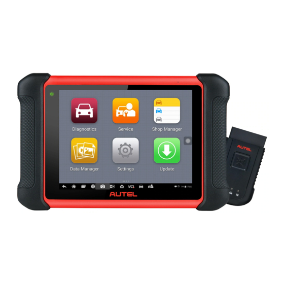
MaxiCOM – drags the inner ring to the top edge of the circle to enter the MaxiCOM Job Menu. Camera – drags the inner ring to the left edge of the circle to launch the camera Figure 3-1 Sample MaxiCOM MK906BT Job Menu Application Buttons Locator and Navigation Buttons Status Icons... -
Page 19: Application Buttons
NOTE: The screen is locked by default when you first turn on the Display Tablet. It is recommended to lock the screen to protect the information in the system and reduce the power consumption. Almost all operations on the Display Tablet are controlled through the touch screen. -
Page 20: Locator And Navigation Buttons
Remote Desk Operations on page 93. Launches Support platform which synchronizes Autel’s on-line service base station Support with the MaxiCOM tablet. See Support Operations on page 84. Allows you to store and play technical tutorial and training videos about the device usage or vehicle Academy diagnostic techniques. - Page 21 Table 3-2 Locator and Navigation Buttons Button Name Description Indicates the location of the screen. Swipe the Locator screen left or right to view the previous or next screen. Back Returns to the previous screen. Android Returns to Android System’s Home screen. Home Displays a list of applications that are currently Recent...
-
Page 22: System Status Icons
Tap the thumbnail image on the top right corner of the screen to view the stored image. Tap the Back or Home button to exit the camera application. Refer to Android documents for additional information. 3.1.3 System Status Icons As the Display Tablet is working with the Android operating system, you may refer to Android documents for more information. -
Page 23: Reboot System
In case of system crash, press and hold the Lock/Power button for 8 seconds to reboot the system. Installing Computer Software The MaxiCOM MK906BT Diagnostic Platform allows you to print the information needed for your convenience. To realize the printing function, you need to install the printer driver program. - Page 24 To perform printing through the computer Install the printer driver to the computer. Before printing make sure the Display Tablet is connected to the computer network, either via WiFi or LAN. See 9.1.3 Printing Setting on page 88 for more information. Run the MaxiSys Printer program on the computer to open up the printer interface.
-
Page 25: Chapter 4 Diagnostics Operations
Diagnostics Operations Chapter 4 By establishing a data link to the electronic control systems of the vehicle being serviced through the VCI device, the Diagnostics application allows you to retrieve diagnostic information, view live data parameters, and perform active tests. The Diagnostics application can access the electronic control module (ECM) for various vehicle control systems, such as engine, transmission, antilock brake system (ABS), airbag system (SRS) and more. -
Page 26: Vci Connection
To connect to an OBD II vehicle Insert the Vehicle Data Connector on the MaxiVCI V100 into the vehicle’s DLC, which is generally located under the vehicle dash. NOTE: The vehicle’s DLC is not always located under the dash; refer to the user manual of the test vehicle for additional connection information. - Page 27 communication is about 98.4 feet (about 30 m); this means you can perform vehicle diagnosis freely around the workshop with greater convenience. If you use more than one VCI device to connect to the test vehicles, you can perform vehicle diagnosis on various vehicles conveniently, by pairing the Display Tablet separately to each of the VCI devices connected to the different test vehicles, via wireless BT, without the need to repeat the plugging and unplugging procedure, which is unavoidable through traditional wired...
-
Page 28: No Communication Message
few seconds, and the Connection Mode LED on the MaxiVCI V100 illuminates solid green, indicating the connection between the devices is successful. The MaxiCOM diagnostic platform is now ready to perform vehicle diagnosis. NOTE: When both the communication methods are applied at the same time, the MaxiCOM system will use the USB communication as the default priority. -
Page 29: Getting Started
There is a loose connection. There is a blown vehicle fuse. There is a wiring fault on the vehicle or the adapter. There is a circuit fault in the adapter. Incorrect vehicle identification was entered. Getting Started Prior to first use of the Diagnostics application, make sure the VCI device has been synchronized with the Display Tablet to establish a communication link. - Page 30 Top toolbar Buttons The operations of the Toolbar buttons at the top of the screen are listed and described in the table below: Table 4-1 Top Toolbar Buttons Button Name Description Home Returns to the MaxiCOM Job Menu. Touching this button opens a dropdown list; tap VIN Scan Auto Detect for auto VIN detection;...
-
Page 31: Vehicle Identification
NOTE: The Update icon displayed on the upper right of the vehicle brand name indicates there is available update for the vehicle. Tap this icon to enter the Update application directly. Vehicle Identification The MaxiCOM diagnostic system supports four methods for Vehicle Identification. -
Page 32: Manual Vin Input
Figure 4-2 Sample Vehicle Diagnostics Screen In some cases when users have selected the vehicle brand instead of performing Auto VIN Scan in the first place, the system still provides an option for vehicle VIN scan. Figure 4-3 Sample Vehicle Selection Screen Select Automatic Selection and the system will proceed to acquire VIN information automatically or allow users to input the VIN manually. -
Page 33: Manual Vehicle Selection
MaxiCOM diagnostic system allows you to enter the vehicle VIN manually. To perform Manual VIN Input Tap the Diagnostics application button from the MaxiCOM Job Menu. The Vehicle Menu displays. Tap the VIN Scan button on the top toolbar. Select Manual Input. -
Page 34: Alternative Vehicle Identification
4.3.4 Alternative Vehicle Identification Occasionally, you may identify a test vehicle that the tester does not recognize; the database does not support, or has some unique characteristics that prevent it from communicating with the tester through the normal channels. In these instances, you are provided with the OBD direct entry, through which you can perform generic OBD II or EOBD tests. - Page 35 Diagnostics Toolbar The Diagnostics Toolbar contains a number of buttons that allow you to print or save the displayed data and make other controls. The table below provides a brief description for the operations of the Diagnostics Toolbar buttons: Table 4-2 Diagnostics Toolbar Buttons Button Name Description...
- Page 36 Button Name Description Records the communication data and information of the test vehicle. The saved data can be reported and sent to the technical center via the Data internet. Logging You can go to the Support application to follow up the processing progress, see 11.5 Data Logging page 88 for detailed information.
-
Page 37: Screen Messages
Tap the Send button to submit the report form via the internet, a confirmation message displays when sending is successful. Status Information Bar The Status Information Bar at the top of the Main Section displays the following items: Menu Title – indicates the menu subject of the Main Section VCI Icon –... -
Page 38: Making Selections
Warning Messages This type of messages informs you when completing the selected action may result in an irreversible change or loss of data. The typical example for this is the “Erase Codes” message. Error Messages Error messages inform you when a system or procedural error has occurred. Examples of possible errors include a disconnection or communication interruption due to certain reasons. - Page 39 Auto Scan – starts auto scanning for all the available systems on the vehicle Control Units – displays a selection menu of all available control units of the test vehicle Auto Scan The Auto Scan function performs a comprehensive scanning over all the systems on the vehicle’s ECU in order to locate fault systems and retrieve DTCs.
- Page 40 Column 2 – displays the scanned systems Column 3 – displays the diagnostic marks indicating different conditions of the test result: -!-: Indicates that the scanned system may not support the code reading function, or there is a communication error between the tester and the control system.
- Page 41 through a series of choices. You simply follow the menu driven procedure, and make proper selection each time; the program will guide you to the diagnostic function menu after a few choices you’ve made. Figure 4-7 Sample Function Menu Screen The Function Menu options vary slightly for different vehicles.
-
Page 42: Ecu Information
on the test vehicle, this selection may sometimes appear as Control Unit Adaptations, Special Functions, Variant Coding, Configuration, etc. NOTE: With the diagnostic toolbar on top of the screen throughout the whole diagnostic procedures, you are allowed to make various controls of the diagnostic information at any time, such as printing and saving the displayed data, getting help information, or performing data logging, etc. -
Page 43: Read Codes
Diagnostics Toolbar Buttons – see Table 4-2 Diagnostics Toolbar Buttons on page 28 for detailed descriptions of the operations for each button. Main Section – the left column displays the item names; the right column shows the specifications or descriptions. Functional Button –... -
Page 44: Erase Codes
Snowflake Icon – only displays when freeze frame data is available for viewing; Selecting this icon will display a data screen, which looks very similar to the Read Codes interface, therefore same operation method may be applied. Functional Button – only a Back (or sometimes an ESC) button is available;... - Page 45 Figure 4-10 Sample Live Data Screen Diagnostics Toolbar Buttons – taps the drop-down button at the top center of the screen and the toolbar buttons will display. See Table 4-2 Diagnostics Toolbar Buttons on page 28 for detailed descriptions of the operations for each button.
- Page 46 Tapping the drop-down button on the right side of the parameter name opens a submenu. There are 4 buttons to configure the data display mode, and one Help button on the right that you can tap for additional information. Each parameter item displays the selected mode independently. Analog Gauge Mode –...
- Page 47 and x8. Zoom-out Button – exits full screen display. To edit the waveform color and line thickness in a data graph Select 1 to 3 parameter items to display in Waveform Graph mode. Tap the Zoom-in Button on the right to display the data graph in full screen.
- Page 48 Manager, the preset flag will enable a popup to allow input of text to take notes. Clear Data – clears all previously retrieved parameter values at a cutting point whenever you choose. To Top – moves a selected data item to the top of the list. Graph Merge –...
- Page 49 can set the threshold values, an upper limit and a lower limit, for triggering the buzzer alarm. This function is only applied to the Waveform Graph display mode. MIN – tapping which opens a virtual keyboard, allowing you to enter the required lower limit value MAX –...
- Page 50 available: Manual – allows you to manually start and stop data recording DTC – auto triggers data recording when any DTC is detected DTC Check Mode – auto triggers data recording when certain pre-selected DTC types are detected Parameter – auto triggers data recording when any parameter value reaches the preset threshold Duration –...
-
Page 51: Active Test
4.6.5 Active Test The Active Test function is used to access vehicle-specific subsystem and component tests. Available tests vary depending on the manufacturer, year, and model, and only the available tests display in the menu. During an active test, the tester outputs commands to the ECU in order to drive the actuators. -
Page 52: Special Functions
4.6.6 Special Functions These functions perform various component adaptations, allowing you to recalibrate or configure certain components after making repairs or replacement. The main section of the Adaptation Operation screen displays a list of operational and vehicle status information, which mainly consists of four parts: The first part in the top line shows the description of the operation being performed, and the execution status is displayed on the right, such as Completed, Activated, etc. -
Page 53: Service
The third part displays the current conditions of the vehicle control module being learned for comparison to the preconditions suggested by the second part. If the current condition of the control module is out of the suggested limit value, you must adjust the vehicle condition to meet the requirement. -
Page 54: Function Descriptions
The most commonly performed service functions include: Oil Reset Service TPMS Programming Service EPB Service ABS/SRS Services SAS Calibration Service DPF Regeneration Service 4.7.1 Function Descriptions This section describes the main functions for vehicle service: Oil Reset Service This function allows you to perform reset for the Engine Oil Life system, which calculates an optimal oil life change interval depending on the vehicle driving... -
Page 55: Generic Obd Ii Operations
Steering Angle Sensor (SAS) Service This service function allows you to perform calibration for the Steering Angle Sensor, which permanently stores the current steering wheel position as the straight-ahead position in the steering angle sensor EEPROM. On successful completion of the calibration, the steering angle sensor fault memory is automatically cleared. - Page 56 submenu of various protocols. A communication protocol is a standardized way of data communication between an ECM and a diagnostic tool. Global OBD may use several different communication protocols. Select a specific protocol under the Protocol option. Wait for the OBD II Diagnostic Menu to appear.
-
Page 57: Function Descriptions
4.8.2 Function Descriptions This section describes the various functions of each diagnostic option: DTC & FFD When this function is selected, the screen displays a list of Stored Codes and Pending Codes. When the Freeze Frame data of certain DTCs are available for viewing, a snowflake button will display on the right side of the DTC item. - Page 58 test is reported. If the pending fault does not occur again within 40 to 80 warm-up cycles, the fault is automatically cleared from memory. Test results reported by this service do not necessarily indicate a faulty component or system. If test results indicate another failure after additional driving, then a DTC is set to indicate a faulty component or system, and the MIL is illuminated.
-
Page 59: Exiting Diagnostics
Live data can be displayed in various modes, see Live Data on page 38 for detailed information. O2 Sensor Monitor This option allows retrieval and viewing of O2 sensor monitor test results for the most recently performed tests from the vehicle’s on-board computer. The O2 Sensor Monitor test function is not supported by vehicles which communicate using a controller area network (CAN). - Page 60 NOTE: Damage to the vehicle electronic control module (ECM) may occur if communication is disrupted. Make sure all connections, such as USB cable and wireless connection, are properly connected at all times during testing. Exit all tests before disconnecting the test connection or powering down the tool.
-
Page 61: Chapter 5 Maxifix Operations
MaxiFix Operations Chapter 5 The MaxiFix application launches the on-line troubleshooter database, which not only provides you virtually all common diagnostic trouble code (DTC) database for most vehicles, but also serves as a forum allowing you to network with other MaxiCOM users, and gives you access to a vast database of repair and diagnostic tips along with proven filed fixes. - Page 62 The Main Screen – located at the center of the screen displaying content based on the vehicle attributes and keywords specified. The tabs on the main screen vary in accordance with the section selected on the Navigation Menu, allowing you to switch between functions. The Navigation Menu –...
-
Page 63: Terminology
5.1.1 Terminology MaxiFix Tip A MaxiFix Tip provides practical information of real fix of a specific vehicle repair issue with detailed descriptions. It is combined with proven fix and vehicle specific data, and filed into an all-in-one information source to provide you with quick and easy repair solutions. -
Page 64: Operations
OBDII Fault Codes description and reference – helps in diagnostic assessment by making clear the nature of an automotive problem so that beginner and advanced technicians can make effective repairs Real Fix Tips – provides repair tips from actual shop practices and are presented in an easy to understand Complaint, Cause, Correction format. -
Page 65: Home
to your activities in the Question section. Support – opens the FAQ page, or a message box for contacting Customer Service by email. 5.2.1 Home Home is the first option on the Navigation Menu at the bottom of the screen. Tapping it opens your MaxiFix home page. -
Page 66: My Maxifix
If not already done, click Select Vehicle on the Header to specify the vehicle you are asking about. Click Ask on the Navigation Menu at the bottom of the screen to open the Ask page. On the Ask page find Ask for Help, fill in the following sections to ask a question. - Page 67 Marked Posts – opens a list with links to Tips and discussions that you are actively participating in. My Profile – allows you to view your Autel account information including: your Autel ID, personal information, MaxiFix score, phone number and register time, and edit your portrait.
-
Page 68: My Messages
View Profile Information You can view your personal profile by clicking on your account ID or “My Profile” in My MaxiFix section or edit portrait where applicable, and visit other community members’ profile by clicking their portrait. Information included in your profile determines how you are presented to the community, and what type of information will be sent to you from the community. -
Page 69: Support
Close a Question When a repair question that you've posted to the community is resolved, you are encouraged to write down the case as a way to share a good solution. This will help the other MaxiFix members to find useful information for practical fix. To close a question, you need to select the question’s response message from the message list on “My Messages”... -
Page 70: Shop Manager Operations
Shop Manager Operations Chapter 6 The Shop Manager application helps you to manage the workshop information, customer information records, and keep test vehicle history records, which can be a great assist in dealing with daily workshop business and improves customer service. There are three main functions available: ... -
Page 71: Vehicle History
Button Name Description Touching this button opens the Vehicle History Vehicle screen which displays the correlated test vehicle History records. Done Completes editing and saves the file. Vehicle History This function stores records of test vehicle history, including vehicle information and the retrieved DTCs from previous diagnostic sessions, and displays all information in an easy-to-check table list, on which you can view summarized details and manually input other information about the test vehicle and diagnostic loggings, etc. -
Page 72: Historical Test Record
Select Vehicle History Tap the Diagnostics button at the bottom of the thumbnail of a vehicle record item. Or, Select a vehicle record item by tapping the thumbnail. A Historical Test record sheet displays, check the recorded information of the recorded test vehicle, and tap the Diagnostics button on the upper right corner. -
Page 73: Workshop Information
To edit the Historical Test record sheet Tap the Shop Manager application on the MaxiCOM Job Menu. Select Vehicle History. Select the specific vehicle history record thumbnail from the main section. The Historical Test record sheet displays. Tap the Edit button to start editing. Tap on each item to input the corresponding information or add attaching files or images. -
Page 74: Customer Manager
Figure 6-3 Sample Workshop Information Sheet To edit the Workshop Information sheet Tap the Shop Manager application on the MaxiCOM Job Menu. Select Workshop Information. Tap the Edit button on the top toolbar. Tap on each field to input the appropriate information. Tap Done to save the updated workshop information sheet, or tap Cancel to exit without saving. -
Page 75: History Notes
□ Tap the + photo frame beside the Name chart to add a photo. A sub menu displays, select Take Photo to take a new photo for the account, or select Choose Photo to choose from the existing files. Some customers may have more than one vehicle for service; you can always add new vehicle information to the account to be correlated. - Page 76 notes and photos, to keep multi-media work logs for the associated customer account, which can be very helpful when dealing with repeat customers. Keeping notes for each vehicle serviced for each customer will keep you always on track and well organized in business. ...
- Page 77 Table 6-2 Function Buttons in History Notes Button Name Description Back Returns to the previous screen. Delete Touching this button deletes the selected note. Quickly locates the required note by entering Search the note title. Touching this button to cancel edit or file Cancel search.
-
Page 78: Chapter 7 Data Manager Operations
Data Manager Operations Chapter 7 The Data Manager application is used to store, print, and review the saved files. Most operations are controlled through the toolbar. Selecting the Data Manager application opens the file system menu. Different file types are sorted separately under different options, there are six types of information files to be viewed or played back. - Page 79 Figure 7-2 Sample Image Database Screen Toolbar Buttons – used to edit, print and delete the image files. See Table 7-1 Toolbar Buttons in JPG Database on page 72 for detailed information. Main Section – displays the stored images. Table 7-1 Toolbar Buttons in JPG Database Button Name Description...
-
Page 80: Pdf Files
Select Image to access the JPG database. Select an image to display it in full screen. Tapping the screen once displays the editing toolbar. Tap the Info button to open a window displaying the image information. Tap the Edit button on the top right corner of the window. The editing screen displays. -
Page 81: Apps Manager
Figure 7-3 Sample Data Playback Screen Drop-down Toolbar – taps the button at the top center of the screen to open the Drop-down Toolbar Main Section – displays the recorded data frames Navigation Toolbar – allows you to manipulate data playback Use the Navigation Toolbar buttons to playback the record data from frame to frame. -
Page 82: Chapter 8 Settings Operations
Settings Operations Chapter 8 Selecting Settings application opens a setup interface, on which you can adjust default setting and view information about the MaxiCOM system. There are seven options available for the MaxiCOM system settings: Unit Language Printing Setting ... -
Page 83: Printing Setting
Internet. It is highly recommended to keep this function on all the time, so you won’t miss out any new update for MaxiCOM or event from Autel. Internet access is required for receiving on-line messages. ... -
Page 84: About
Tap the ON/OFF button to enable or disable the Notifications function. If the function is enabled the button turns blue, or if disabled the button turns gray. Tap the Home button on the top left corner to return to the MaxiCOM Job Menu. - Page 85 Tap the System settings option on the left column. Tap the App Switcher option on the left column. Mark the checkbox beside “Always show the App Switcher” on the right side of the screen, then the App Switcher icon shows. Short pressing the App Switcher icon opens a control panel: ...
-
Page 86: Chapter 9 Update Operations
Update Operations Chapter 9 The Update application allows you to download the latest released software. The updates can improve the MaxiCOM applications’ capabilities, typically by adding new tests, new models, or enhanced applications to the database. The Display Tablet automatically searches for available updates for all of the MaxiCOM software when it is connected to the internet. - Page 87 Right Side – displays an update progress bar indicating the completion status. Main Section Left Column – displays vehicle logos and update software version information. Middle Column – displays a brief introduction about the new changes to the ...
-
Page 88: Chapter 10 Vci Manager Operations
VCI Manager Operations Chapter 10 This application allows you to pair up the Display Tablet with the VCI device, check the communication status, and update the VCI software. Figure 10-1 Sample VCI Manager Screen Connection Mode – there are three connection modes available for selection. The connection state is displayed alongside. -
Page 89: Update
To pair the VCI device with the Display Tablet Power on the Display Tablet. Insert the 16-pin vehicle data connector of the MaxiVCI V100 to the vehicle data link connector (DLC). Tap the VCI Manager application on the MaxiCOM Job Menu of the Display Tablet. - Page 90 The current version and the latest version of the VCI software will be displayed after a few seconds, click Update Now to update the VCI software if available.
-
Page 91: Chapter 11 Support Operations
On the Sign In page, input your account ID and other information to log in, if you already have an account. If you are a new member to Autel and do not have an account yet, click the Create Autel ID button on the left side. -
Page 92: Support Screen Layout
User Info, Device Info, Update Info and Service Info. Personal Info The User Info and Device Info are both included under the Personal Info section. User Info – displays detailed information of your registered on-line Autel ... -
Page 93: User Complaint
Service Info The Service Info section displays a detailed record list of the device’s service history information. Every time the device has been sent back to Autel for repair, the device’s serial number and the detailed repair information, such as the fault type, changed components, or system reinstallation, etc., will be... - Page 94 Option Bar Period Filter – displays only the complaint records within the defined period on the list Status Filter – displays the corresponding complaint records according to the selected case status New Complaint Button – starts a new complaint case. ...
-
Page 95: Data Logging
Select the required processing time on the last section according to the urgency of the case. Tap Submit to send the completed form to Autel’s online service center, or tap Reset to refill it. The submitted complaints will be carefully read and handled by the service personnel, and the respond speed may depend on the processing time you’ve... -
Page 96: Communities
The Communities section launches and synchronizes with the Technical Forums on Autel’s official website www.autel.com, where you are allowed to discuss technical topics or share information with, as well as ask for technical advices or offer technical supports to all other members in Autel’s online support communities. - Page 97 Figure 11-4 Sample Communities Home Screen To start a discussion Tap Start a discussion on the Communities Home screen. A list of the major forums is displayed. Select a desired group according to the subject you are about to discuss.
- Page 98 Browse through all the posts by sliding the screen up and down. Tap Go to original post when reaching the end of the discussion to return to the first post. Tap Reply to reply a specific post, or tap Reply to original post to join and continue the whole discussion.
-
Page 99: Training Channels
11.8 FAQ Database The FAQ section provides you comprehensive and abundant references for all kinds of questions frequently asked and answered about the use of Autel’s online member account, and shopping and payment procedures. Account – displays questions and answers about the use of Autel’s ... -
Page 100: Chapter 12 Training Operations
The application also allows you to download or watch more associated videos online, by providing quick links to Autel’s online video database. Figure 12-1 Sample Training Application Screen Navigation Buttons –... -
Page 101: Chapter 13 Remote Desk Operations
You can use the application to receive ad-hoc remote support from Autel’s support center, colleagues, or friends, by allowing them to control your MaxiCOM tablet on their PC via the TeamViewer software. - Page 102 shown. Your partner must install the Remote Control software to his/her computer by downloading the TeamViewer full version program online (http://www.teamviewer.com), and then start the software on his/her computer at the same time, in order to provide support and take control of the Display Tablet remotely. Provide your ID to the partner, and wait for him/her to send you a remote control request.
-
Page 103: Chapter 14 Quick Link Operations
Quick Link Operations Chapter 14 The Quick Link application provides you with convenient access to Autel’s official website and many other well-known sites in automotive service, which offers you abundant information and resources, such as technical help, knowledge base, forums, training, and expertise consultations, etc. -
Page 104: Chapter 15 Oscilloscope Operations
Please download the latest user manual for Autel MaxiScope from www.autel.com. 15.1 Safety Information Follow these instructions to reduce the risk of injury from electric shock and prevent equipment damage. - Page 105 Safety Information on page 97. Product Maintenance The product contains no user-serviceable parts. Repair, servicing and calibration require specialized test equipment and must only be performed by Autel Tech Support or an approved service provider. DANGER: To prevent injury or death, do not use the product if it appears to be damaged in any way, and stop use immediately if you are concerned by any abnormal operations.
-
Page 106: Glossary
15.2 Glossary AC/DC Control Each channel can be set to either AC coupling or DC coupling. With DC coupling, the voltage displayed onscreen is equal to the true voltage of the signal with respect to ground. With AC coupling, any DC component of the signal is filtered out, leaving only the variations in the signal for the AC component. - Page 107 Time Base The time base controls the time interval across the scope display. Voltage Range The voltage range is the range between the maximum and minimum voltages that can be accurately captured by the oscilloscope. Sinusoidal Waveform This term describes the waveform characteristics typically found in circuits with large inductance and capacitance, and often referred to as an AC signal.
-
Page 108: Maxiscope Module
Figure 15-2 Sample Square Waveform Peak to peak voltage This term indicates the difference in voltage between the minimum and maximum voltages occurring in the waveform. 15.3 MaxiScope Module The MaxiScope Automotive Oscilloscope tool kit is optional and available for purchase along with the MaxiCOM package. - Page 109 Figure 15-3 Front, Rear, and Top View USB Port Connector Input Channel A/B/C/D LED Indicator Light – lights up when powered on, blinks when communicating, and shimmers when error occurs Warning Triangle – indicates potential safety hazard that exists on the indicated connections, and appropriate precautions should be taken.
- Page 110 Technical Specifications Main Features Description Vertical resolution 12 bits Channels Bandwidth 20MHz Accuracy Voltage: 1%; Time: 50ppm Sensitivity 10mV/div to 20V/div ±50mV to ±100V in 11 ranges Input Ranges (full scale) Input Impedance 1MΩ in parallel with 22pF Input Type Single-ended, BNC connector Input Coupling Software selectable AC/DC...
-
Page 111: Screen Layout And Operations
General Description USB 2.0 – cable supplied PC Interface Power Requirements Powered from USB port Compliance FCC (EMC), CE (EMC and LVD), RoHS Warranty 1 year NOTE*: Reduced to 20MS/s if channels A and B, or C and D, are enabled. 15.4 Screen Layout and Operations The Oscilloscope application works as a signal processing program that displays the shape of electrical signals onscreen with a live graph showing... -
Page 112: Top Toolbar
Top Toolbar – used for configurations of various settings and operations of the scope Functional Buttons on the top – used for configurations of channel activation, measurement scale and trigger settings Measurement Grid – displays measurements of voltage against time Functional Buttons at the bottom –... - Page 113 Button Name Description Tapping this button opens a submenu, on which displays 5 options allowing you to save, record and plays back the waveform data. Tap Save current page to take a screenshot image. Tap Record data to save the current waveform data.
- Page 114 Tap the desired option on the right column to enable the math channel in the channel list. The Math Channel displays on the MaxiScope screen. Probe A probe is any transducer, measuring device or other accessory that you connect to an input channel of your MaxiScope module. Reference Waveform A Reference Waveform is a copy of an existing signal waveform saved as a reference.
-
Page 115: Functional Buttons
alongside. Tap Yes and the selected reference waveform will appear on the scope screen. Figure 15-6 Recall Reference Waveform Window 15.4.2 Functional Buttons This group of buttons is used for configurations of channel activation, measurement scale and trigger settings, the operations of which are described below: Channel Control Buttons A/B/C/D –... -
Page 116: Measurement Grid
point. 15.4.3 Measurement Grid The 2 control features - Voltage per division and Time per division – enable the users to adjust the scope settings to suit the particular test measurement. Figure 15-7 Sample Measurement Grid Voltage per division – shown down the left side of the screen, referred to ... -
Page 117: Measurement Rulers
Adjust the voltage scale of the selected channel with the typical 2-finger zoom gestures. The 0 volts is hinted with a pointer reference line. Slide the pointer line up and down to move and view different areas of the scale. Tap once on the screen area outside of the Y-axis to finish the voltage scale adjustment. -
Page 118: Functional Buttons
Figure 15-8 Measurement Rulers Display 15.4.5 Functional Buttons This group of buttons includes trigger setting buttons allowing you to set trigger source and trigger mode, a Time base button for adjustment, and a Measurement button with options for various measurement types. Trigger On/Off –... -
Page 119: Troubleshooting
Auto Mode – configures the trigger to occur every time when the scope captures the signal waveforms by the preset trigger point. The scope continues to draw the waveforms even when the signal is not in the trigger point range. Main Time Base –... -
Page 120: Maxiscope Firmware Update
15.6 MaxiScope Firmware Update The operating software of the MaxiScope is continuously being developed, and the update package can be downloaded free from the MaxiScope product webpage on Autel’s website: http://www.autel.com. To update the MaxiScope firmware Install the CD provided with the MaxiScope tool kit into the CD-ROM of the computer. -
Page 121: Chapter 16 Digital Inspection Operations
Digital Inspection Operations Chapter 16 The Digital Inspection application configures the Display Tablet to operate as a digital video scope by simply connecting the tablet to a Digital Inspection Camera. This function allows you to examine difficult-to-reach areas normally hidden from sight, with the ability to record digital still images and videos, which offers you an economical solution to inspect machinery, facilities, and infrastructure in a safe and quick way. -
Page 122: Additional Accessories
16.1 Additional Accessories The Digital Inspection Camera and its fittings are the additional accessories. Both sizes (8.5 mm and 5.5 mm) of the imager head are optional and available for purchase along with the standard MaxiCOM tool kit. Digital Inspection Camera Figure 16-1 Digital Inspection Camera Removable Imager Head Cable –... - Page 123 Imager Head Accessories Figure 16-2 8.5mm Imager Head Accessories Magnet – picks up small metal objects, such as dropped rings or screws Hook – unclogs obstacles and picks up wires in the pipes or confined areas Mirror – helps to look around corners and see the unreachable areas Figure 16-3 5.5mm Imager Head Accessories Mirror –...
- Page 124 Slip the end of the accessory over the imager head and then fix the accessory. For 5.5mm Imager Head The two accessories, including the Magnet and Mirror (Figure 16-3), can be attached to the Imager Head with the same manner described below: Hold the accessory and the imager head.
-
Page 125: Technical Specifications
Screw the thread part of the accessory over the imager head to fix the accessory. 16.1.1 Technical Specifications Table 16-1 Technical Specifications Item Description Optimal 1" to 14" (2.54cm to 35.56cm) with 8.5mm diameter imager head Viewing Distance 3/8" to 12" (0.95cm to 30cm) with 5.5mm diameter imager head Image Capture JPG images (640x480) AVI videos (320 x 240) - Page 126 To take pictures using the Digital Inspection application Connect the Imager Head Cable to the USB port on the top side of the Display Tablet. If not already done, power up the Display Tablet. Tap the Digital Inspection application on the MaxiCOM Job Menu. The Digital Inspection application interface displays, showing a camera operating screen.
- Page 127 Tap the red circle again to stop recording. The recorded video is automatically saved to the system Gallery. Tap the thumbnail image on the top right corner to review the recorded video. Tap the Play button to play the video. 10.
-
Page 128: Chapter 17 Maintenance And Service
Maintenance and Service Chapter 17 To ensure that the MaxiCOM diagnostic tablet and the combined VCI unit perform at their optimum level, we advise that the product maintenance instructions covered in this section is read and followed. 17.1 Maintenance Instructions The following shows how to maintain your devices, together with precautions to take. -
Page 129: Troubleshooting Checklist
Your device may have not been connected to the charger properly. Check the connector. NOTE: If your problems persist, please contact Autel’s technical support personnel or your local selling agent. 17.3 About Battery Usage Your tablet is powered by a built-in Lithium-ion Polymer battery. This means that, unlike other forms of battery technology, you can recharge your battery while some charge remains without reducing your tablet’s autonomy due to... -
Page 130: Service Procedures
Do not use a damaged battery charger. Do not disassemble or open crush, bend or deform, puncture or shred. Do not modify or remanufacture, attempt to insert foreign objects into the battery, expose to fire, explosion or other hazard. ... - Page 131 Visit our website http://pro.autel.com or www.autel.com. Repair Service If it becomes necessary to return your device for repair, please download the repair service form from www.autel.com, and fill in the form. The following information must be included: Contact name ...
-
Page 132: Chapter 18 Compliance Information
Compliance Information Chapter 18 FCC Compliance FCC ID: WQ8MAXISYSMY906BT This equipment has been tested and found to comply with the limits for a Class B digital device, pursuant to Part 15 of the FCC Rules. These limits are designed to provide reasonable protection against harmful interference in a residential installation. - Page 133 level of the device while operating can be well below the maximum value. This is because the device is designed to operate at multiple power levels so as to use only the power required to reach the network. To avoid the possibility of exceeding the FCC radio frequency exposure limits, human proximity to antenna should be minimized.
-
Page 134: Chapter 19 Warranty
Chapter 19 12-Month Limited Warranty Autel Intelligent Technology Corp., Ltd. (the Company) warrants to the original retail purchaser of this MaxiCOM Diagnostic Device, that should this product or any part thereof during normal consumer usage and conditions, be proven defective in material...
Need help?
Do you have a question about the MaxiCOM MK906BT and is the answer not in the manual?
Questions and answers