Autel MaxiTPMS TS401 Manual
Hide thumbs
Also See for MaxiTPMS TS401:
- Manual (25 pages) ,
- User manual (25 pages) ,
- Update instructions (1 page)
Table of Contents
Advertisement
1.
SAFETY PRECAUTIONS AND WARNINGS ............................................ 1
2.
GENERAL INFORMATION ...................................................................... 2
2.1
2.2
2.3
2.4
3.
TOOL INFORMATION .............................................................................. 4
3.1
3.2
3.3
3.4
....................................................................................................... 6
3.5
3.6
3.7
4.
TPMS ACTIVATION ................................................................................ 18
4.1
V
4.2
4.3
4.4
5.
SOFTWARE UPDATE .............................................................................. 30
6.
WARRANTY AND SERVICE................................................................... 32
6.1
6.2
Table of Contents
................................................................................. 2
-
TPMS .................................................................................. 3
.................................................................................. 4
....................................................................................... 5
............................................................................................... 6
................................................................................ 7
.................................................................................................. 7
.............................................................................. 18
.......................................................................................... 26
....................................................................................... 27
............................................................................. 28
................................................................................................. 32
............................................................................. 2
.......................................................................... 2
........................................................................... 5
............................................................. 32
Advertisement
Table of Contents

Related Manuals for Autel MaxiTPMS TS401


Summary of Contents for Autel MaxiTPMS TS401
-
Page 1: Table Of Contents
Table of Contents SAFETY PRECAUTIONS AND WARNINGS ..........1 GENERAL INFORMATION ..............2 TPMS ................2 SYSTEM REVIEW TPMS L ................. 2 EGISLATION TPMS ................2 TELL TALE LIGHT TPMS .................. 3 ENEFITS OF TOOL INFORMATION ................4 .................. 4 ESCRIPTION .................. -
Page 2: Safety Precautions And Warnings
1. Safety Precautions and Warnings To prevent personal injury or damage to vehicles and/or the scan tool, read this instruction manual first and observe the following safety precautions at a minimum whenever working on a vehicle: Always perform diagnosis or service in a safe environment. Wear safety eye protection that meets ANSI standards. -
Page 3: General Information
2. General Information 2.1 TPMS system review A tire pressure monitoring system (TPMS) is an electronic system designed to monitor the air pressure inside the pneumatic tires on various types of vehicles. TPMS report real-time tire-pressure information to the driver of the vehicle, either via a gauge, a pictogram display, or a simple low-pressure warning light. -
Page 4: Benefits Of Tpms
When diagnosing TPMS systems, you should understand what the TPMS tell-tale light means. When turning the ignition OFF to ON, the TPMS tell-tale should come on, and then go off, which indicates the system is working fine. If the light stays on, there would be a pressure problem. If the light flashes, there would be a system problem, which can range from faulty sensors to sensors on the vehicle that haven’t been learned to that vehicle. -
Page 5: Tool Information
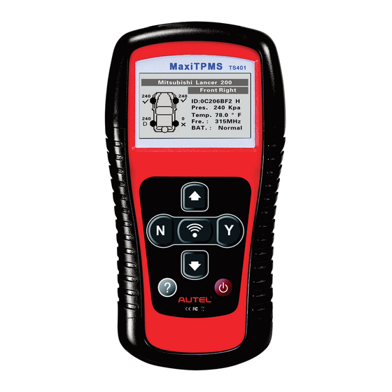
3. Tool Information 3.1 Tool Description Rubber BOOT – Protects the TPMS tool from drop, abrasion, and etc. LCD DISPLAY – Indicates test results. Backlit 128*64 pixel display with contrast adjustment. UP SCROLL BUTTON – Moves up through menu and submenu items in menu mode. -
Page 6: Specifications
N BUTTON – Cancels a selection (or action) from a menu or return to previous menu. DOWN SCROLL BUTTON – Moves down through menu and submenu items in menu mode. When more than one set of data are retrieved, use this button to move down to next screens for additional data. -
Page 7: Icons
USB Cable -- Allows easy update through PC via internet connection. Carry Case – A case to store the tool when not in use. Magnet -- Used to trigger magnetically activated sensors (early model TPMS sensors) Power Adapter – Charges the built-in battery. CD –... -
Page 8: Battery Charging
No solvents such as alcohol are allowed to clean the keypad or display. Use a mild nonabrasive detergent and a soft cotton cloth. Do not soak the keypad as the keypad is not waterproof. 3.6 Battery Charging The tool has a 3.7v built-in lithium-ion polymer rechargeable battery. There are two means of battery charging: To charge battery by power adapter. - Page 9 Auto Power-off: Sets the time to power off automatically. Contrast: Adjusts the contrast of the LCD display. Backlight Set: Turns on/off the backlight. 10) Tool Information: Views the important information of the tool. Settings of the unit will remain until change to the existing settings is made.
- Page 10 Use the UP/DOWN SCROLL button to select the desired language and press the Y button to save your selection and return to the previous screen. We provide three language options currently. Figure 3.3 ID Format From System Settings screen, use the UP/DOWN SCROLL button to select ID Format, and press the Y button.
- Page 11 Figure 3.5 Press the Y button to save your settings and return to previous menu, or press the N button to exit without change. Pressure Unit From System Settings screen, use the UP/DOWN SCROLL button to select Pressure Unit, and press the Y button. Figure 3.6 From Pressure Unit screen, use the UP/DOWN SCROLL button to select the desired unit: Kpa, Psi or Bar.
- Page 12 Figure 3.7 Temperature Unit From System Settings screen, use the UP/DOWN SCROLL button to select Temperature Unit, and press the Y button. Figure 3.8 From Temperature Unit screen, use the UP/DOWN SCROLL button to select the desired unit of temperature. (Figure 3.9) Press the Y button to save your settings and return to the previous menu, or press the N button to exit without change.
- Page 13 Beep Set This function allows you to turn on/off the build-in speaker for key pressing. From System Settings screen, use the UP/DOWN SCROLL button to select Beep Set, and press the Y button. Figure 3.10 From Beep Set menu, use the UP/DOWN SCROLL button to select Beep ON or Beep OFF to turn on/off the beep.
- Page 14 From System Settings screen, use the UP/DOWN SCROLL button to select Wheels to Test, and press the Y button. Figure 3.12 From Test Unit menu, use the UP/DOWN SCROLL button to select All Wheels or One Wheel mode for TPMS sensor testing. Figure 3.13 Press the Y button to save your selection or the N button to cancel and return to the previous menu.
- Page 15 Figure 3.14 Press the UP/DOWN SCROLL button to increase or decrease the time to auto power-off the tool, and then press the Y button to confirm your change or the N button to cancel and return to the previous menu. Figure 3.15 NOTE: Before the tool powers off automatically, it will save all the TPMS test data.
- Page 16 Figure 3.16 Press the UP/DOWN SCROLL button to adjust the screen display contrast, and then press the Y button to confirm your change or the N button to cancel and return to previous menu. Figure 3.17 Backlight Set The Backlight function allows you to adjust the screen backlighting. NOTE: Temperature or lighting may affect the brightness of the scan tool screen.
- Page 17 Figure 3.18 From Backlight Set menu, use the UP/DOWN SCROLL button to select Backlight ON or Backlight OFF to turn on/off the backlight. Figure 3.19 Press the Y button to save your selection or the N button to cancel and return to previous menu. Tool Information This function allows user to view some important information about the tool, such as serial number, software version and hardware...
- Page 18 View tool information on screen. Figure 3.20...
-
Page 19: Tpms Activation
4. TPMS Activation ® The MaxiTPMS TS401 is a hand held tool used to activate all magnetic, frequency, and tire deflation triggered sensors used on vehicle tire pressure monitoring systems to get information such as sensor ID, tire pressure, tire temperature, sensor battery, and frequency. - Page 20 Figure 4.1 The selected vehicle is remembered by the tool when a test is commenced. Select by Make Figure 4.2 Select by Model Figure 4.3 Select by Year...
- Page 21 Figure 4.4 Depending upon the reading mode (All Wheels or One Wheel), results are displayed in different manners. All Wheels Mode In this mode, the screen will display as below (Figure 4.5). The tool will do TPMS test in a sequence of FL (Left Front), FR (Right Front), RR (Right Rear), RL (Left Rear) and SPARE, if the vehicle has the option for the spare.
- Page 22 The tool will send LF signal to trigger the sensor. Depending on the sensor type, the tool will activate the sensor on the first or last step. Once the sensor is successfully activated and decoded, the tool will display as below with an audible beep. (Figure 4.6) Figure 4.6 After the sensor is activated, a test result icon, “√”...
- Page 23 Figure 4.7 In this mode, the tool will do TPMS test for each single wheel. Place the tool alongside the valve stem and point toward the sensor location and then press TEST button. Wait for test result before moving the tool. The tool will send LF signal to trigger the sensor.
- Page 24 √ Successful TPMS sensor is successfully activated and Sensor Read decoded. The tool displays the sensor information. Failed Sensor If the search period expires and no sensor Read activation or decode, it may be wrong sensor fitting or non-functioning sensor. The tool displays a message “No sensor detected.”.
- Page 25 the stem and then place the tool alongside the stem, and press TEST button. Figure 4.9 If the TPMS sensor requires tire deflation (of the order of 10PSI), then deflate the tire and place the tool alongside the stem while pressing TEST button. Figure 4.10 ...
- Page 26 Figure 4.11 Sensor activation can be aborted at any time by pressing the N button. When the activation is aborted, the tool will return to the previous menu. By pressing the Y button, you may review information of all sensors tested.
-
Page 27: Latest Scan
[Pos] – Indicates the wheel sensor position. [ID-H/D] – Shows sensor ID data. [KPa/Psi/Bar] – Indicates wheel pressure. [℃/℉] – Indicates wheel temperature. [BAT] – Indicates battery condition. [Mode] – Defines tire sensor working mode or status. [MDT] – Indicates sensor signal frequency. NOTE: Different ID format, pressure and temperature units will display at the title bar according to the device’s system setting, please refer to 2.7 Settings for detailed guidance. -
Page 28: Audit Report
A prompt comes up asking for your confirmation. Figure 4.15 Press the N button to playback the historical records. (Figure 4.16) Use the UP/DOWN SCROLL button to view additional information or press the N button to exit. Figure 4.16 Press the Y button to delete test records and enter test mode. For detailed procedure, please refer to section 4.1 Vehicle Selection. -
Page 29: Rke & Rf Monitor
the tool and computer. Once the explorer window is open, you may view a file by double-clicking on the file. If this explorer window does not automatically pop up, the user may browse for the newly connected device manually. The data presented is in a HTML form format that displays not only information regarding the TPMS, but also automatically updates with the date. - Page 30 Use the UP/DOWN SCROLL button to select RKE & RF Monitor from Main Menu (Figure 4.18), and press the Y button to confirm. Figure 4.18 Hold the key fob very close to the tool and press the function buttons on key fob to test. If the button works and the key fob is sending a signal, the tool will beep and the screen will show as below.
-
Page 31: Software Update
5. Software Update The tool allows user to update software. It works on computers running Windows systems (XP/2000/Vista/Windows7). To update software, you will need the followings: TS401 CD with update tool PC or laptop with USB ports ... - Page 32 the Update Mode forcedly. Then follow the update procedure to refresh the program. Run the Maxi-link II Kit in your computer. (Figure 5.2) Figure 5.2 Click Select File button to locate the latest update file you have recently downloaded. Click Update to start updating. Once the update is complete, the tool is updated and ready to go.
-
Page 33: Warranty And Service
6. Warranty and Service 6.1 Limited One Year Warranty Autel warrants to its customers that this product will be free from all defects in materials and workmanship for a period of one (1) year from the date of the original purchase, subject to the following terms and...
Need help?
Do you have a question about the MaxiTPMS TS401 and is the answer not in the manual?
Questions and answers